


- Joined
- Sep 23, 2018
- Messages
- 97
- Points
- 253

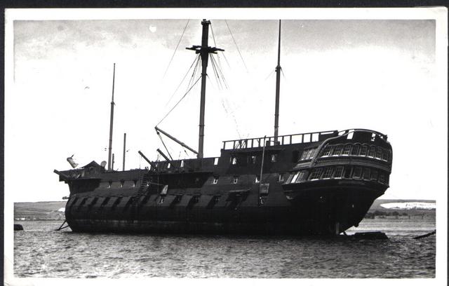
Many many moons ago I dreamed of building a large scale model of the old Implacable, formerly the Duguay-Trouin which was captured from the French two weeks after Trafalagar. Renamed Implacable she taken over by the Royal Navy and soldiered on for a century and a half until she was eventually scuttled in 1949!
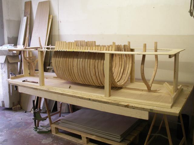
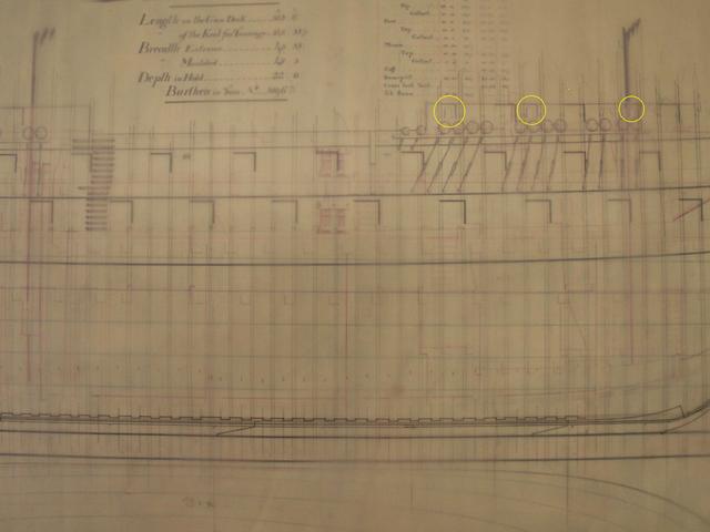
I got the plans from the NMM and started studying the ship. I then started to draw my own plans which included the hull frames. To figure out the width and the location of the frames I used the timberheads alongside the forecastle deck as guides, taking it for granted that they were actually (as the name says) the top pieces of timbers i.e. frames. At that time I shared my work on the other forum where someone pointed out that I was probably on the right track as all the frames lined up neatly between the gunports. I never realised this myself before it was pointed out to me and indeed, all frames fitted perfectly between the gunports. There was no need to notch any frame pieces to make the gunports fit. I was quite thrilled. I then also joined up in a French forum and everyone there told me I got it all wrong! The frames were erected completely disregarding the position of the gunports as these were to be chiseled out later. Quite disillusioned my Implable project slowly but surely died a natural death. This is what she looks like today:
First Thing I do when I come home from work nowadays is to check out @Uwek fantastic "Today in Naval History" thread. And there today was a frame plan of a Temeraire-class 74 gun ship from 1798, two years senior to the Duguay-Trouin.
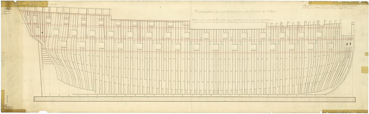
And what does this plan tell us? The frames all line up neatly between the gunports. No need to notch the frames to make the gunports fit later. I probably got it right after all. The plans I drew back then were drawn by hand, I tried to find them this evening but to no avail, I might have disposed of them at a thoughtless moment in the past. However, today in CAD-programme-age it be might be fairly easy to redraw the plans and re-animate my Implacable. But until then I have a Dutch-Twodecker to complete.
And here we have a splendid picture of the Implacable taken in the late 1930s.
Many thanks Uwe for showing us the plan!
Peter
I got the plans from the NMM and started studying the ship. I then started to draw my own plans which included the hull frames. To figure out the width and the location of the frames I used the timberheads alongside the forecastle deck as guides, taking it for granted that they were actually (as the name says) the top pieces of timbers i.e. frames. At that time I shared my work on the other forum where someone pointed out that I was probably on the right track as all the frames lined up neatly between the gunports. I never realised this myself before it was pointed out to me and indeed, all frames fitted perfectly between the gunports. There was no need to notch any frame pieces to make the gunports fit. I was quite thrilled. I then also joined up in a French forum and everyone there told me I got it all wrong! The frames were erected completely disregarding the position of the gunports as these were to be chiseled out later. Quite disillusioned my Implable project slowly but surely died a natural death. This is what she looks like today:
First Thing I do when I come home from work nowadays is to check out @Uwek fantastic "Today in Naval History" thread. And there today was a frame plan of a Temeraire-class 74 gun ship from 1798, two years senior to the Duguay-Trouin.
And what does this plan tell us? The frames all line up neatly between the gunports. No need to notch the frames to make the gunports fit later. I probably got it right after all. The plans I drew back then were drawn by hand, I tried to find them this evening but to no avail, I might have disposed of them at a thoughtless moment in the past. However, today in CAD-programme-age it be might be fairly easy to redraw the plans and re-animate my Implacable. But until then I have a Dutch-Twodecker to complete.
And here we have a splendid picture of the Implacable taken in the late 1930s.
Many thanks Uwe for showing us the plan!
Peter


 . But thanks for the useful information.