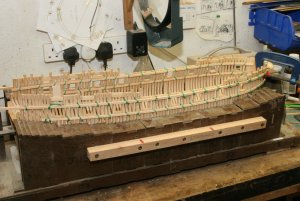
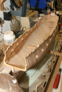
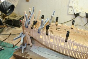
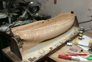
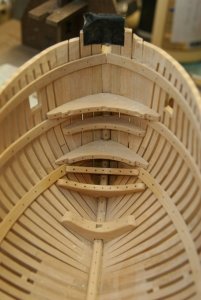
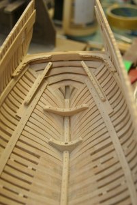
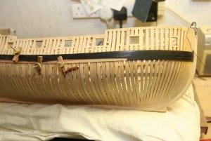
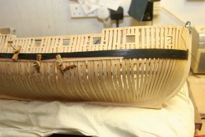
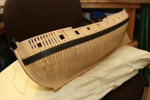
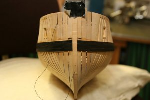
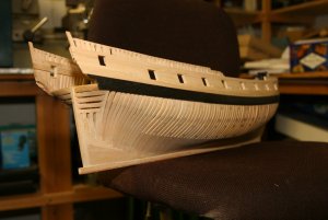
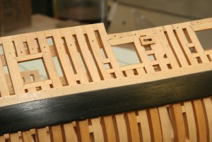
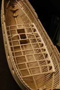
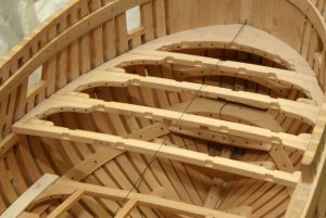
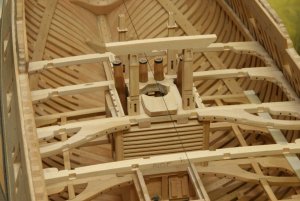
As promised, the write-up I put together on the way I approach trennels fastenings.
Treenails
Right; as promised; herewith my thoughts on treenails. Please note these are my own opinions, and should not be read as a hard and fast ‘do it this way’. There isn’t a ‘right way’ as such, and there are many ways of reaching the same result.
First; What are treenails? Basically, they are wooden pins used to fasten two timbers securely together, rather than using bolts or nails.
The shipwright would auger a hole through the timbers, and then drive in the round wooden treenail using a mallet. The treenail would be very slightly larger than the hole, so a really tight fit was obtained, and if water was taken up by the treenail, it would expand slightly, and make the fastening even tighter.
The Chatham dockyard of the period had two men on the books whose sole job was to make the treenails – boring or what!
British practice was to use mainly treenails to fasten planking (hull and deck) with hull planking ends often being fastened using bolts. French practice was to use a mixture of treenails, bolts and nails. I don’t know American practice, but would imagine it was likely to follow British.
Second; On a model, should you bother?
Entirely up to you. Some contemporary models (i.e. actually built in the 1700/1800’s) show the treenails, some don’t.
My own view is that models of 1/48 or larger will benefit from their inclusion, but anything smaller will be perfectly fine without them. It’s all to do with individual perception. Additionally, at 1/48 scale the treenails securing the decks and hull planking would be about 0.018” (18 thou), which is readily achievable, but at 1/96 (say), the treenails would be only 0.009” (9 thou), which I certainly wouldn’t like to attempt.
I only go down to 0.020" or 0.022” because I find it difficult to produce treenails smaller than this using a drawplate, as the wood tends to break below this point, and in addition Franklin, in ‘Navy Board Ship models 1650 – 1750’ states “Strangely enough, scale sized treenails of 1/32” or less always appear to be too small and insignificant on models, and actually look better if a little oversized”
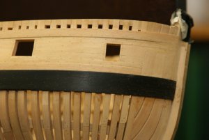
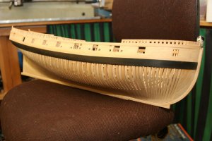
One other thing to think about is the spacing of frames and deck beams; full-size ships have multiple frames quite close together, while most of our models are built on widely spaced bulkheads. I have seen a lot of models where treenails have been employed, but only at bulkhead positions. It looks wrong, and it is quite easy to incorporate additional rows of treenails between the bulkheads, particularly if the hull is double planked
Third; Representation
To my mind, if you’re going to show the treenails, I would prefer to see actual treenails being used. It’s not essential, and treenails can be represented by ‘impressing’, using a large size hypodermic needle filed to a ring-shaped cutter, or by drilling holes and filling with a proprietary wood filler. Franklin, in ‘Navy Board Ship models 1650 – 1750’, notes that impressed treenails are seen on a number of contemporary models. Having said that, I have found that both the above methods are unsatisfactory, as impressing tends to dent the timber below the surface and cause a ‘dimple’, and filling gets messy and suffers from a lack of definition when sanded down.
Fourth; Materials
Most of my models are built using boxwood for the hull, and I prefer to use boxwood treenails. When put in, a boxwood treenail shows an end grain, which takes up a sealer or varnish rather more than the planking, and consequently appears rather darker. This contrast should be subtle, and indeed at more than three feet distant, should virtually disappear.
For this reason, I don’t favour bamboo, as I find the end grain is too prominent and open, and shows rather darker than I would want.
Decks are rather more awkward, as they tend to be of very much lighter coloured timber. On a full-size ship, they would be fastened using treenails made of the same material as the planking itself. My current model of Kingfisher employs Holly as deck planking, and I found it virtually impossible to produce treenails using a drawplate as the timber is relatively soft and breaks. I did try a different technique (Bernard Frolich’s technique) but found the finished result after sanding and scraping the deck was too good, as I could barely see the treenails at six inches!
I again took refuge in Franklin’s ‘Navy Board Ship models 1650 – 1750’ who notes that there is a present-day tendency for modellers to use rather more contrasting timbers than in the past, so I opted for boxwood treenails.
Be aware that commercial kits will often use softer material than boxwood, and the ‘definition’ of the treenails will decrease with the softness of the timber.
Always make up a test panel off the ship before committing yourself to a technique you might later regret using!
Fifth; Techniques
Much of this section has already appeared elsewhere in the forum, but it seems appropriate to include it again at this point, to preserve the continuity of the post:
When I started making treenails, I bought a Vanda-Lay treenail maker, and found it to be quite effective, but liable to break the timber using the smaller 0.025" cutter. This happened quite frequently, at which point I would have to dismantle the thing and poke around with a thin probe in order to get the bits out. There was a further problem in that 0.025" at 1/48 scale equates to about 1.2" full-size, which is a bit large for treenails for planking and decks, which should be about 0.75" (say 0.018" at model size) - It shows! Treenails fixing heavy timbers can however be larger – up to 1.25” (say 0.030”).
I then bought a Jim Byrnes drawplate, which really transformed the game. I use 1.0mm x 1.0mm (about 0.040" square) boxwood stringing which I bought from the Original Marquetry Company in Bristol, UK. This comes in metre long lengths (40") and the grain runs true. It's used by musical instrument makers for the banding on the faces of stringed instruments. I cut a pointed end on a strip, and then pull through the drawplate using a pair of flat-jawed jewellers pliers. I found I can draw down four lengths of stringing to 0.020” in about half an hour - that's sufficient material for about 500 to 600 treenails, allowing for wastage!
The original marquetry site can be found on
www.originalmarquetry.co.uk/ , but I'm sure there must be similar outfits over in the states. Incidentally, the same company can also provide black pressure-dyed boxwood stringing, so you can produce all the black treenails for the wales or representations of bolted fastenings!
Points to consider when using a drawplate:
1. Use a proper timber drawplate, such as Jim Byrnes’ – a jewellers drawplate is designed to reduce silver or gold wire to a smaller diameter, but does it by compression, rather than cutting.
2. The wood must be straight grained - if it's at all cross-grained it will break.
3. Mount the drawplate in a solid vice - you can't hand hold.
4. Start in a hole on the drawplate that will just accept the timber.
5. Use every hole in taking the timber down to size - don't be tempted to miss one or two out!
6. Use flat jaw pliers to pull the timber - serrated jaws will bruise the end of the timber and make it break.
7. Pull the timber through the hole steadily and at right angles to the plate.
8. Finally - and I do apologise if this sounds like teaching Grandma to suck eggs - make sure the drawplate is the right way round. The timber should be entered from the side with the hole sizes stamped in.
Actual procedures as follows:
Standard treenailing using hard woods: Make the treenail stock as above, then use a scalpel to make alternate angled and straight cuts along the timber at about 0.150” intervals to give you loads of treenails with a pointed end. Treenails are a bit like socks – you always find them getting lost, to turn up months later where you least expected them! So make plenty.
Mark out the positions of the treenails (Use any of the standard reference works to determine the spacing rules – or tell me if you’re flummoxed, and I’ll add an Addendum), and use a sharp point to make a starter hole. Drill the holes using a drill the same size as your treenails, or a thou or two larger (experiment) Pick up the treenail with forceps, dip in Welbond, and push into the hole until almost flush. When dry, cut off level with the deck using a scalpel, then sand and scrape to a good finish.
Frolich’s Method for softer woods: Used when you can’t pull treenails stock using a drawplate. Take a flat strip of timber, sand down to 0.020”, then cut a strip about 0.150” from the end, across the grain. Take this small strip and cut it along the grain, with the scalpel at a slight angle to make a wedge of material. Take the next cut at the opposite angle, and so on. This will produce individual wedge shaped treenails, which when dipped in glue and inserted in the drilled hole, will slightly deform to a round section and fill the hole. In this instance, experiment with the size of the drilled hole to enable the wedge to fill it.
Sixth; Common errors
Use of oversize treenails – if in doubt, make them small, or leave them out.
Poor marking out – lines of treenails should be straight or it looks wrong.
Using a jewellers drawplate.
Not using a test piece – It’s too late if you start on the hull and don’t like it!
When I posted this article on another forum, I had a response from a member who was having problems, so wrote a bit more about the techniques - might also be of use.
As I started to read your post I immediately thought 'I bet he's got the drawplate the wrong way round!'
Subsequent posts bear that out.
You should be readily able to pull the stringing through the drawplate in one pass and move to the next hole without having to pull it backwards and forwards several times. Possible causes of breakage are: timber slightly cross-grained; not pulling reasonably square to the drawplate; having the drawplate the wrong way round.
Getting the timber to enter the drawplate is initially fiddly, but once you've learned the trick then practice makes it perfect and easy. Mount the drawplate in the vice with the numbers away from you. Put a point on the timber (a single diagonal slash suffices) and introduce it to the hole by leaning over the vice. Grasp the timber immediately behind the head with the flat-jaw pliers held sideways, and hold everything in place by bracing your fingers against the drawplate before gently pushing the point through - The action is more like pulling the timber towards the hole - You should be aiming to have the pliers only about 1/8" away from the drawplate as you start pushing, and keep moving the pliers back to grab more timber as it enters the hole. I can readily pull the boxwood down to 0.018" using this technique - I get a few breakages, but not many these days.
When you grasp the protruding end on the timber, then you will get bruising and splitting of the timber, but I generally find it will keep it's shape for 2 or 3 holes in the plate - just resharpen and carry on - I pull my timbers in 40" lengths, and generally lose about 2" to 3" on the full length due to re-sharpening.
I have a Vanda-Lay cutter, but stopped using it a long time ago, as I genuinely find it much faster and easier to use the drawplate. In addition, the smallest treenail you can produce is 0.024", while most of the treenails I need are 0.018" or 0.020". It doesn't sound much, but it is very noticeable on the model.
Having said that, I can see that the Vanda-Lay would be handy on larger scale boats where you wanted to use Bamboo, as the shorter lengths of cane that you can split off the Bamboo will mean many more passes through a drawplate to produce the same number of treenails.
Keep persevering - you will get there!
That’s about it – Hope it helps!
Ted
