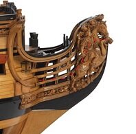
HMS Royal William 1719 1:55 by OlegM

Joined
Feb 11, 2019
Messages
383
Points
373

Location
Montreal
Hi everyone, seems that my new project is slowly moving step by step. Don't know if I ever manage to finish it, since there's a lot of stuff to work through, but... this was my dream ship for a long time and I spent a lot of days to prepare for it.
English is not my native language so I don't feel to be able to write big essays explaining all my research and why I did like this where I took these dimensions why shape like this and so on and so on, but I will do my best to describe my path at least in several words.

SOOO....
I base myself on the contemporary drawing of the ship that I bought at NMM (I actually bought two RW drawings j1787 and j1789 and also a drawing for deck plans of Victory 1737). I also use 4 contemporary models of RW, three of wich are located in NMM, the forth one is in USNA.

Of the three models in NMM, the one with the rigging is fundamentally different from the rest of William's models, even in its description it is written that this was either some kind of preliminary version rejected by the King, or something else. Therefore, I will not take this model into account when building at all, it does not make sense. Unless I will examine the rigging, if the quality of the photo allows, which is, of course, terrible. But in general for the masting and rigging I have the model in Annapolis, and Victory 1737 as a spare one.


I selected the scale according to the length of the ship that I want to get (about 1.5 meters). This scale is close to the imperial scale of 7/32" (ie 1 '= 7/32" or 1: 54.857), but for the convenience of recalculation, of course I chose 1:55.

1/48 would have come out about 1.75m somewhere, I decided that for now it is too much for me. Wouldn't be able to take it upstairs from the basement.

For the dimensions I use exclusively Goodwin's book and Establishment 1719.

Basic ship info:

Vessel dimensions:

Gundeck length 175'4 "or 971.665mm (1/55 onwards)
Keel length (theoretical) 142'7 "or 790.171mm
Breadth, extreme 50'3.5 "or 278.707mm
Depth in hold 20'1 "or 111.298mm
Burthen, tons 1918.

Armament:
28x 32p.
28x 18p.
28x 9p.
16x 6p.
 
Last edited:
Having drawings in hand, I started with 3d model.

I'll just say, perhaps, the obvious - about the purpose of my 3D model. I did not have the task of building the most accurate 3D model, taking into account all real structural elements. I do not build an admiralty model, and I do not create a 3D model as a separate, complete, fully developed project. The task of this 3D model is to prepare a set of parts for the CNC mill/laser in order to build a conventional model according to the philosophy of wooden kits, as well as be able to prepare a variety of templates, fixtures and take measurements. Therefore, I build a 3D model with an accuracy that I consider sufficient for the goal, as well as with the degree of elaboration that seems to me sufficient. The frames will be similar to kit frames, only much more thoughtful and exactly what I think it should be, well, or such as I personally like. I do it for myself. I came up with some kind of my own design, something really of my own, something like, probably, no one builds. I just understood what my goals were, what I wanted, and developed a design based on these goals.

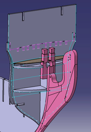
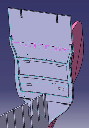
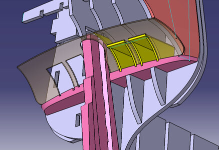
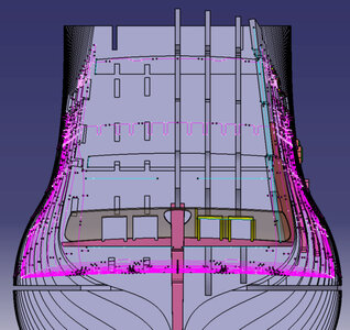
Also, I have no plans to build internal cabins, so the entire stern structure will be essentially fake. No internal elaboration and maximum simplifications that do not affect the appearance. Among others, I have two tasks: 1) to simplify as much as possible the task of marking and installing gunports, planksheer and decks, as well as whales, 2) to create templates, fixtures, and so on, neede for assembling of aft galleries etc. And also to assemble such a structure that will not deform anywhere, which will fit perfectly, will give perfect symmetry and correct contours.

I'm modeling in CATIA. I already have fun with her for 40 hours a week, so I think there is no need to learn another program, I think I will somehow figure it out in a familiar environment. For the CNC milling I also use CAM module of Catia and for the laser, I use Engraver Master a program that came with it. I prepare drawings also in Catia.
 
Here is the laser that I use:

The one that is called "20W" - it's actually a 7W diode and I equipped it with air compressor to supply air onto the focusing (cutting) point.

My CNC mill is this one:
It's a 4-axis 600x400 mm 800W spindle with ball screws and water cooling
 
Last edited:
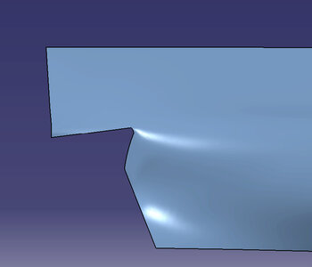
I will start posting with preliminary 3d modeling that was necessary to build the skeleton of the hull.
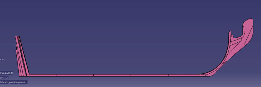
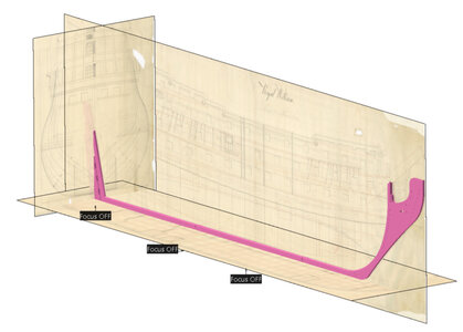
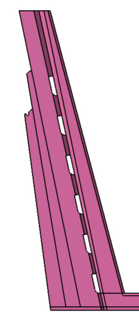
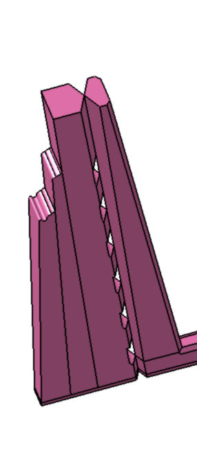
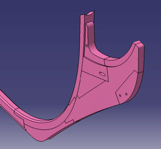
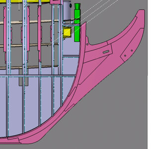
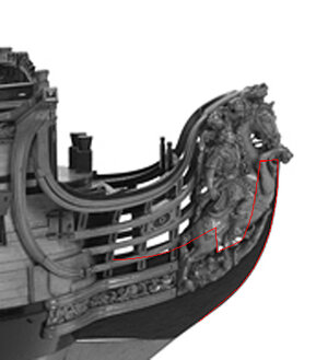
First the keel assembly. Boxing is simplified, as I said, this is not an admiralty model. But the correct keel thickness diminishing is reproduced - towards the stem, towards the stern. Also both stem and stern increase in thickness upward. The knee of the head thickness is decreasing towards the front.

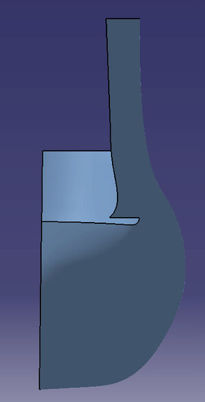
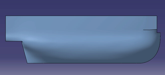
1-1.jpg1-1-1.jpg1-5.jpg1-6.jpg
 
Last edited:
It looks like your have your computer and milling skills to rune the machines and turn out your components. How close tolerance do you expect to have in reduction of filing and sanding? I am a no CNC /CAD hobbyist with basic cutting/sanding/drilling minitools requiring filing and sanding to mate the parts that I have to produce or eliminate the laser char. Old school but newer techniques definitely can produce some amazing results. Enjoy your build as you appear to have the plan well in place. Rich (PT-2)
 
Awesome project ! Greetings from a another Catia-Guy.
How you get the drawings in the CATIA ? I tried to do this various times but i dont trust the scale.
Sometimes it seems to me that Catia stretch the Image but maybe i choose the wrong way to import the image.
 
Great Project - this will be very interesting to follow

BTW: Did you see the 3D design of the HMS Royal George 1756 figurehead by @igorcap ?
Yes, most probably I will be outsourcing the 3d models of all the decorations. I'm more a tech guy rather than a sculptor or an artist, so for me it would be tough to model people, horses and the rest. When time comes, I will be looking for someone
 
Awesome project ! Greetings from a another Catia-Guy.
How you get the drawings in the CATIA ? I tried to do this various times but i dont trust the scale.
Sometimes it seems to me that Catia stretch the Image but maybe i choose the wrong way to import the image.

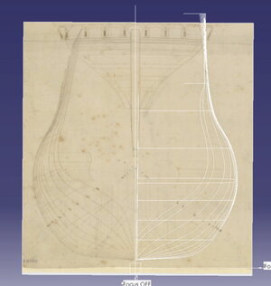
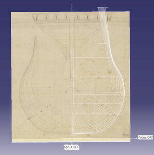
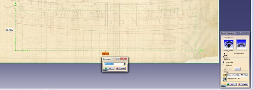
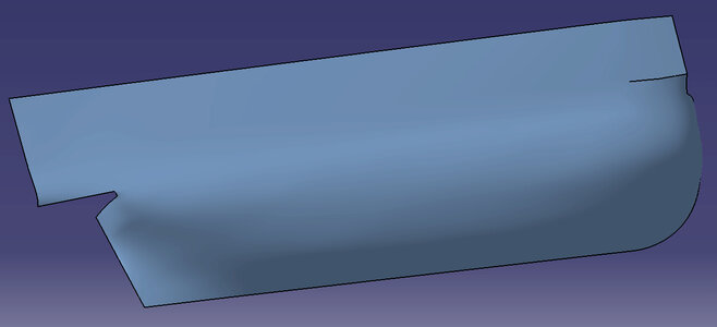
I use Sketch Tracer module. There you create an axis system and orient the picture in regards to it. There's a box, which you can move, rotate and scale, the axes have values which you can choose. For example, for this project on my drawing there was no scale chart. So I scaled the drawing ysing basic dimension "gundeck length". I positioned the box, so that it's X side is exactly gundeck length and then put value in mm in the box for this axis. The problem with Catia is that it doesn't allow independent scaling of the drawing in two axis. Once you scaled one axis, the second is automatic. So if the drawing/picture is distorted, it should be corrected first in PhotoShop for example.2.jpg
 
It looks like your have your computer and milling skills to rune the machines and turn out your components. How close tolerance do you expect to have in reduction of filing and sanding? I am a no CNC /CAD hobbyist with basic cutting/sanding/drilling minitools requiring filing and sanding to mate the parts that I have to produce or eliminate the laser char. Old school but newer techniques definitely can produce some amazing results. Enjoy your build as you appear to have the plan well in place. Rich (PT-2)
Me honestly I'm also learning everything on the run, this is first time for me working wth CNC and laser. So I gain experience and see what happens. For now I used laser only for plywood and inner structure. So no char was necessary to remove, so no dimensions reduction. There's a reduction of dimensions due to laser beam cutting thickness, I would say in my case every edge is lacking about 0.1mm of material, but I think this depends on the material thickness too. With the plywood the much bigger problem is actually the plywood thickness which can be like +/-0.3 easily.
As for the CNC parts for now I didn't include any additional material for sanding. I prefer to have a longer program to achieve a finer surface (by more passes and smaller mill). For now I milled just the keel pieces. Seems ok
 
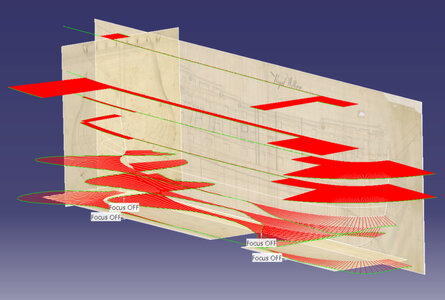
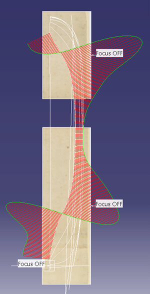
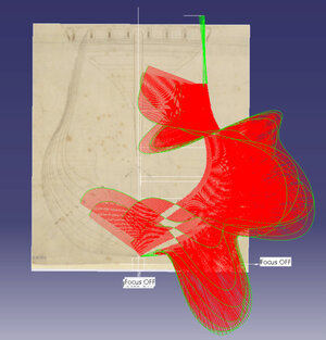
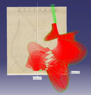
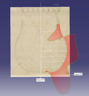
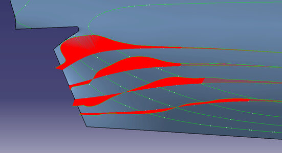
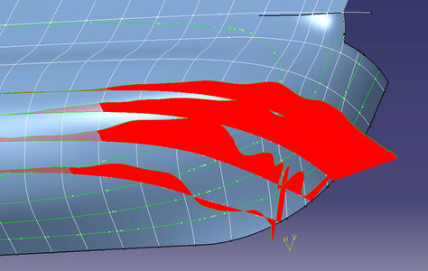
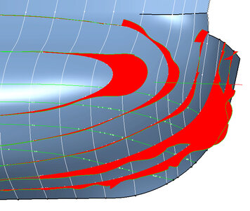
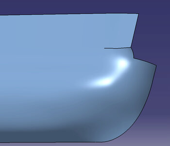
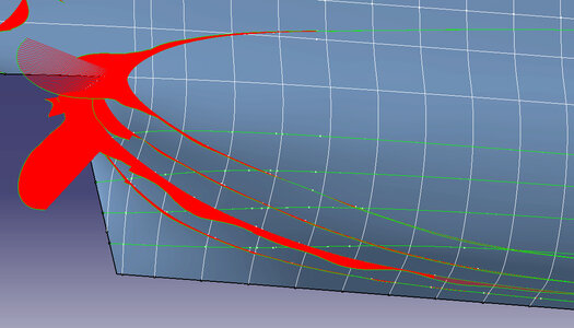
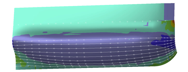
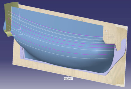
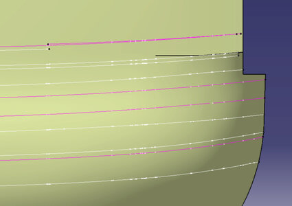
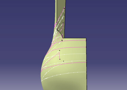
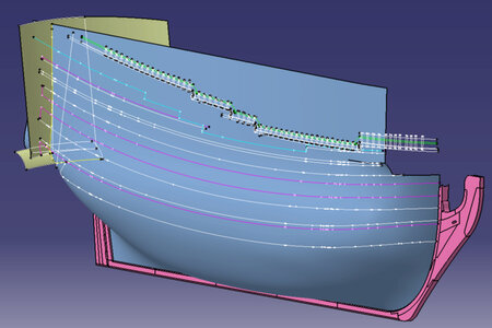
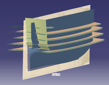
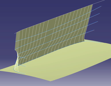
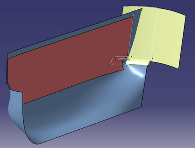
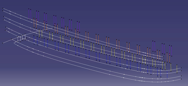
The next set of photos shows the process of theoretical geometry built-up of whales, rails, and planksheers. There are two sketches for the thickness of the external planking. 21-1 shows the values calculated from books and Establishment. 21-2 shows the thickness that I finally choose for the model (I substracted 0.4-0.8mm along all the planking to make it thinner keeping the same thickness differences between different areas. Also some of the areas are double-layered to ease my work). 21-3 and 21-4 is the main wale, which I decided to make top-and-butt fashion.


20.jpg20-1.jpg20-2.jpg21-1.jpg21-2.jpg21-3.jpg21-4.jpg22.jpg
 
Last edited:
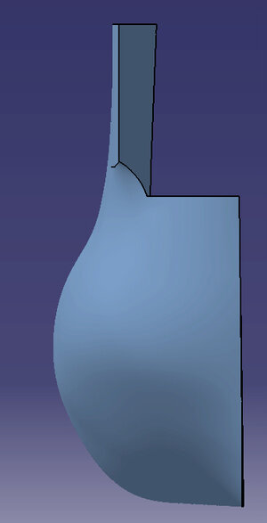
Next, I built the deck's geometry and frames the inner surface. Deck geometry is based on the two-layer concept. The first layer is 1mm plywood false deck and the second layer 1mm planking. The top surface is as per the drawing, but the lower one consequently no. For the inner surface I built it from the gundeck upwards, I don't need anything below the gundeck.
The last 2 photos are the geometry for the gunports

23.jpg24.jpg24-1.jpg25.jpg25-4.jpg
 
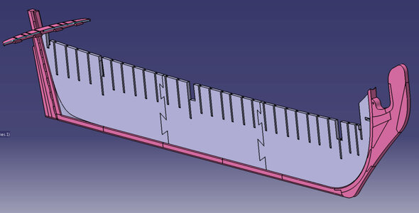
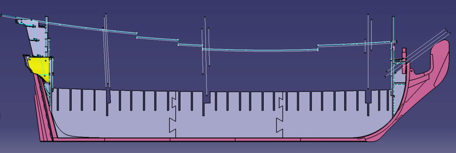
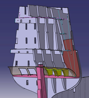
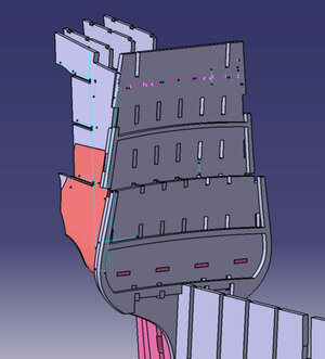
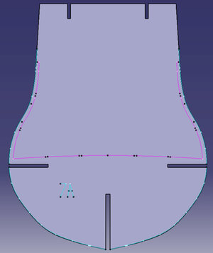
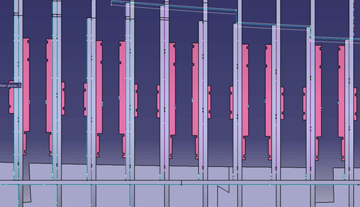
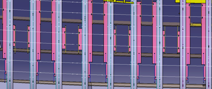
Based on the theoretical geometry I designed the hull inner structure. It is assembled partially on laser cut plywood (grey), partially on the CNC-milled pear blocks and parts (pink). The keel frame is double-layered from 5 parts with spaced joints. The plywood bulkheds are located strictly in between the gunports, 30 pieces total. The pink lines are the contours that are cut through by the laser (for example, bulkhead inner contours), blue lines - those engraved by the laser.

26-1.jpg26-2.jpg27-1.jpg27-2.jpg28-1.jpg28-2.jpg28-3.jpg28-4.jpg
 
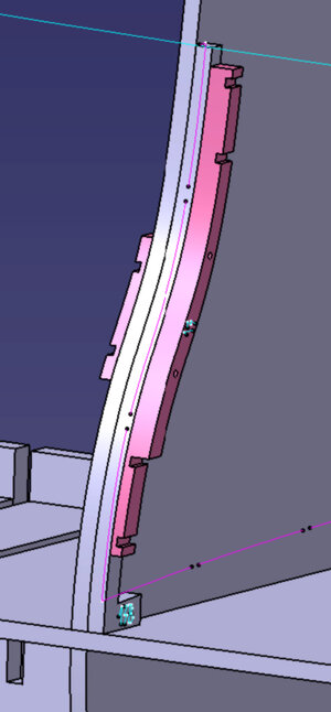
All the bulkheads consist of 4 layers. One layer is a solid piece of plywood, where the bulkhead inner contour is cut through by the laser, but some bridges are left to keep the inner material in place while I need it. Second layer is also plywood, just the bulkheads sides from gundeck level all to the top (explanation for 2 layers of plywood is simple: my laser would not be able to cut the thickness if it was one layer). Other two layers are milled pear inserts that form the gunports vertical sills for three main decks.

30.jpg32-2.jpg32-2-1.jpg32-3.jpg
 
Back
Top