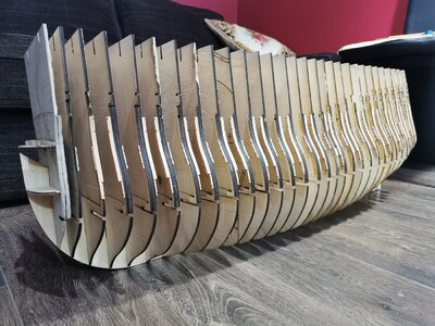
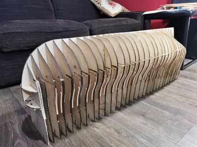
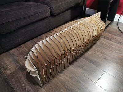
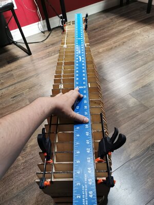
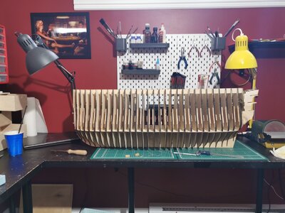
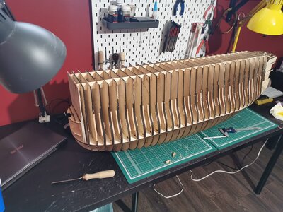
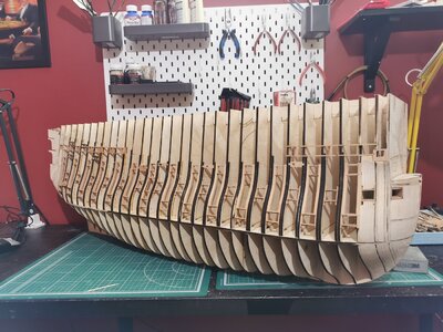
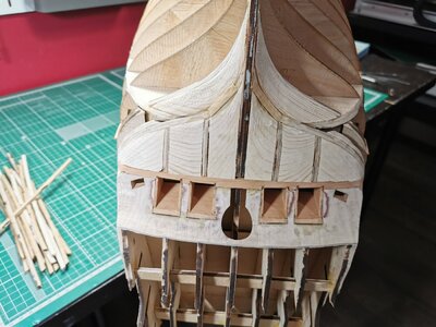
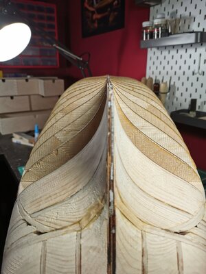
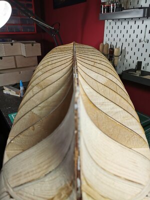
Yes, that’s the issue with diode lasers, so many passes at a very slow speed but better than no laser.it's 4 mm and I have to do 4-5 passes. Each bulkhead took me about 10-15 min per pass.
I'm replacing the diode now, the lens and the air compressor, so hope for better performance
-

Win a Free Custom Engraved Brass Coin!!!
As a way to introduce our brass coins to the community, we will raffle off a free coin during the month of August. Follow link ABOVE for instructions for entering.
-

PRE-ORDER SHIPS IN SCALE TODAY!
The beloved Ships in Scale Magazine is back and charting a new course for 2026!
Discover new skills, new techniques, and new inspirations in every issue.
NOTE THAT OUR FIRST ISSUE WILL BE JAN/FEB 2026
You are using an out of date browser. It may not display this or other websites correctly.
You should upgrade or use an alternative browser.
You should upgrade or use an alternative browser.
Yes, when I say "milled" I mean that I used my CNC-mill machine to make them. Unfortunately I didn't do much photos, I post here all that I haveVery good idea / solution and performance..... are these parts also cnc-cut?
Do you have a photo how you do this? One by one or in a group ?
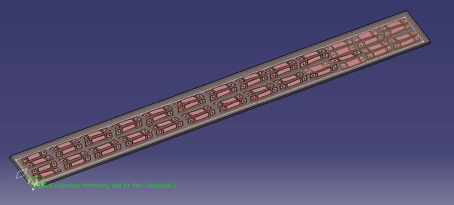
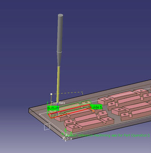
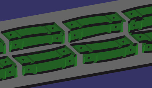
Mill the parts one by one is not efficient. I use plates, usually my supplier has them in 500x50mm for pear and 400x45 for hornbeam.
So before ordering the materials I create something like a work order for myself. I define the amount of work, design all the parts that will be needed, then choose the thicknesses of the plates trying to keep them at minimum numbers, locate the parts inside these plates and write one program for each plate. Then order the exact quantity of plates at exact thicknesses that I need.
Like this:
It's true, a CO2 laser is at least $2000 while mine is only $500 and even if I need to replace the diode for $100 every half a year it's still cheaper... If I had $2000-3000 I would buy a CO2, but...Yes, that’s the issue with diode lasers, so many passes at a very slow speed but better than no laser.
I cannot reply in one sentence.What drill are you using on the cnc, and feed rates and depth of passes?
The feed rate and depth of passes depend on material, bit diameter, bit length and spindle speed. In the internet some tables can be found with recommendations on these parameters or not-to-exceed parameters, but this helps only to some extent. Then it all depends on the mill table rigidity, performance of the step-motors and their maximum speed, the willing of you to go easy or not on the spindle bearings, the willing of you on how many bits you want to break.... That's a whole universe.
I have about 20 of different bits with different diameters and lengths, and that's only for flat end mill bits, I'm not touching other types of bits yet. So with every bit I choose, the parameters will be different. The best thing is to find a table in the Internet with general recommendations. Mine is in Russian so it will be useless to you.
The longer is the bit, the smaller is feedrate and depth per pass
the lower is the feedrate, the lower is the spindle speed or vice versa
the distance between passes depend on the bit diameter and is usually no more than 50-70%
Also depth of cut and distance between passes may be reduced if you desire a smoother surface...
And so on
This up to current technology takes model building far above the old school hands on cutting, filing, sanding of my level. Amazing what younger generations have evolved and find natural and possibly intuitive. I just worked in the transition from drafting boards to the earliest forms of CAD drafting, pre-3-D. Rich (PT-2)I cannot reply in one sentence.
The feed rate and depth of passes depend on material, bit diameter, bit length and spindle speed. In the internet some tables can be found with recommendations on these parameters or not-to-exceed parameters, but this helps only to some extent. Then it all depends on the mill table rigidity, performance of the step-motors and their maximum speed, the willing of you to go easy or not on the spindle bearings, the willing of you on how many bits you want to break.... That's a whole universe.
I have about 20 of different bits with different diameters and lengths, and that's only for flat end mill bits, I'm not touching other types of bits yet. So with every bit I choose, the parameters will be different. The best thing is to find a table in the Internet with general recommendations. Mine is in Russian so it will be useless to you.
The longer is the bit, the smaller is feedrate and depth per pass
the lower is the feedrate, the lower is the spindle speed or vice versa
the distance between passes depend on the bit diameter and is usually no more than 50-70%
Also depth of cut and distance between passes may be reduced if you desire a smoother surface...
And so on
Yeah, still these machines are quite expensive...This up to current technology takes model building far above the old school hands on cutting, filing, sanding of my level. Amazing what younger generations have evolved and find natural and possibly intuitive. I just worked in the transition from drafting boards to the earliest forms of CAD drafting, pre-3-D. Rich (PT-2)
Well me, I'm an engineer in aerospace, so 3-d is my job, I just had to learn CAM to start this project.
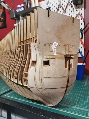
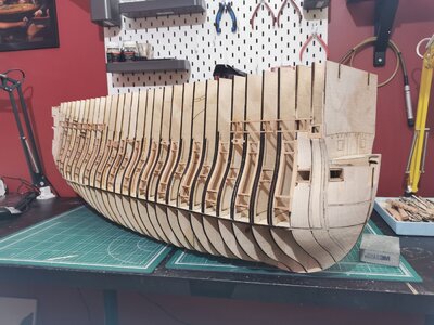
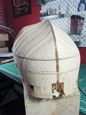
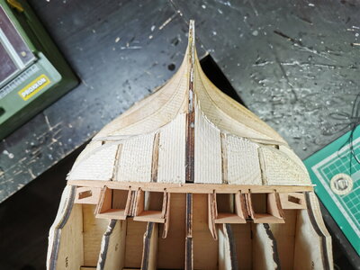
Installation of the gunport sills. For three main decks these are just strips of wood cut in segments and installed in the slots that were milled in the vrtical pear inserts.
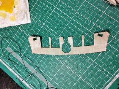
For quarterdeck first the horizontal strips with slots are milled, installed in the bulkheads, and then vertical sills installed in the slots
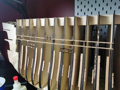
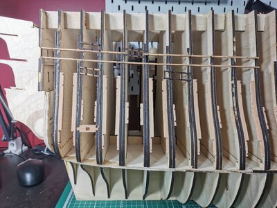
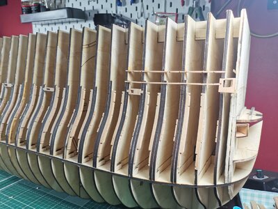
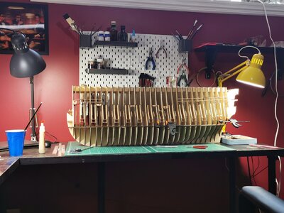
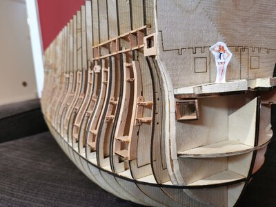
For quarterdeck first the horizontal strips with slots are milled, installed in the bulkheads, and then vertical sills installed in the slots


Great work preparation and very interesting execution - Really very interesting to see your work.
BTW: I like your small figurehead lady standing on the bow of your model - is she correct in scale?
I guess she is able to motivate you and helping in the shipyard
BTW: I like your small figurehead lady standing on the bow of your model - is she correct in scale?
I guess she is able to motivate you and helping in the shipyard
Ladies on the ship - is the bad sign...I guess she is able to motivate you and helping in the shipyard
I was trying to make it to scale, but she came up a little too tall ) she is around 1.9-1.95m with heelsGreat work preparation and very interesting execution - Really very interesting to see your work.
BTW: I like your small figurehead lady standing on the bow of your model - is she correct in scale?
I guess she is able to motivate you and helping in the shipyard
Hi Oleg,
Fantastic work, love it.
Do I see a new kit on the horizon. You have all the files now to do it.
Fantastic work, love it.
Do I see a new kit on the horizon. You have all the files now to do it.
Honestly this thought is circulating in my mind from time to time )) doubt that this is realistic thoughHi Oleg,
Fantastic work, love it.
Do I see a new kit on the horizon. You have all the files now to do it.
you never know...well...until you will try.Honestly this thought is circulating in my mind from time to time )) doubt that this is realistic though
I don't think I can create a full set of quality drawings. Everything I need is in 3d, but it's pretty simple, no full ship rendering. In any case let's at least build this oneyou never know...well...until you will try.


