-

Win a Free Custom Engraved Brass Coin!!!
As a way to introduce our brass coins to the community, we will raffle off a free coin during the month of August. Follow link ABOVE for instructions for entering.
-

PRE-ORDER SHIPS IN SCALE TODAY!
The beloved Ships in Scale Magazine is back and charting a new course for 2026!
Discover new skills, new techniques, and new inspirations in every issue.
NOTE THAT OUR FIRST ISSUE WILL BE JAN/FEB 2026
You are using an out of date browser. It may not display this or other websites correctly.
You should upgrade or use an alternative browser.
You should upgrade or use an alternative browser.
HMS St Albans (1687) model in scale 1:48
- Joined
- Sep 7, 2020
- Messages
- 27
- Points
- 78

Thank you Stephan and welcome aboardGreat build, I will follow with great interest.

- Joined
- Sep 7, 2020
- Messages
- 27
- Points
- 78

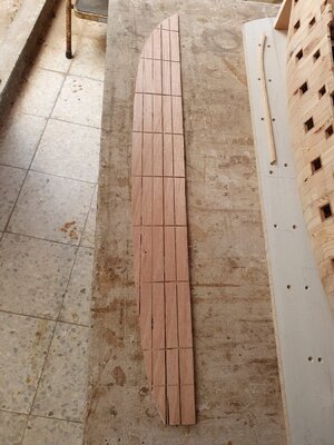
I am not a supporter of reproducing details where this is not necessary, so I made the base of the gun deck out of plywood and made the transverse bend by hand grinding. Plywood layers help maintain precision along the entire length
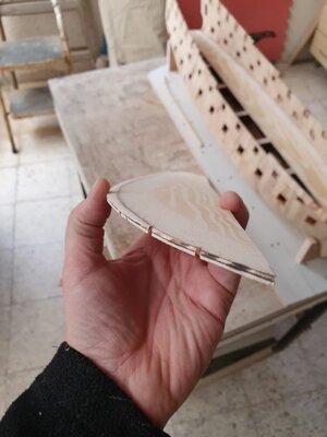
To prevent deformation of the plywood, I sawed grooves of different depths - in accordance with the thickness of the material in a particular place.
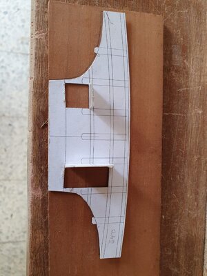
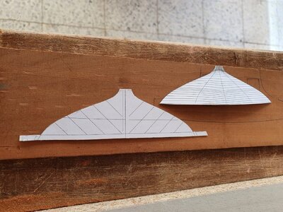
Finally, it's time to start working on the ends of the ship's hull.
Rhino still helps a lot in work - with it it is easy to make templates and even reamers where necessary.
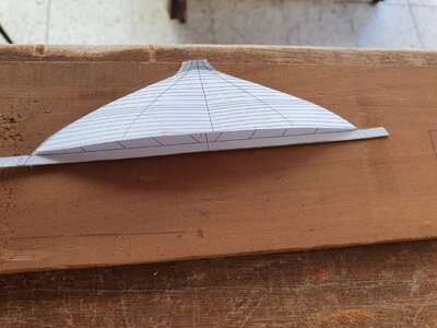
the front wall of the forecastle is in the place,
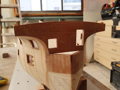
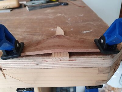
but the transom board will have to dry out after 20 minutes in boiling water
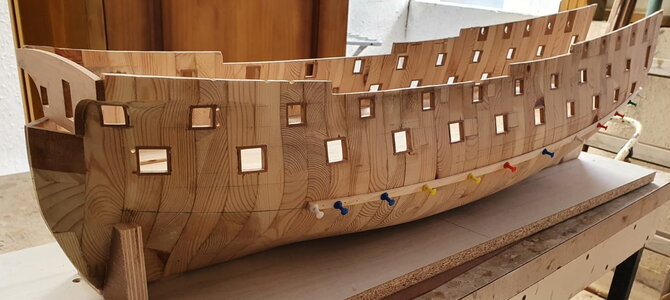
In the meantime, I can prepare for the underbody planking. I'm starting to install a temporary wales

To prevent deformation of the plywood, I sawed grooves of different depths - in accordance with the thickness of the material in a particular place.

Finally, it's time to start working on the ends of the ship's hull.
Rhino still helps a lot in work - with it it is easy to make templates and even reamers where necessary.


the front wall of the forecastle is in the place,

but the transom board will have to dry out after 20 minutes in boiling water

In the meantime, I can prepare for the underbody planking. I'm starting to install a temporary wales

What an astonishing build and a great inspiration to recycle my old childroom's writimgtable into a hull model! Thanks a lot for the interesting impressions from your model yard.
Good decision to do the wales first as baroque ships frames were hold by wales and afterwards planked so the run of the planks is parallel to the wles and only in distance starting to get their own run.
Looking foreward to your building's progresses. I didn't got separated plans with THE SHIPMASTERS SECRETS - where are your plans from?
Last edited:
I think this is a fabulous way to build a model. It cuts down on the weight with the hollow hull. 
- Joined
- Sep 7, 2020
- Messages
- 27
- Points
- 78

What an astonishing build and a great inspiration to recycle my old childroom's writimgtable into a hull model! Thanks a lot for the interesting impressions from your model yard.
Good decision to do the wales first as baroque ships frames were hold by wales and afterwards planked so the run of the planks is parallel to the wles and only in distance starting to get their own run.
Looking foreward to your building's progresses. I didn't got separated plans with THE SHIPMASTERS SECRETS - where are your plans from?
Hi Chris,
Thank you for you amazing reaction on my first model project from wood.
As for the drawings I even had to carry out a small investigation to remember exactly where, because once I downloaded from the network everything related to shipbuilding of the 17th century.
the measurement drawing of the Robert Spencer St. Albans model I initially downloaded from the forum http://forum.modelsworld.ru about 10 years ago.
Actually, this drawing became the basis of the drawing of the book - in the book it is only drawn more accurately.
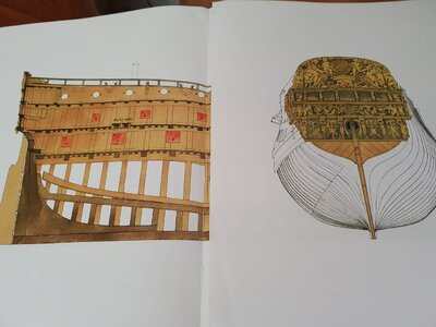
The same drawing was posted by Alexander Foxtrott at https://shipsofscale.com/sosforums/threads/saint-albans-1687-in-navy-board-style-1-48-scale.3593/
Regards
Oleg
- Joined
- Sep 7, 2020
- Messages
- 27
- Points
- 78

I think this is a fabulous way to build a model. It cuts down on the weight with the hollow hull.
Bryian - probably all this looks impressive in work, but now I would choose the method of Igor Kapinos (Andrey Kudin also built his model on it), when the shell of the hull is glued with pine planks 2 mm thick.
This method has at least 2 important advantages.
1) Initial longitudinal strength.
2) There is NO HUGE amount of dust.
- Joined
- Sep 7, 2020
- Messages
- 27
- Points
- 78

And a little update:
When working with the temporary wales, the main idea was to shape the top row of bottom planks and the middle wale board. Both have the same thickness and removing the temporary wale, it will be possible to process planks with sandpaper before installing thicker parts.
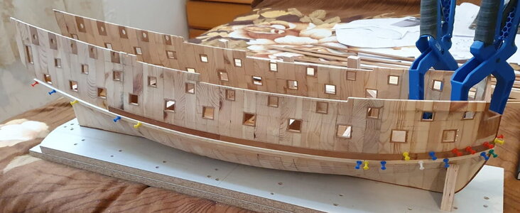
Of course, I made the first mistake, forgetting to coat the temporary wale with oil, so that drips of glue would not stick it to the main parts
The next difficult place was the crossing of wale board with the last cannon port. I wanted to paint the joint in advance: the red color seems to me too saturated in comparison with the red ocher used in the 17th century, but this can be corrected later. (And an unexpected discovery - masking tape does not work on a not sanded wood surface )
)
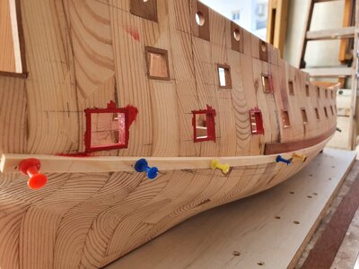
in addition, due to the fact that the part was inserted under pressure, it was difficult to find the correct direction of the cut. It turned out on the fourth attempt.
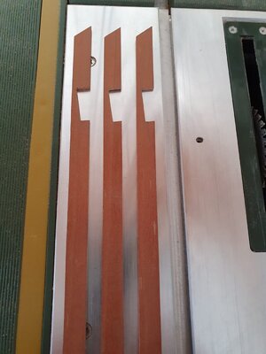
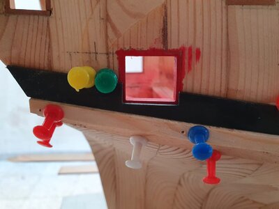
The clamp is another reminder of the weak longitudinal strength of the case - it was necessary to re-glue the seam between the frames, which appeared due to the efforts required to install the locking buttons.
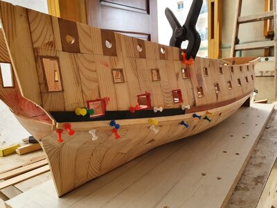
Subtotal after temporary wale deleting

When working with the temporary wales, the main idea was to shape the top row of bottom planks and the middle wale board. Both have the same thickness and removing the temporary wale, it will be possible to process planks with sandpaper before installing thicker parts.

Of course, I made the first mistake, forgetting to coat the temporary wale with oil, so that drips of glue would not stick it to the main parts
The next difficult place was the crossing of wale board with the last cannon port. I wanted to paint the joint in advance: the red color seems to me too saturated in comparison with the red ocher used in the 17th century, but this can be corrected later. (And an unexpected discovery - masking tape does not work on a not sanded wood surface

in addition, due to the fact that the part was inserted under pressure, it was difficult to find the correct direction of the cut. It turned out on the fourth attempt.


The clamp is another reminder of the weak longitudinal strength of the case - it was necessary to re-glue the seam between the frames, which appeared due to the efforts required to install the locking buttons.

Subtotal after temporary wale deleting

- Joined
- Sep 7, 2020
- Messages
- 27
- Points
- 78

By the way - it's good to check again what interested me many years ago - you can find something that escaped attention then: I found photographs of Kelvin Moneypenny from Trinity House and I want to post them here:
(from http://forum.modelsworld.ru/topic4775start90.html)
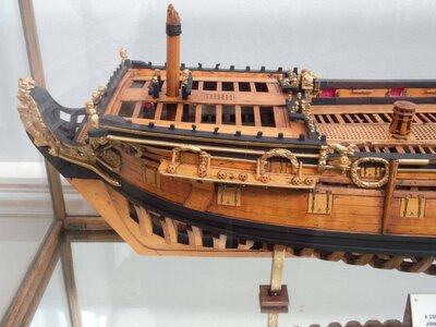
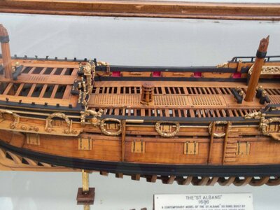
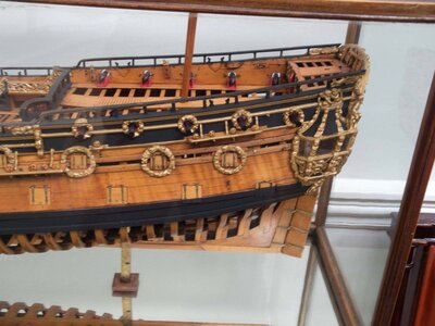
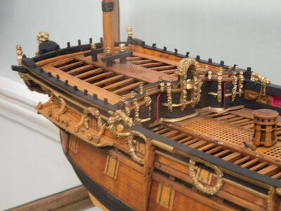
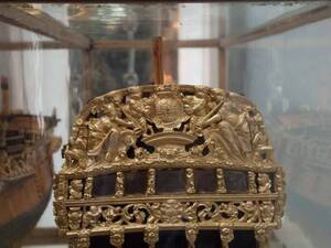
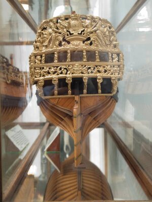
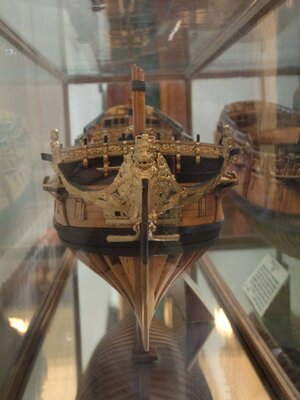
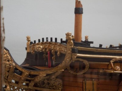
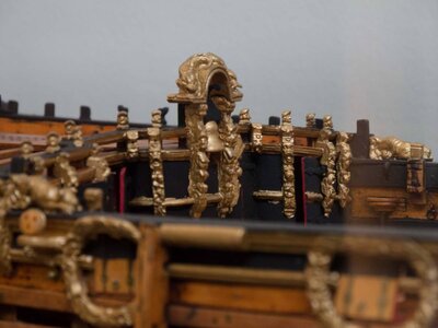
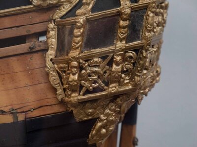
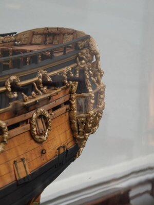
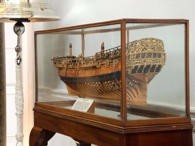
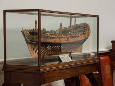
(from http://forum.modelsworld.ru/topic4775start90.html)


Well done Oleg.And a little update:
When working with the temporary wales, the main idea was to shape the top row of bottom planks and the middle wale board. Both have the same thickness and removing the temporary wale, it will be possible to process planks with sandpaper before installing thicker parts.
View attachment 224836
Of course, I made the first mistake, forgetting to coat the temporary wale with oil, so that drips of glue would not stick it to the main parts
The next difficult place was the crossing of wale board with the last cannon port. I wanted to paint the joint in advance: the red color seems to me too saturated in comparison with the red ocher used in the 17th century, but this can be corrected later. (And an unexpected discovery - masking tape does not work on a not sanded wood surface)
View attachment 224842
in addition, due to the fact that the part was inserted under pressure, it was difficult to find the correct direction of the cut. It turned out on the fourth attempt.
View attachment 224843
View attachment 224844
The clamp is another reminder of the weak longitudinal strength of the case - it was necessary to re-glue the seam between the frames, which appeared due to the efforts required to install the locking buttons.
View attachment 224845
Subtotal after temporary wale deleting
View attachment 224850
I like your work very much. Congrats.
I want to ask something about rhino.
I use rhino for obtaining the frames for POB models. I use often "section" and contour" commands
But I've never tried to form the hull from frame curves.
Which command or commands are used to make a surface from frame curves.
Thanks in advance.
Bilal
- Joined
- Sep 7, 2020
- Messages
- 27
- Points
- 78

Thank you Bilal !Well done Oleg.
I like your work very much. Congrats.
I want to ask something about rhino.
I use rhino for obtaining the frames for POB models. I use often "section" and contour" commands
But I've never tried to form the hull from frame curves.
Which command or commands are used to make a surface from frame curves.
Thanks in advance.
Bilal
About hull surface building let me make small tutorial (it is better to be overly detailed than to miss some important nuances)
To build a surface with double curvature, we need a closed network of curves that Rhino can use to build the surface.
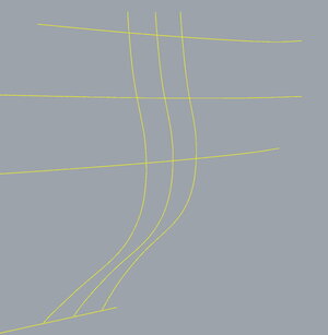
For example, I took 3 frames, a keel line and a couple more curves that outline the side. The more curves you can use, the more accurate the surface will be.
In the case of strong curvature, it is preferable to make several surfaces instead of one (you can see such dividing on my hull placed behind)
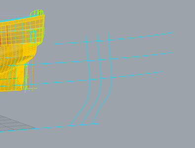
gaps between lines should be minimal
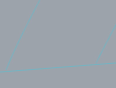
Select all the necessary lines by using a shift
Right click on "Surface from 3 or 4 corner points" icon
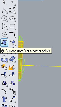
Choose "Surface from network of curves"
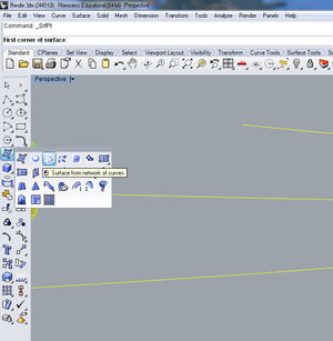
if the network is assembled without gaps, you will see such a message.
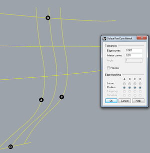
Result
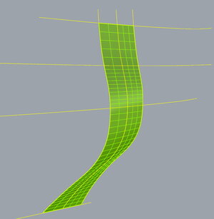
Good luck!
Last edited:
Dear Oleg thanks for this detailed tutorial. Then I see that besides the frames I also have to draw waterlines also to obtain a closed surface.
I’ll be following your log
Best Regards from Turkey
I’ll be following your log
Best Regards from Turkey
- Joined
- Sep 7, 2020
- Messages
- 27
- Points
- 78

It's not obligatory. In the case of simple contours, such as on a yacht model, the keel and deck lines may well be sufficient. Rhino sometimes has his own ideas about approximation and you can add waterlines only if the initial result does not suit you.Then I see that besides the frames I also have to draw waterlines also to obtain a closed surface.
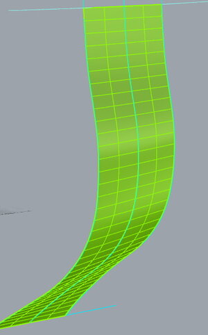
Dear Bilal - I love you Montanes
 . And it seemed to me that the framework of the kit model is already a little cramped for you
 Тише едешь, дальше будешь...Олег, как успехи?
- Joined
- Sep 7, 2020
- Messages
- 27
- Points
- 78

So - a small update:
Sheathed the transom, experimenting with a convex surface and imitation of caulking with ink mixed with glue: I don't really like the caulking result yet - I'll look at the overall impression later.
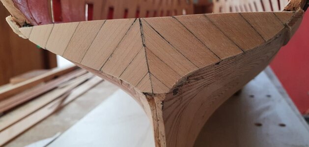
And then suddenly the strongest sharaf happened - with a sharp drop in humidity: half an hour after I took the model out under the shed, something happened that scared me a lot - one of the glue seams between the sections burst and the gap grew to almost one and a half millimeters!
I was so shocked that I didn't even take a picture of this horror.
Fortunately, it was enough to bring the model into the house and wait a couple of hours for the wood to acquire volume and the seam to tighten. In the photo you can see the temporary longitudinal reinforcement of the gluing between the sections at that location.
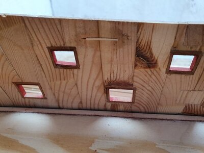
It became clear to me that it was urgent to sheathe the sides of the ship, until the deformations of a thin layer of pine led to something even worse.
But I had to start with the drawings: when calculating the cladding, I discovered some of the features of St. Albans that I missed earlier, namely the 2 upper ports in the main mast channel board area (exactly those whose decorative wreaths are located above the line of the rest of the wreaths).
The one closer to the stern (2) did not raise any questions - it was just necessary to glue the lower part of the port flush with the channel board upper line. With the next port (1), everything turned out to be more interesting: its lower part is also beveled parallel to the channel board, but is slightly higher than it. Such a strange shape of the port is apparently explained by the desire not to hurt when opening yufers, installed opposite.

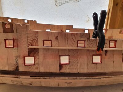
The situation was worse with the port next to them: on the main drawing and on both models, it looks displaced downward relative to the entire line of ports on the main deck (At the same time, in the interior layout drawing, all ports are drawn at an equal distance from the decks.).

No matter how much I looked for a rational explanation for such a strange solution in every sense, nothing came to my mind except for an unintentional mistake of the author of the original model.
I've decided to keep this port in line with the others for now, but I'll be glad if someone can shed some light on this oddity.
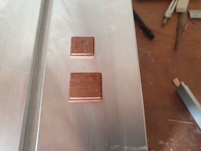
I also had to spend a lot of time adjusting the height of all ports: I initially wanted the doorposts of the ports to protrude half a millimeter (in real scale about an inch), but with a skin thickness of 1.5-2 millimeters, this size is difficult to maintain and does not look very good. I had to accumulate jambs on all ports.
A couple of templates for ports fitting.
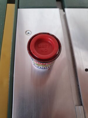
At the same time, I picked up an ocher paint from my stocks. Although it is designed for plastic, to my surprise, it fits on the wood perfectly.
Sheathed the transom, experimenting with a convex surface and imitation of caulking with ink mixed with glue: I don't really like the caulking result yet - I'll look at the overall impression later.

And then suddenly the strongest sharaf happened - with a sharp drop in humidity: half an hour after I took the model out under the shed, something happened that scared me a lot - one of the glue seams between the sections burst and the gap grew to almost one and a half millimeters!
I was so shocked that I didn't even take a picture of this horror.
Fortunately, it was enough to bring the model into the house and wait a couple of hours for the wood to acquire volume and the seam to tighten. In the photo you can see the temporary longitudinal reinforcement of the gluing between the sections at that location.

It became clear to me that it was urgent to sheathe the sides of the ship, until the deformations of a thin layer of pine led to something even worse.
But I had to start with the drawings: when calculating the cladding, I discovered some of the features of St. Albans that I missed earlier, namely the 2 upper ports in the main mast channel board area (exactly those whose decorative wreaths are located above the line of the rest of the wreaths).
The one closer to the stern (2) did not raise any questions - it was just necessary to glue the lower part of the port flush with the channel board upper line. With the next port (1), everything turned out to be more interesting: its lower part is also beveled parallel to the channel board, but is slightly higher than it. Such a strange shape of the port is apparently explained by the desire not to hurt when opening yufers, installed opposite.


The situation was worse with the port next to them: on the main drawing and on both models, it looks displaced downward relative to the entire line of ports on the main deck (At the same time, in the interior layout drawing, all ports are drawn at an equal distance from the decks.).

No matter how much I looked for a rational explanation for such a strange solution in every sense, nothing came to my mind except for an unintentional mistake of the author of the original model.
I've decided to keep this port in line with the others for now, but I'll be glad if someone can shed some light on this oddity.
I also had to spend a lot of time adjusting the height of all ports: I initially wanted the doorposts of the ports to protrude half a millimeter (in real scale about an inch), but with a skin thickness of 1.5-2 millimeters, this size is difficult to maintain and does not look very good. I had to accumulate jambs on all ports.
A couple of templates for ports fitting.

At the same time, I picked up an ocher paint from my stocks. Although it is designed for plastic, to my surprise, it fits on the wood perfectly.

- Joined
- Sep 7, 2020
- Messages
- 27
- Points
- 78

For the wales patterns I now decided to use plastic - it more easily takes the desired shape and does not stick.
The plastic itself i found in the nearest building materials store in the form of boxes for electrical wiring.
Well, a few pictures to illustrate the skinning process starting.

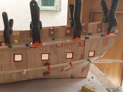

To be continued...
The plastic itself i found in the nearest building materials store in the form of boxes for electrical wiring.
Well, a few pictures to illustrate the skinning process starting.


To be continued...
Арчи, коллега, ну что же вы так Баунти не любите? И почему Баунти, это не серьёзно?Надеюсь, вы в правильной степи. Я рад что хоть кто-то верьёз занялся 17м веком (вместо очередного "Баунти"), сам очень люблю эту тему.


