Saint Albans 1687 in Navy Board Style - 1 : 48 scale [COMPLETED BUILD]

Joined
Nov 4, 2018
Messages
162
Points
253

Location
Unterföhring Germany
It took long time to decide which project I should undertake next.

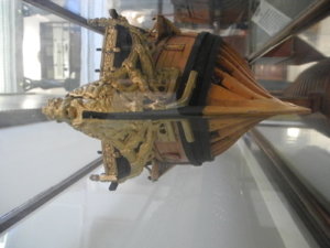
Inspired by plans, drawn by Herbert Read in 1926, I began modelling the St Albans of 1687. This was a 50-gun ship. Robert Spence was the owner of the original model and he built a copy of the model in the 1940s. I wanted to do the same, too. A model after the original model.

Spence presented the original model to the Trinity House and sold the copy of the model to the NMM in 1944. The copy carries the NMM-Number SLR0376
The Trinitiy House kindly gave me permission to visit and photograph the original model of the Saint Albans. This was very valuable as Herbert Read's plans leave some questions unanswered.

A copy shop printed the plans onto transparent plastic film at the scale of 1:48. This is the best way to bring together the different plan views.

DSCN1031.JPG

I designed the frames on transparent drawing paper. The position of the wales, clamps and stringers I drew in different colours - they have to be one hundred percent correct.

DSCN1032.JPG

For these drawings a light table was very helpful, which I actually bought to sort slides.

DSCN1030.JPG

A jig was built from a multiplex plate and from poplar plywood.

DSCN1033.JPG

The wood for the frames should be pear.

The planking itself should then be built from boxwood in the typical yellowish hue.

DSCN1035.JPG

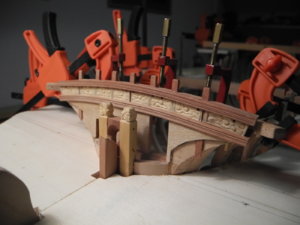
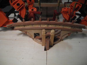
In the meantime I started to make the keel and the deadwoods. I have built these components in two halves, which makes sawing and grinding pretty easy. I suspect that this method was used for the original model.

DSCN1028.JPG

DSCN1036.JPG

DSCN1037.JPG


Cheers, Alexander
 
Last edited:
Hallo my friend,
I am very happy, that you decided to start your building log here in our forum.
A warm welcome here on board - we are looking forward to see your project growing.

For all others:
Alexander was also last year in Rochefort where I met him.
He participated in the exhibition with a small amazing barge, take a look here


IMG_11621.JPG

Now you know, what we can expect here in this topic of his new project.

BTW: Very interesting start ....... Hope to see updates as often as possible
 
Thanks for the friendly reception at SOS. I'm already a bit further with the construction. But now I'm going on vacation, then I'll continue reporting.

Cheers, Alexander
We wish you a nice and relaxing holiday - and we are looking forward to see your work on this interesting ship.
 
To give you an impressiona about the Saint Albans here are the plans:

SeiteAußenKL.jpg

SeiteInnenKL.jpg

DeckKL.jpg

Bug und HeckKL.jpg

QuerschnitteKL.jpg


Thanks to Mr. Neil Jones, I was able to view and photograph the original model. He kindly gave me permission to publish the pictures. So here are some pictures that I could do in London:


DSCN0872.JPG
DSCN0833.JPGDSCN0848.JPG

DSCN0864.JPGDSCN0857.JPG

Cheers, Alexander
 

Attachments

  • DSCN0838.JPG
    DSCN0838.JPG
    203.9 KB · Views: 36
The plans lack the concrete numbering of the frames, so unpleasant surprises could threaten. So I started to build the rear area with provisional frames made of poplar plywood. So I could also gain some experience on the fitting of the frames in the deadwood: It is not so easy! Then I installed the transom as a dummy. The first disillusionment: The frames do not fit! Their position was wrong.

DSCN1054.JPG

In addition, I realized that it is impossible to prefabricate the frames accurately enough, to "plug and fit". But that would be the requirement, because the hull has insufficient stability by the lack of support of the neighboring frames. Not before the keelson and stringers are installed, the construction will be stable enough. And at this point, it is already too late to make any significant corrections to the frames. So I have to build the frame constellation, withe every part removable and alterable. Gluing is taboo until final preparation of the frames.

DSCN1051.JPG

Somewhat discouraged, I went to the front frames. Fortunately these are consistent with the geometry of the hull and also correspondent to the images of the original model. So I just had to redesign half of the frames. ;)

In the meantime, I also had enough time to remember the multitude of brass nailings that can be seen on the original model. Then I came up with the idea to mount the frames with brass pins as long as I am not shure about their final form. That's just theory. Let's see if it works.

With the new drawings (new frame positions aft of the mainframe) and the 7.1 mm thick pearboard, which has been prepared by a carpenter, I tried my luck at the rear again. With a pin knife I made 1.5 mm and 1.2 mm thick pins.
1.) Now it fits with the dummytransom, the hull shape seems to be correct so far.
and
2.) The construction can be easily solved again and further modified.

DSCN1053.JPG
In order to get the most accurate transfer of the plans of the frames on the wood, I copied these and stuck them with rubbercement (Fixogum).
DSCN1055.JPG

Here you can see the position of the pins.

DSCN1056.JPG

Cheers, Alexander
 
Last edited:
Hallo Alexander,
You started here a very interesting model - especially the way of the framing will be a challenge (like you already described in your text.
Many thanks to show us in the beginning the drawings and the contemporary model - so we know, what we can expect.
Good idea with the pins for the temporary connection - I hope, that this way will work for all the framing work.
I am looking forward .......
 
Thanks or the comliments, Uwe. Also thanks for the likes.

Some explanations about the production of pens

As already mentioned, the parts are initially connected with 1.5 mm thick brass pins. This allows me to remove individual parts from the composite over and over again. The pins make a very stable and accurate connection. Only later should the parts then additionally be glued.

To make the pins, I use a special pin knife. This is a thick steel knife with a "cutting edge" which has a fairly large angle.
DSCN1059.JPG

I take twice the length of the desired pins and separate the brass rod by quickly sawing back and forth. The outcome of the pressure is a small bead on both sides of the cutting edge.
DSCN1060.JPG

DSCN1062.JPG

When the brass rod is severed, it has a mushroom-shaped end with a fine ridge on both sides. The ridge then later guarantees a rock-solid fit as soon as it is fully hammered into the wood.
DSCN1063.JPG

The divided part is divided in the middle with a pair of pliers and then gets a nail-shaped tip sanded.
DSCN1064.JPG

DSCN1065.JPG

Next step is the keelson. I formed it according the plan over a template.
DSCN1057.JPG

The floor timbers I make of darker pear wood than the rising timber (first and second futtock are realised at the Saint Albans simplified as one part). That gives a nice color contrast. I've seen it that way at other Navy board models.

DSCN1058.JPG

Cheers, Alexander
 
Many thanks for the update - for the very interesting update!!!
The way to produce these kind of pins is a really good idea - did not know, that such a tool "pin-knife" is existing - the result is very good and will work well.
I agree with your word about the positive contrast of the different timbers.
Also on the photos of "your" contemporary model we can see, that also the modeler of this model used two different kind of timber
DSCN08331.jpg

Thumbs-Up Thumbs-Up
 
Thanks Uwe!

Meanwhile, the frames are complete as far as the 1st futtock.

DSCN1080.JPG

DSCN1082.JPG

DSCN1083.JPG

DSCN1085.JPG

Iupplemented the jig by a floor at 15 cm height and at 20 cm height in the aft section. So the area of the top of the frames should get a support. In my construction, it is important to get additional fixed points. First because of the accuracy and secondly because of the stability.
I then extended some frames to the top timbers. However, it has been shown that the installation and removal of the frames becomes very difficult. Therefore, I have decided to give up my decision to add the top timbers. I want to fair the bottom part af the hull first and after that I'll continue to install the upper parts of the frames.

It's pretty difficult to find the correct lines of the deadwoods.At the same time I incorrectly treated the aft frames and had to rebuild these frames.

DSCN1090.JPG

Now I have become more careful. It is helpful in the fairing process that it is still possible to remove the deadwoods. So the work is a bit easier. The little tool in the foreground is a mini-bevel of Crown tools. Thus, the angle between the adjacent frames can be determined and you know in which angle you have to rasp the frame.

Cheers, Alexander
 
Last edited:
Here are some pictures of the individual components and the whole then put together:

DSCN1207.JPG

DSCN1208.JPG

DSCN1209.JPG

DSCN1210.JPG

With the mini-bevel, the angle to the neighboring frames was determined. This angle applies to almost the entire length of the frame. Both on the inside and the outside - so it forms a parallelogram. So I could easily remove the angle easily from the template board of the shear line in 10 cm height at the building slip.

Only to the keel or deadwood, the angel of bevel must be reduced to 0 °. So parallel to the keel.

So this work is quite easy by the hand. However, one or the other frame had to be made several times. But that was not a major problem either.

I have already tried on the knightheads. I can not reach the quality of the carvings on the original figures. Maybe I have to train a little bit to get a fair quality of the characters. I have to carve many such heads for the Sainat Albans.


After that I have dedicated myself to the enigmatic foreship of Saint Albans ...

The plans do not include the exact course of the front frames in the upper area. The pictures from the Trinity House could not eliminate all the confusion. The original model is painted in this area with matte black color, which made a close observation difficult.

I made some attempts to get a propper match. Important in the construction is the foremost massive deck beam. Its position determines the position of the front bulkhead and the course of the clamps of the upper deck in the area of the back.


DSCN1355.JPG


This side view shows the structure of the construction

DSCN1353.JPG


The last two pictures show the shape and position of the cathead, which is also attached to the foremost deck beam. The massive dimensions of this deck beam are certainly also explained by the fact that it serves as an abutment for the cathead.

DSCN1348.JPG

DSCN1349.JPG

Cheers, Alexander
 

Attachments

  • DSCN1348.JPG
    DSCN1348.JPG
    163.3 KB · Views: 23
  • DSCN1350.JPG
    DSCN1350.JPG
    167.9 KB · Views: 24
  • DSCN1350.JPG
    DSCN1350.JPG
    167.9 KB · Views: 26
Last edited:
The rudder with its fastenings

DSCN1817.JPG

The frames are now prepared for installation. Ready-made (hopefully good enough!) Embedded on the front sides and insides with a sealing filler (Clou-Schnellschleifgrund) to protect the surface.

DSCN1816.JPG

Today I glued the frames in place. At the keel and laterally at the slipway. So the frames hold tight bombproof.

DSCN1819.JPG

DSCN1820.JPG

DSCN1821.JPG


So it's a kind of a roofing ceremony!


Greetings, Alexander
 
Last edited:
Back
Top