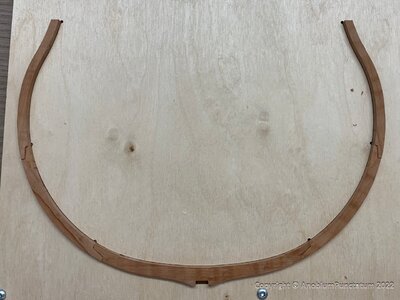
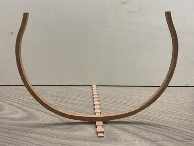
HMS Triton, 1771 - scale 1/48

On Easter Monday the time had finally come. The keel of his majesty's frigate HMS Triton was laid.

First the 5 components for the keel were sawn out.
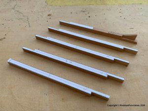
Triton-101.jpg

I have simplified the design of the joints considerably, as they will be completely covered later on by further components. I will continue to apply this principle during the further construction in order to adapt the building as far as possible to my craftsmanship.
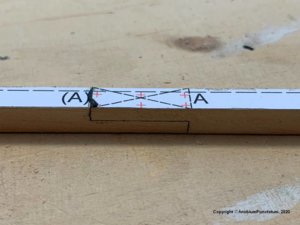
Triton-104.jpg

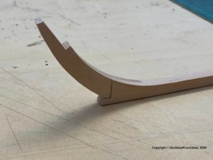
The first cliff that had to be overcome is the joint between keel and lower stem. I worked this out with my milling machine and chisels.
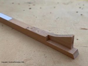
Triton-102.jpg

Triton-103.jpg

After I had attached the false keel, the joints have to be dowelled. These dowels are a bit too big for the chosen scale, but I cannot draw pear wood thinner than 0.8 mm. I know that many modellers swear by bamboo, but I find pear on the finished model more discreet.
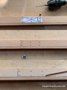
Triton-105.jpg

I have simulated the caulking with single-ply pulp.
 
Last edited by a moderator:
I remember this project on MSW 1.0 (before the crash). I initially signed up for the cross section of the HMS Triton and only built most of the frames and then stopped. I still have plans but wood habeen used for other models.

I will be following this built wkth great interest.
Marcus

Btw. I've always liked your username. Reminds me of a microbe in a petri dish, but it really is the common name for a furniture beetle.
 
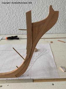
Further with the "Upper stem". There are only two parts that have to be glued to the lower part of the stem, which was already shown in the last part. The issue is complicated by the fact that even tiny angular deviations in the "Joint" lead to deviations at the upper end of the component. Aggravating is the fact that the component is about 1.7mm thicker than the keel

At first I built a small jig, which fixes the keel during the adjustment work. To check the position of the components, a template was aligned on the working surface and fixed with adhesive tape. Thin wooden plates were placed under the keel to compensate for half of the height difference.

Triton-106.jpg

Next, the two components of the "upper stem" were glued together. A little more material was deliberately left at the sides to compensate for the construction tolerances later. Then the joint between the new component and the "Lower stem" was adjusted with my milling machine, chisels and sandpaper until the upper end of the stem was in line with the template. Now the components could be glued together.

Triton-107.jpg

The old templates were removed and a new template was glued and aligned. Finally, the stem was sanded into shape.

Triton-108.jpg
 
Last edited by a moderator:
Thanks for the Likes
You're right Nigel. For job reasons I couldn't work with timber for the last 4 years. So I am really happy to make sawdust in my little shipyard.

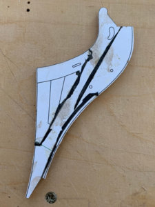
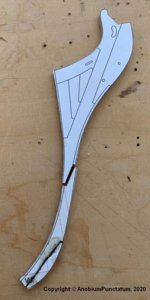
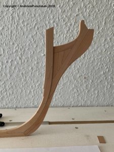
Today I prepared the "Knee of the Head". I have divided this one into two parts to make it easier for me to adapt to the stem later. First the chocks of the upper part were adjusted and glued together. For the caulking was again single layer cellulose used. To compensate for small tolerances, the templates were again exchanged for a single one after completion of the assembly. The main piece and the other components of the upper assembly were then added

Triton-109.jpg

The lower assembly was then adapted and assembled.
The following two pictures show the current status:
Triton-110.jpg

Triton-111.jpg

Since my vacation is coming to an end, the shipyard is now being exchanged for the home office. Nevertheless I hope to finish the "Knee of the Head" next weekend.
 
Last edited by a moderator:
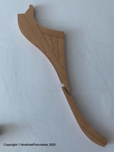
Actually, the weather is too nice to work in the shipyard...
...but a little bit I did manage to do this weekend.

The two prepared parts of the "Knee of the Head" were carefully fitted to the steven and then glued together.
Triton-112.jpg

Next, all templates were carefully removed and the fit was checked again
Triton-113.jpg

To make it easier for me to glue the Knee of the Head to the stem I drilled three holes of 2.0mm and fixed the component with brass wire. At this step the fit was checked one last time and some slight corrections were made.
Triton-114.jpg

Now the Knee of the Head was sandes into shape. It tapers from the keel to the upper corner of the leading edge from about 10.5'' (according to SR 9.5'') to 7.5''; the trailing edge has a constant width of 10.5''. To transfer the measurements to the wood, I made small templates in CAD and glued them to the component. The stern changes its width from 10.5'' at the transition to the keel to 16'' at the top edge. I have also made a template for this. Because of all the sanding I forgot to take pictures of this stage of construction.

The last three pictures show the finished ensemble. On the second last picture you can hopefully see the wooden dowels I glued to the model instead of the brass rods.
Triton-115.jpg Triton-117.jpg

Triton-116.jpg
 
Buenas tardes, estoy muy feliz de que haya comenzado con el HMS Tritón, un verdadero placer para continuar su construcción. ¿El calafateo de celulosa donde lo obtienes o lo preparas? No lo sabias. Por favor recuerde mi solicitud sobre los planos.

Good afternoon, I am very happy that you have started with the HMS Triton, a real pleasure to continue its construction. Cellulose caulking where you get it or prepare it? You did not know. Please remember my request about the plans.
 
Last edited by a moderator:
Buenas tardes, estoy muy feliz de que haya comenzado con el HMS Tritón, un verdadero placer para continuar su construcción. ¿El calafateo de celulosa donde lo obtienes o lo preparas? No lo sabias. Por favor recuerde mi solicitud sobre los planos.

Jorge, I got the pulp in a crafts shop. The drawings are not finished in the moment. You need patience. I will be sure, that it's possible to build the hull with the drawings.
 
Looking very good - very clean and accurate work

... but wrong. A member of the Arbeitskreis send me a drawing of Steel's Elements (I miss this book in my library), which shows that the used source is not correct. I tried to fix it this morning, but this was not possible. So I have to redo my work. I will send the next update after finishing the redo.
 
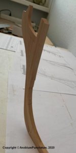
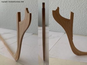
... but wrong. After finishing the ensemble I got the information that the step between stem and knee of the head doesn't exist. There is a drawing in Steel's Naval Architecture, that shows this detail. I am missing this book in my library and follwed the design of the Swan Class series by my first attempt.

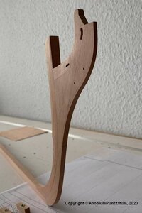
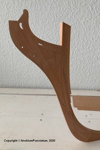
The two pictures show the reworked stem and knee of the head:
Triton-118.jpg Triton-119.jpg
 
... but wrong. After finishing the ensemble I got the information that the step between stem and knee of the head doesn't exist. There is a drawing in Steel's Naval Architecture, that shows this detail. I am missing this book in my library and follwed the design of the Swan Class series by my first attempt.

The two pictures show the reworked stem and knee of the head:
View attachment 153103 View attachment 153104
Looking excellent ThumbsupThumbsup
I will follow
 
The last two years I needed my workshop as homeoffice. Now I am back in my office which gives me the possibility to use my workshop as shipyard again.

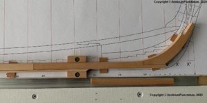
To practice I build a test frame from an old piece of wood.

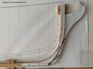
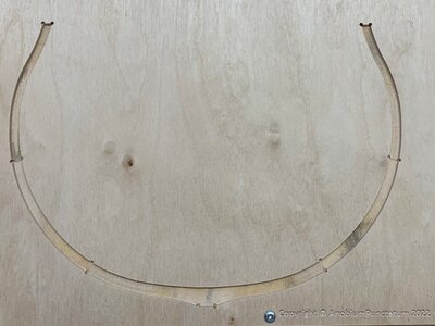
Instead of a paper base, I milled a template from plywood, which already takes into account the different thicknesses of the futtocks.
Triton-011.jpg

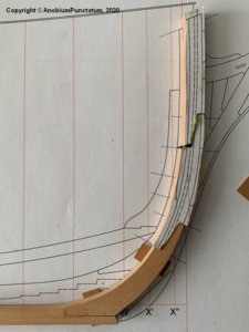
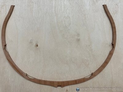
On this template, the futtocks were first glued together and then the chocks were added.
Triton-012.jpg Triton-013.jpg

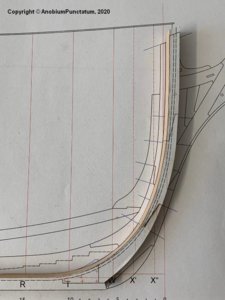
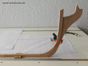
Finally a photo of the finished test-frame.
Triton-014.jpg

Now I can start with the serial production.
 
Hallo Christian,
a very interesting and I think also sophisticated way to make the frames.

This means you have to mill for every single frame such a template. And also you have to prepare cut and sand all the single elements (floor timber fittocks and top timbers) very accurate and without any or a lot of meat for later adjustments.
How you plan to handle f.e. double frames? will you glue the second side on top of the first one? or will you make a second template for the second side of the double frame and put the prepared two separate halfs together?

Sorry for all these questions......
 
Hi Uwe,

every frame is a little bit thicker than needed. This is necessary for the tolerances during the build. I used this value also for preparing the jig.
My plan is to make all frames as single frames first. In a second step I will glue the single frames fogether to create a double frame. It makes it also easier to put the necessary spacers between the frames. The English method is different than what I've seen for French ships.
I have also drawings from this period, which are showing, that the English only use single frames (for exapmles HM Sloop Cygent). In the 1770th starts an evolution of the frame design for English ships.
 
Back
Top