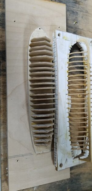
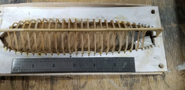
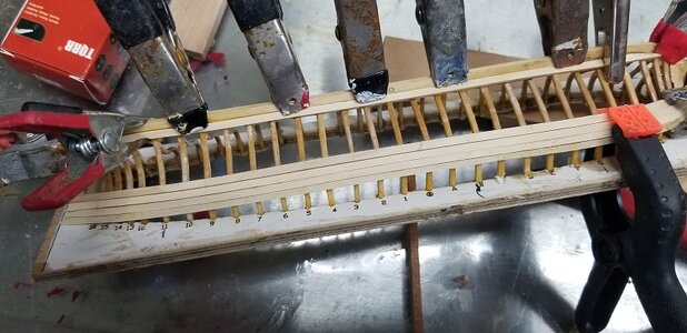
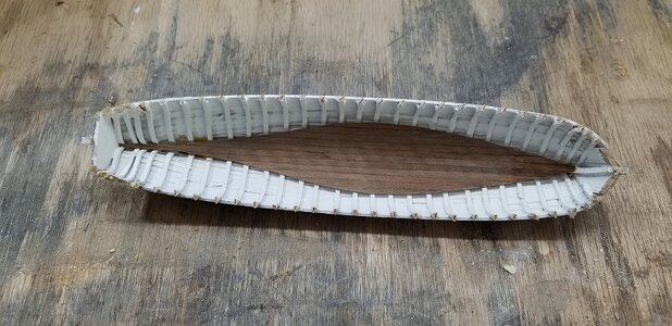
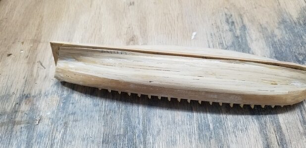
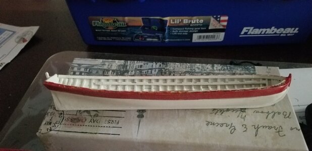
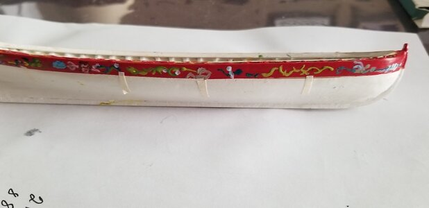
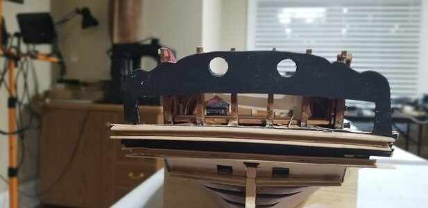
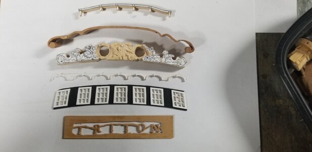
To this point I show the hull separated from the build frame. So lets talk about the decks.
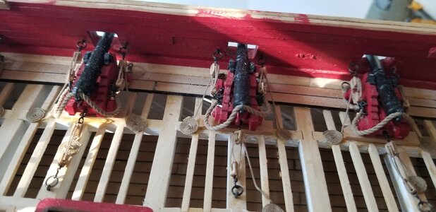
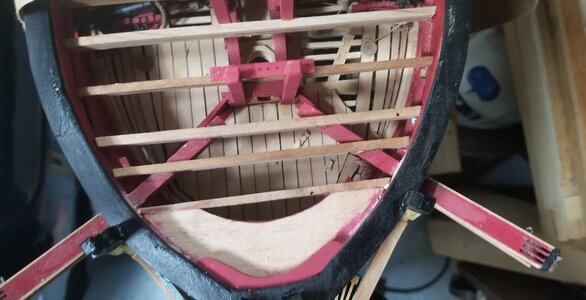
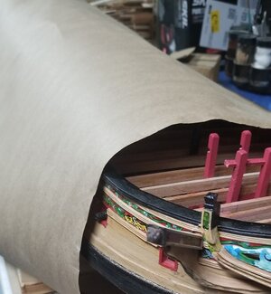
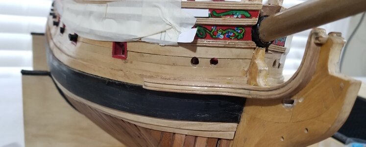
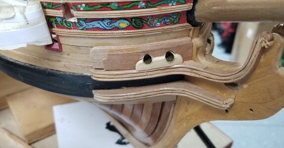
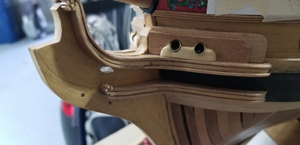
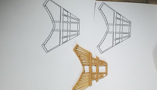
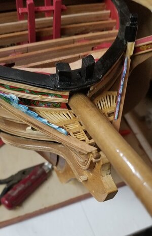
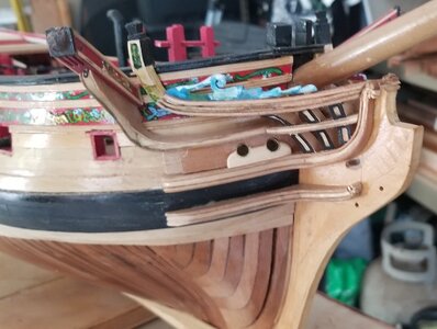
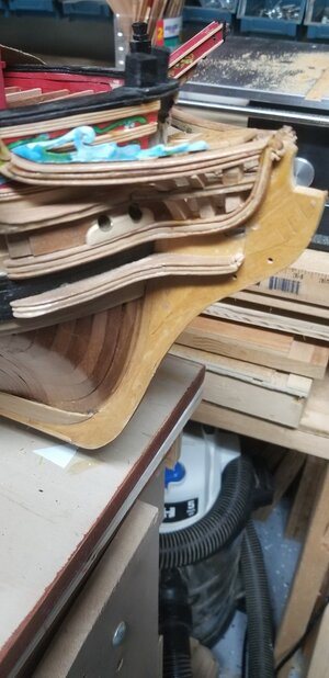
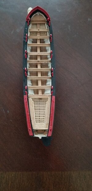
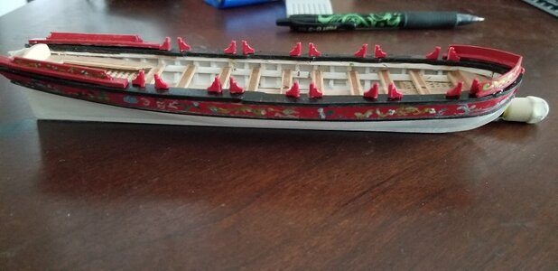
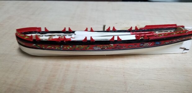
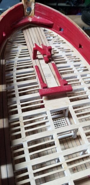
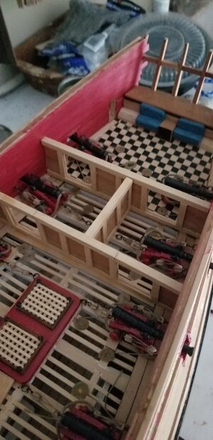
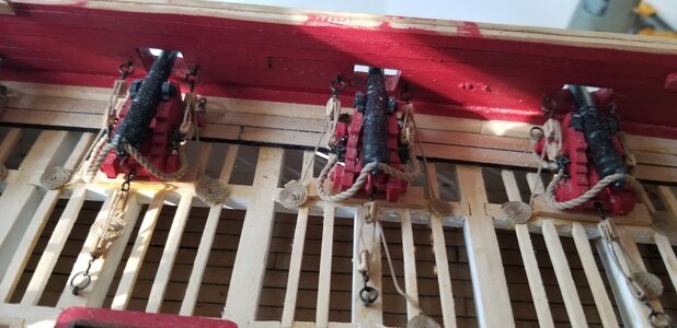
Lower Deck: There was a pattern in the drawings for the deck beams. Since there was not going to be anything truely visible I decided to put the deck beams down and fully plank over them. I used the ports to locate the sills for the deck beams. I did that with the main deck as well. I had alread constructed a prototype of a cannon. So, center of the cannon barrel to deck etc. On the lower deck itself I put in all of the stairways and hatches pillars. It also includes the spirits room, bread room and all of the lesser officer quarters. I spent much time with features no one can really view. Viewing only thru the main deck. The forecastle and quarter decks are on top of those. These two photos illustrates that.
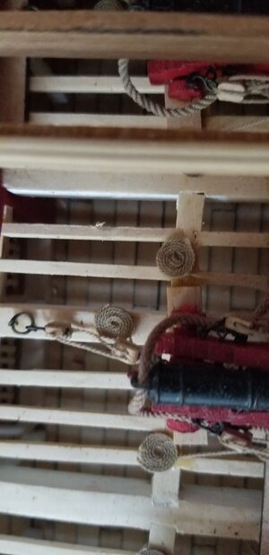
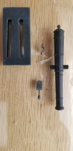
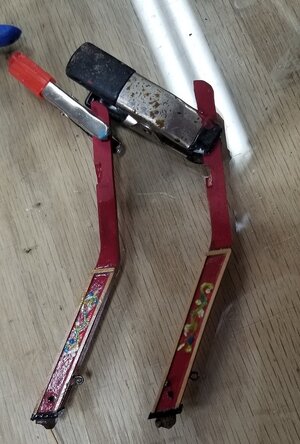
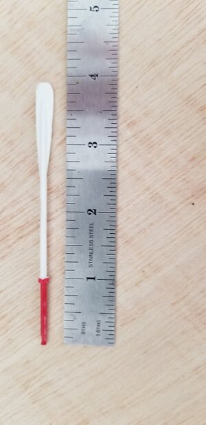
Just a segway to pillars. I should had made them 3d printed. Simple enough. Import the pillar drawing to my cadcam program. Draw and create an .stl file and print. I didn't. I decided to use my Proxxon lathe and Penn Duplicator. Square ends do not easily and accurately center on a 3 jaw chuck. at this scale. So I made two 3d printed fixtures I drew up . Basically a cylinder with a centered square hole of the proper dimension. Also a cented hole on the other end of the cylinder for the live center. See next picture:

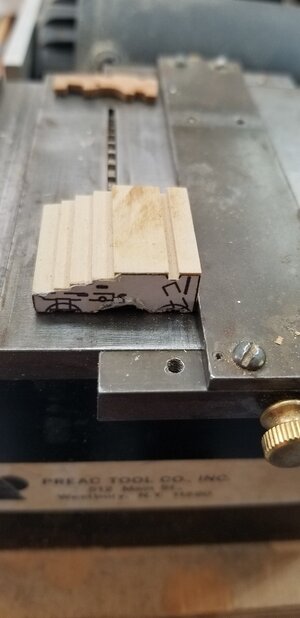
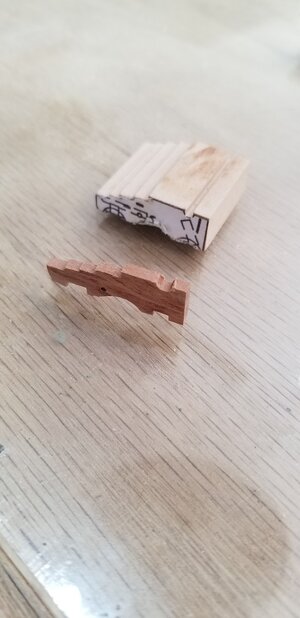
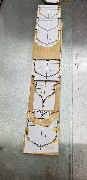
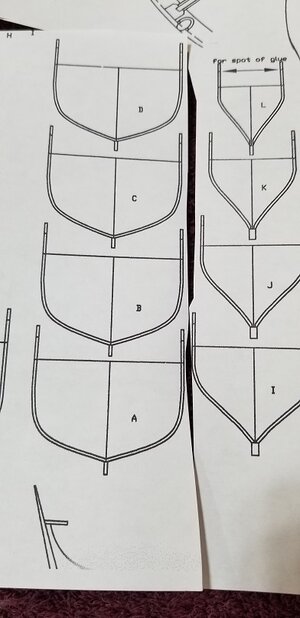
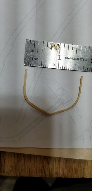
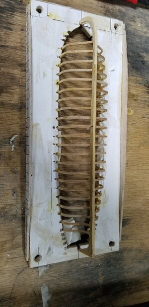
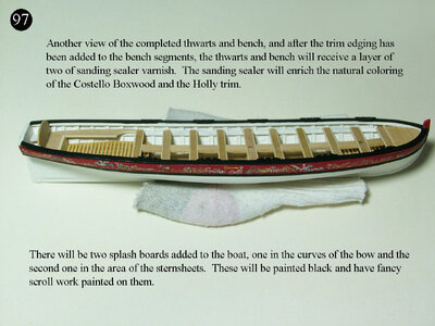
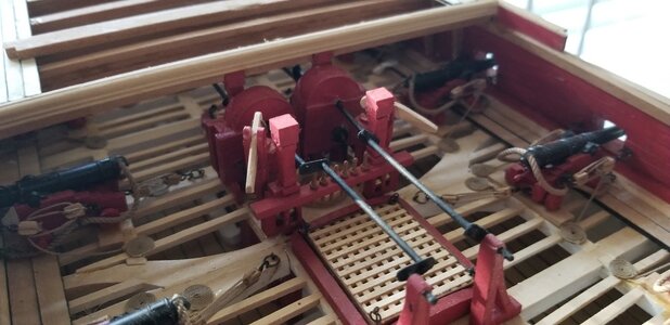
The main deck: This deck all of the real features are applied. Water cistern pumps, cannon, captain's quarters, stairs, capstan. Even the oven. The patterns for the deck beams is on one the 16 drawings I received from Romero for this build. I set the camber to the beams using the Harol Hahn method displayed in HMS Warrior books. I copied all of the beams and located all of the necessary deck beam cuts for horizontal knees, carlings, ledges.
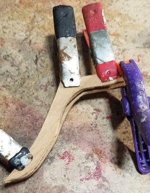
The Harold Hahn Jig: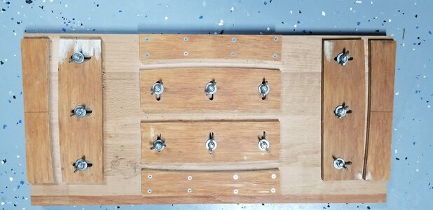
I will close this session out now. Next, Cannons
Lower Deck: There was a pattern in the drawings for the deck beams. Since there was not going to be anything truely visible I decided to put the deck beams down and fully plank over them. I used the ports to locate the sills for the deck beams. I did that with the main deck as well. I had alread constructed a prototype of a cannon. So, center of the cannon barrel to deck etc. On the lower deck itself I put in all of the stairways and hatches pillars. It also includes the spirits room, bread room and all of the lesser officer quarters. I spent much time with features no one can really view. Viewing only thru the main deck. The forecastle and quarter decks are on top of those. These two photos illustrates that.


Just a segway to pillars. I should had made them 3d printed. Simple enough. Import the pillar drawing to my cadcam program. Draw and create an .stl file and print. I didn't. I decided to use my Proxxon lathe and Penn Duplicator. Square ends do not easily and accurately center on a 3 jaw chuck. at this scale. So I made two 3d printed fixtures I drew up . Basically a cylinder with a centered square hole of the proper dimension. Also a cented hole on the other end of the cylinder for the live center. See next picture:

The main deck: This deck all of the real features are applied. Water cistern pumps, cannon, captain's quarters, stairs, capstan. Even the oven. The patterns for the deck beams is on one the 16 drawings I received from Romero for this build. I set the camber to the beams using the Harol Hahn method displayed in HMS Warrior books. I copied all of the beams and located all of the necessary deck beam cuts for horizontal knees, carlings, ledges.
The Harold Hahn Jig:


I will close this session out now. Next, Cannons
Last edited:


