HMS Triton Build Log

To this point I show the hull separated from the build frame. So lets talk about the decks.
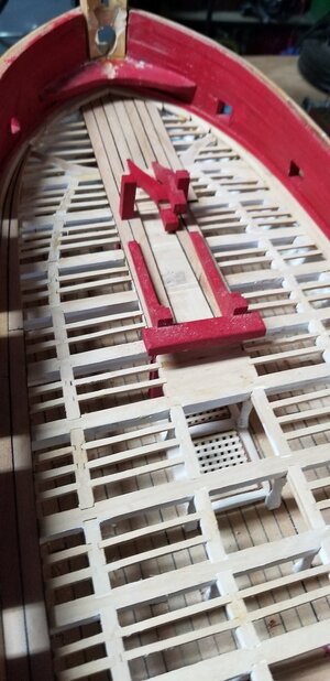
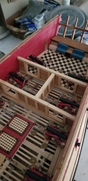
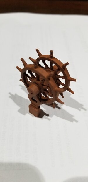
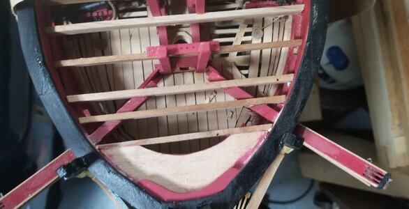
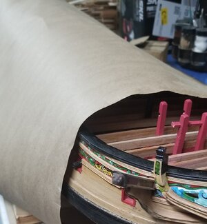
Lower Deck: There was a pattern in the drawings for the deck beams. Since there was not going to be anything truely visible I decided to put the deck beams down and fully plank over them. I used the ports to locate the sills for the deck beams. I did that with the main deck as well. I had alread constructed a prototype of a cannon. So, center of the cannon barrel to deck etc. On the lower deck itself I put in all of the stairways and hatches pillars. It also includes the spirits room, bread room and all of the lesser officer quarters. I spent much time with features no one can really view. Viewing only thru the main deck. The forecastle and quarter decks are on top of those. These two photos illustrates that.
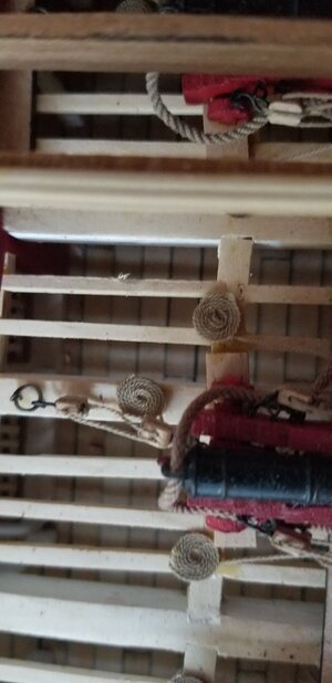
20240129_154249.jpg20240129_154313.jpg

Just a segway to pillars. I should had made them 3d printed. Simple enough. Import the pillar drawing to my cadcam program. Draw and create an .stl file and print. I didn't. I decided to use my Proxxon lathe and Penn Duplicator. Square ends do not easily and accurately center on a 3 jaw chuck. at this scale. So I made two 3d printed fixtures I drew up . Basically a cylinder with a centered square hole of the proper dimension. Also a cented hole on the other end of the cylinder for the live center. See next picture:
20230702_074115.jpg

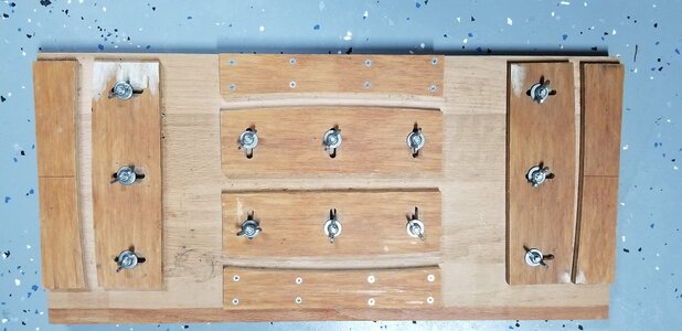
The main deck: This deck all of the real features are applied. Water cistern pumps, cannon, captain's quarters, stairs, capstan. Even the oven. The patterns for the deck beams is on one the 16 drawings I received from Romero for this build. I set the camber to the beams using the Harol Hahn method displayed in HMS Warrior books. I copied all of the beams and located all of the necessary deck beam cuts for horizontal knees, carlings, ledges.
The Harold Hahn Jig:20231216_083418.jpg
20230709_194216.jpg20231010_165956.jpg
20240129_152055.jpg20240129_152044.jpg


20231024_211648.jpg

I will close this session out now. Next, Cannons
 
Last edited:
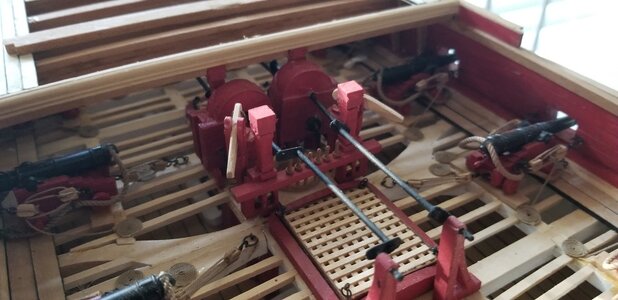
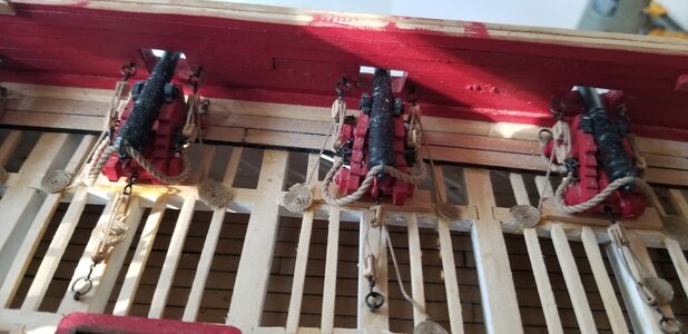
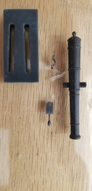
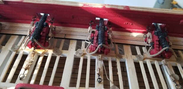
Cannons, every good Frigate needs cannons. There are twenty four (24) 18# cannons on the main deck of the Triton. All essentially made from scratch. I used wood for the carriage frames. I 3D printed the cannon barrels, wheels, axles, quiouns, trunion clamps. They will be shown in the pictures. Ropes, eye bolts, rings are hand fashioned. Blocks I bought. The parts came from one of the Romeo pdf plates.

First the cannon barrels. I ran two sessions to allow me to take the best reproductions. The profile was imported as a pdf to me cad program. The barrel's profile was traced. The trunion was added as a circle on the 2d tracing. Making it 3d from ther is a simple process. The circles were extended as rods from the center line. The profile was revolve 360 degrees. And there is a cannon barrel. Save it as an .stl file. The .stl it loaded to the slicer program, resized proportional and printed on my Elegoo MARS II printer.
I chose to 3d print for accuracy and superior detail rather than run them on a lathe with a Pen duplicator. Probably a time saver. The master is completed and exported to an .stl file. The master can be reproduced and all 24 printed at the same time.
My lathe is a Proxxon with an attached Pen Duplicator. I have never been thrilled with the results fron the duplicator. It only has two style of cutters tips available and they are unique to the duplicator. Fuzzies and inaccuracy.


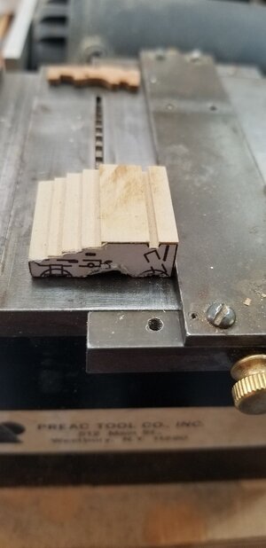
The Gun carriage is made from costello boxwood. That was profiled from the drawing. I put the pattern on 2" blocks. Using my PREAC saw with a .063 blade the profile was cut into the block using the PREAC fence. They were cut into 3/32" wafers. Holes drilled for eye bolts.

For assembly I used a little fixture I 3D printed to align the sides. They are not parellel. I used CL glue for assembly of all of the parts.

For 24 assemblies I used 24 assembled carriages, 24 gun barrels, 24 quiouns (triangual piece with a handle), 48 trunion clamps, 192 1/32" eye bolts, 192 3/32" rings, 120 double blocks, 120 single blocks.
20240130_123026.jpg20240130_123119.jpg20240130_123141.jpg20240129_152044.jpg
I used 2 sizes of ropes. I have a classic rope walk. 3 strands of MARA 30 for the smaller rope. 3 strands of smaller rope twisted for the breach ropes. (BTW) the cannons are no longer this dirty. )
 
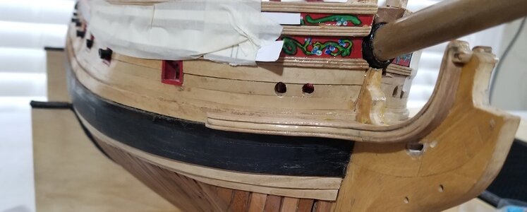
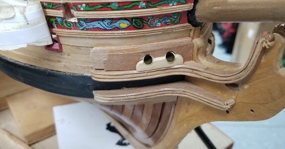
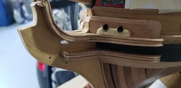
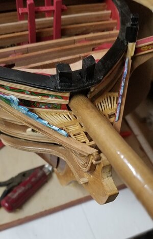
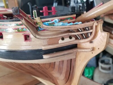
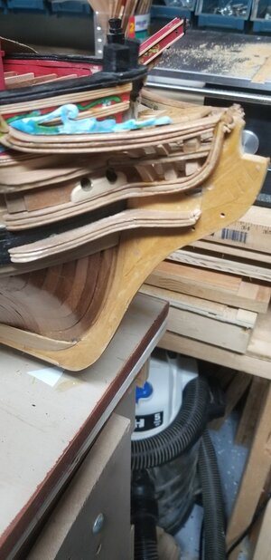
My next installment on my Triton Model are the Headrails. It took several tries and several months to complete. Yes, both sides.
I started with the catheads. The process required breaching the side of the hull. Calculating the angles and assembly. I attempted to photograph the lion's head on the cap. It's carved from 1/4 x 1/4 stock.
20240217_140408.jpg20240411_195603.jpg20240411_205202.jpg
 
Headrails 2. The second part were the rails themselves. I certainly took 3 tries plus on each of these assemblies.
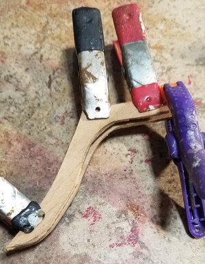
Starting with the stem knees, hawser, hawser lining, cheeks, splash board. Cathead support knee, ekeing rail, upper and lower head rails. Three sets of stem timbers, head beams and carlings. One of the reaccuring issues in following the practicum is that each ship is unique and using the patterns is almost worthless. In many cases I use Cadcam to import a pdf, size and redraw. This part was frustrating. When I look at these photos I am disappointed in the fit and finish of some of my work in the model. In between sessions on the headrails I worked on the 32' Pinnace. That will be my next installment. Got nearly 3 years in so I'm moving forward.
Wait until I have to carve figures. Figurehead, Stern etc. I'll add additional clownishness to this model. :(.


20240123_130705.jpg20240123_130643.jpg20240124_161335.jpg20240214_085612.jpg20240214_085619.jpg20240411_175019.jpg
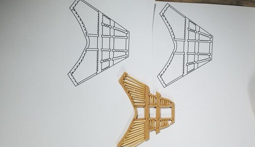
On the head decking I sized the assembly as I mentioned using cadcam. Fit it and assembled it on the template. The small sticks are 1/32 x 1/32 just to give you context in size. The two drawings following are the final product.

20240413_113152.jpg20240416_143253.jpg.

20240411_175110.jpg
 
Last edited:
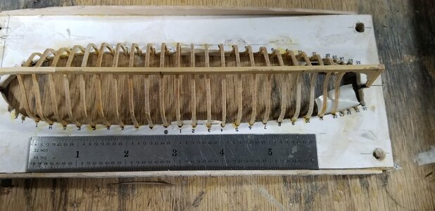
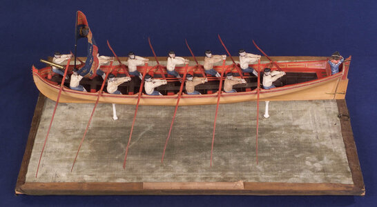
This installment is a pause from the main ship and focuses on the 32' Pinnace. I followed the patterns and instructions given to me by Romero. The follow the same patterns as in the Warrior Practicum. The only deviation are the frame construction. The Warrior uses a laminate and the Triton uses one layer.
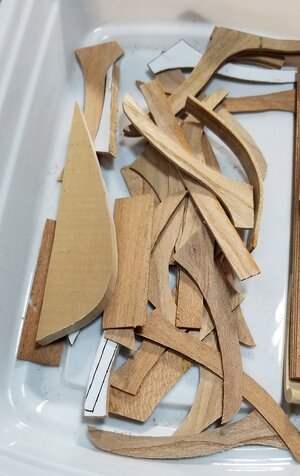
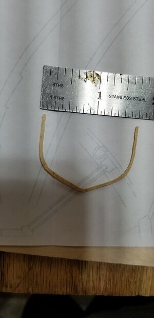
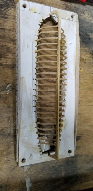
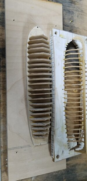
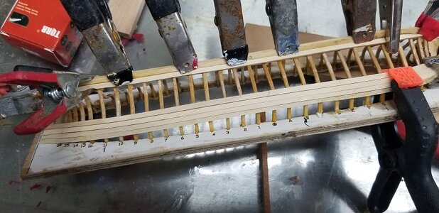
Frames are really fragile as one piece. Cutting a 1/32 frame fron 1/16 stock. The frames were cut on a scroll saw using a #2 blade at the machine's slowest speed. I cut sets four times. #1 set = Cherry. Too fragile. I settled on Paumarfim for the other three. I set I tried coating with epoxy resin. That didn't add any strength strength to the frames and it became problematic when planking the hull. The third sen is partially planked. I made some mistakes and I abandoned that set and started a fourth. The fourth I completed a reasonable planking. When plaking I found that the frames themselves only really guided the planking. The frames were the true strength in hull shape and strength. Realizing this I kept broken frames and glued them back in later. Best is to keep breakage to a minimum. However breaking a frame or two is not fatal. There's enough cover detail.
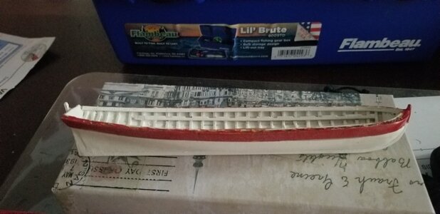
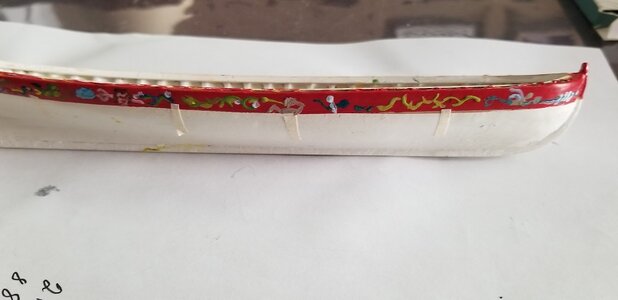
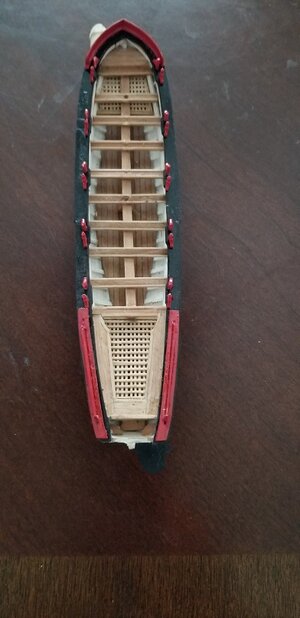
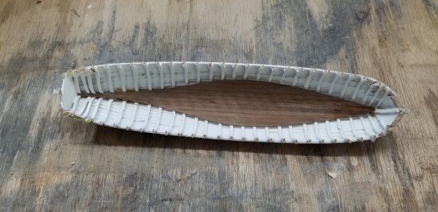
Ok, so Framed, planked I moved onto the hawser. These were simple. I pre-glued the timbers with a presanding attached the two sides to the keel. At this point the assembly is removed from the construction board. Attached the inner gunwale. The Pinnace is now painted using white spray paint inside and out.
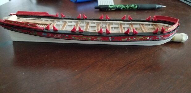
Comstructed the floor using 1/32 thick cherry with the bottom most waterline for a pattern. Floor gratings uses the same jig as hatch gratings. Floors, gratings, seats are now attached.
The upper three planks are painted red. My ham handed attempt at painting friezes are now applied.
Upper railing and oar locks are 3D printed.
Splash boards are constructed, painted red, painted scrollwork.
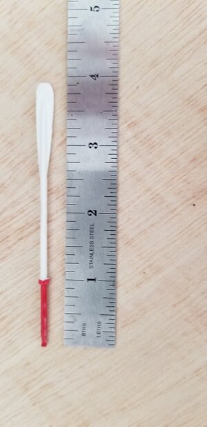
Oar construction uses 3/32 wood dowels (swizzel sticks) sanded to a point and split. The paddle was profiled on a sander as a block then sliced into 1/32 thick pieces. Paddles were sanded to a point on the flat side inserted the wedge into the split. glued, sanded and painted. VUELA!!
So now the hard parts. Finishing this model. If I'm fastideous enough I can complete in a year. A lot to do................... .


20230922_114004.jpg20230922_114023.jpg20230922_114225.jpg20231006_062831.jpg20231006_062858.jpg20231006_063001.jpg20240217_142549.jpg20240325_121357.jpg20240325_121405(0).jpg20240401_185642.jpg20240425_111355.jpg20240526_140856.jpg20240530_111542.jpg20240526_140919.jpg20240530_054738.jpg
 
Hi Bill,
Hope you don't mind my asking but which plans did you use for the pinnace? The reason I ask is that the boat has ten thwarts but only tholes for rowers on five of the them.

I know some of the contemporary plans for boats do cause confusion. at least for me at times. Every thwart had a single thole if single banked and a pair if double banked. I was lucky to discuss this drawing inconsistency/confusion years ago with Jeremy Michell when he was curator of Historic Plans and Photographs at RMG and my comments are based on these discussions.

One example of single banked plans can be seen at https://commons.wikimedia.org/w/index.php?title=Category:Ship_plans_of_the_Royal_Museums_Greenwich&filefrom='Union'+(1811)+RMG+J1706.png#/media/File:32_ft_Pinnace_RMG_J0859.png
Plan ZAZ 7190 is broad enough that may have been double banked and if that is the case, every thwart has tholes. https://commons.wikimedia.org/w/index.php?title=Category:Ship_plans_of_the_Royal_Museums_Greenwich&filefrom='Union'+(1811)+RMG+J1706.png#/media/File:32_ft_Pinnace_RMG_J0847.png

One of my favorite plans for a 32 foot pinnace can also be found on the Wiki Commons site in high resolution. One of the things I love about this drawing is that all the scantlings are given. https://commons.wikimedia.org/w/index.php?title=Category:Ship_plans_of_the_Royal_Museums_Greenwich&filefrom='Union'+(1811)+RMG+J1706.png#/media/File:32_ft_Pinnace_RMG_J0864.png

Allan
 
Last edited:
I replied to the e-mail. Realizing that I could not answer in that way.

Allan, I have a set of drawings. 16 (36 x 52) sheets that detail all of the features of the Triton. With the drawings came cd's that narrate and display techniques for build. It is an offspring of and follows (almost) all of the fundamentals displayed in the Warrior Practicum series. On the placing of the oar locks. I really never gave it much thought. I have to believe two thwarts to an oarlock. Here is a pic from the CD
32pinnace97.jpg
 
Thanks Bill,
I may be dead wrong but I am pretty sure the drawings are incorrect if they show the tholes as seen in the photo above. Again, there is often confusion in this due to the format used on some contemporary drawings. From what I have been able to research, pinnaces were never set up to be double banked. They were single banked, but even if they had been modified to be double banked they would not have empty thwarts with no rowing capabilities between the thwarts that did have tholes.

I totally understand how this layout is sometimes done, as some contemporary drawings show only an elevation view that could cause the viewer to believe the boat was set up as you show in the photo above. If you have not seen it, maybe look at the topic https://shipsofscale.com/sosforums/threads/building-a-ships-boat.14490/ especially post #55 that goes into this common mistake.
Allan
 
Allan, Ok point taken but you also say you could be dead wrong. and, I do not see empty thwarts. I see two opposing thwarts with one oar lock between them. 10 seats, 5 oar locks. I rely on the authors to provide proper accuracy. I do not have the depth of knowledge to challenge their voracity. Btw, Vanguard Models offers a 32' Pinnace model for $48 bucks and it is diplayed as my picture. See it here: https://www.historicships.com/product/32ft-pinnace/ Harold Hahn's Alfred has a 28' Pinnace. His drawing is configured as above.
 
Last edited:
10 seats, 5 oar locks.
Hi Bill,
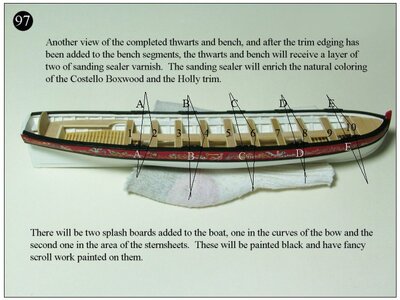
Sorry Bill, I am confused. :( In the photo below there are 10 oarlocks, two each, A through E and 10 thwarts numbered 1 to 10. There is a pair of tholes/oarlocks for the even numbered thwarts but nothing for the odd numbered thwarts. That being the case what are the 5 odd numbered thwarts for? This thole set up is for five rowers with two oars each or two rowers on each of the five even numbered thwarts with one oar each, neither of which was done on a pinnace. I have great respect for Hahn and Vanguard but I still find it beneficial to research contemporary sources to confirm or correct, as may be the case.
Cheers
Allan
Vanguard pinnace tholes.JPG
 
To end your confusion. I meant to say 5 pair. Obvously there are 10 total. BTW, Show me a picture of a Pinnace in the configuration you subscribe. I haven't seen one.
 
Show me a picture of a Pinnace in the configuration you subscribe. I haven't seen one.
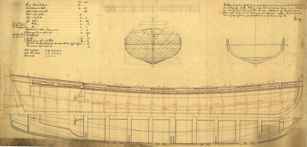
Sorry for the late reply. Every contemporary pinnace drawing I have seen to date has one thole for every thwart. In the first drawing note the top view shows alternating tholes. The drawing is old but if you look closely you can see every other thole in red ink in the elevation view, indicating they are on the port side.
31 foot PInnace from Danish Archives.png
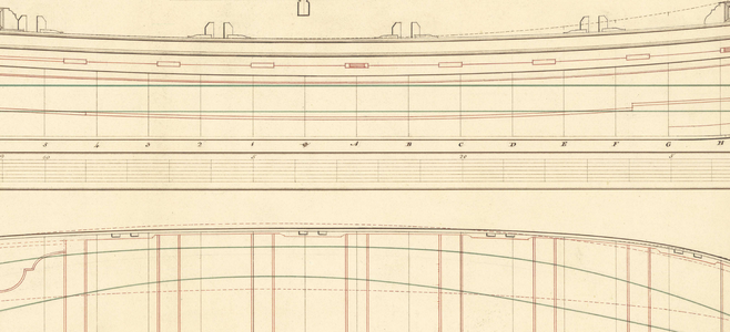
From RMG collections website this contemporary drawing shows the port tholes in the overhead view.
Tholes B.png
I think the confusion comes from other contemporary drawings that assume we know there are no thwarts without a thole so they show one set of tholes in the drawings. There were no boats with thwarts that did not have either one thole or if broad enough (over 7 feet) a pair for every thwart. In general pinnaces had one thole for every thwart alternating port and starboard. An example of a drawing for an 8 oared pinnace from RMG that shows only half the tholes follows. The number of oars is called out in the first line of text. With a breadth of only 6 feet 4 inches, there is no way it could be rowed double banked and get good leverage on the oars.
Allan
28_ft_Pinnace_1799 RMG_J0861.png
Single banked model from 1750 below
Single banked rowers.jpg
 
Last edited:
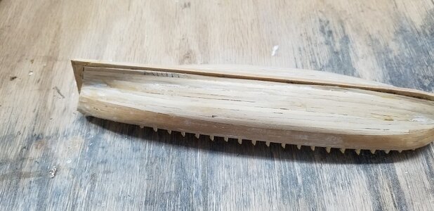
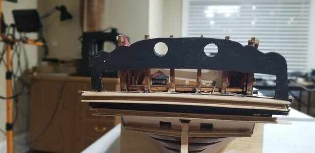
This portion of the Triton build will attemp the stern features. Here is where there is true artsy portion of ship building. I thought friezes were going to be hard. They were't so bad. Carving a convincing feature is (for me) really hard. The carvings I have never attempted. We'll see what happens. Here you can see my ham handed start.
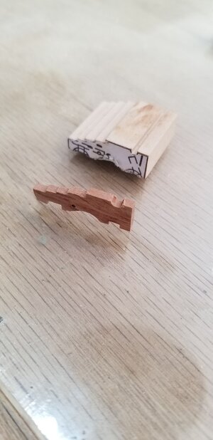
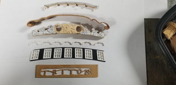
So here you see the stern all framed out and ready for it's jewelry. The second picture are all of the components roughed out. Some deviations to be noted: the windows and their crowns are 3d printed. The Triton lettering is roughed out on 1/16 boxwood and cut with a scroll saw #2 std. blade at the slowest speed. My scroll saw is about 105rpm. The stern posts will be cut off and the ends will be dummied in to the cap rail. Everything else follows the Triton practicum roadmap. It looks like all that is to be done is snip-snip here, a little glue and paint and it's done. Oh, and the master carving.
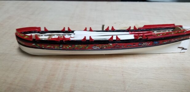
There's golfing to be done, so, hopefully I'll be back the end of summer (or sooner) with results.

20240615_062801.jpg20240615_062945.jpg
 
The Triton lettering is roughed out on 1/16 boxwood
Hi Bill,
Carving can be fun and frustrating. Yours looks to have a great start! Are you using chisels or burrs? Making the name for the stern as you have done is fun and many of us have done it because it looks great. On the other hand, just as a point of interest, not a critique in any way, the RN did not allow the names on their ships in the age of sail except between 1780 and 1790 and then they were only to be painted. If I remember correctly the letters were to be no more than 12 inches high.
Allan
 
Back
Top