HMS Victory 1:90 build log (mamoli)

Joined
Feb 10, 2021
Messages
33
Points
48

Location
Mexico
With this post I am opening my build log of the HMS Victory.
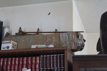
On the first picture you can see a cardboard box on the top of the bookshelf, the hull that I started years ago its there waiting to be revived.
I am starting from step 0. Which is to study the plans.

The Endeavor I made, I did it at my dad's house, but now little grandson lives there, too dangerous with a kid, and I could only go on weekends. So this time that is not possible.
I have space restrictions, so there will not be a special room for the shop, so before I unpack the materials, tools and the hull, because I will work on the center table (1mt x 1 mt) of the living room and/or on a table that is outside (not covered), I need to find out how/where I am going to store the tools, how/where I am going to store the material, how/where I am going to handle those large diagrams and where I will put the ship. All that in such a way that I can make progress on the work, and put away everything regardless of where I am working

The solution I found for the large diagrams is to copy them, advantages:
1) Helps on the studying phase
2) Not need spread out a large paper to read the instructions.
3) Have a larger font size so the reading is easier.
4) Build it on my mind while I copy

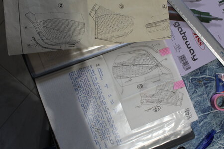
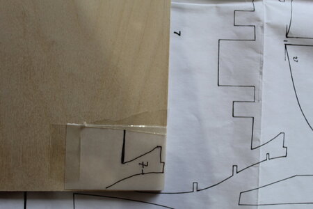
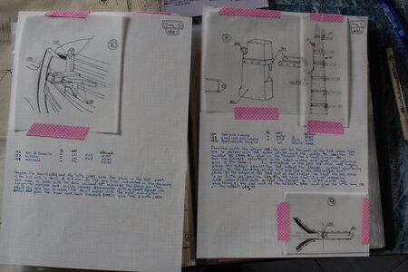
This week, I took diagram 5, and started copying the diagrams and the instructions associated with the drawings, and if needed, for example, if I can not distinguish where the piece goes, I also copy the section from the complete ship where it goes. Like what I did on the second image (diagram 5 instruction #20).
After I finished the ones on the second image, I knew that I did not left my ship in this step. So I started copying diagram 4 (picture 3). I am sure that I did not put the copper, So, tomorrow I will start copying from diagram 3.

I am using washi tape (the pink thing) so I can un-tape the diagrams from the paper, if I need to, or just grab the instruction sheet.
I am also using one side of the paper, per instruction, the reverse side I will use if I need to make further notes when I am working. (like translation to Spanish of English terms that are new)
I am copying word for word, later on I will change things like I did on the Endevour (using the back side of the page to take notes on changes)

I don't plan to copy everything before I start on the hands on, maybe be 3 or 4 diagrams ahead of where I stopped, while I figure out the storage problem. So when days where there is little time to get things out, do ship and put things away, I can advance a figure of the instructions.

PS. I will lower the pixels of the pictures of the camera, I think the pictures are two big.

IMG_7343.JPG

IMG_7346.JPGIMG_7344.JPG
 
Many thanks, Viki for starting your build log! You don't have to worry about the pixels, the bigger photos the better! The forum software does compression without sacrificing quality. We love detailed images... Looking forward to your progress updates. :)
 
I am very happy to see, that you started the building log of your Victory.
And good to see, that you are really planning your way and place of work very well - a bigger model like the Vic will take some time to be finished, so a lot of things have to be well prepared.
I am looking forward to see your working progress
 
Vicki,
Your personal building log, attention to detail is very impressive. Thorough notes and references at your finger tips.
Welcome aboard!
 
During this week, I continued with copying the drawings, but not yet the instructions.
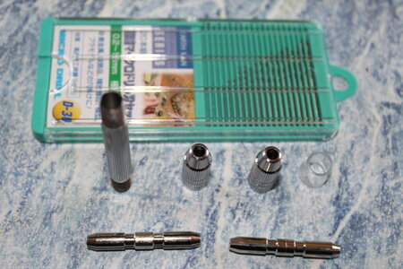
I decided to start an inventory of tools, and I found a drill bit set and a hand drill that I bought back in 2015 in Japan.
I completely forgot about it, but when I saw it I remembered that when buying it I thought "I will use it on my Victory".
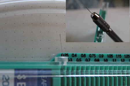
It has drill bits from 0.2mm to 3.2mm. (0.1mm I broke trying to put it on)
Took me a while to learn how to open the box, I am not so good in reading Japanese:
It has a small hole on the edge (second picture) you move the hole around to the size that you need, then the drill goes out. You use it, put it back using the hole. and move the cover so that the hole is not on top of a drill.
IMG_7347.JPG

The drill bit attached is 0.5 mm, the drill bit that shows out of the box is the 0.1mm that I broke.
japanese-drill.JPG
 
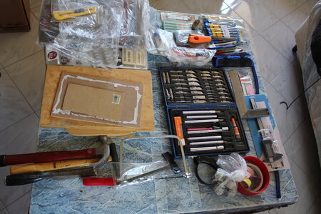
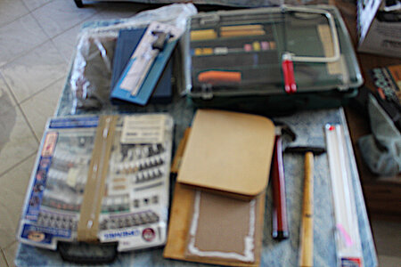
The first picture shows my work table with all the tools I found, the second picture, the toolbox, with the tools and the tools that didn't fit in.
- I have the dremel bits, but the dremel is not working.
- The xacto has plastic caps and 2 are broken.
- Could not find my self healing cutting board.
The things that did not fit on the toolbox, will be kept in the laundry room. If they come out often from there, that means that I need to find a place in the living room to have it at the finger tips.

IMG_7350.JPG

(sorry came out of focus)

tollbox.JPG
 
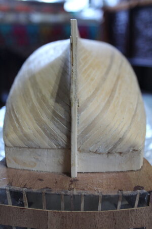
The planking (bow & stern)
My personality shows off: Start something and never finish :-(
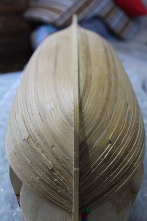
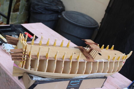
From the images of the bow and stern, you can see:
  • The planking is not finished.
  • There has been some sanding, but yet again it is not finished
  • There are a couple of patches that I had to add because plank went too deep. Needs shaving.
  • The UHU glue is visible. (which reminds me I need to get glue)
  • Symmetry, I think it is not so bad.
IMG_7354.JPGIMG_7355.JPG
 
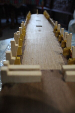
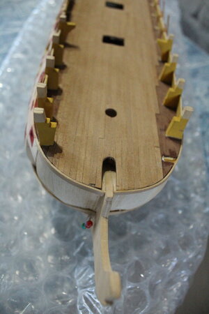
The deck
Again: started, not finished
- In my mind I remember there was a moment when I knew I did not use the correct wood strip
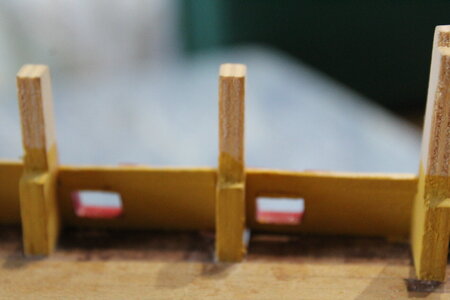
- Frames are pained yellow (I saw the paints, I hope they are still in good shape after around 10 years)
- The window is also painted with red.

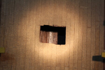
IMG_7356.JPG
I would like to blame the storage, but the frame I remember it was broken way back then.
IMG_7357.JPG
This does not look so bad, (except I need to focus the camera)
IMG_7360.JPG
That hole is also covered with the same wood
IMG_7364.JPG
 
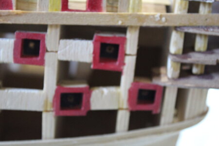
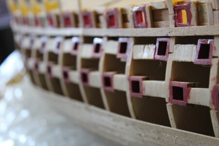
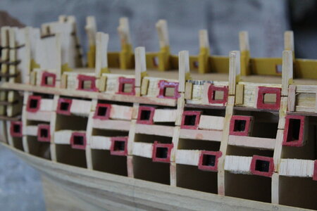
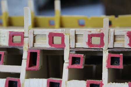
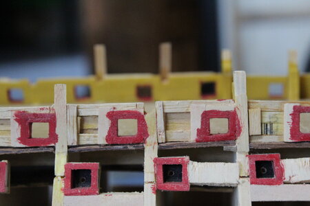
The gun ports

I remember that I didn't like the gun ports that came with the kit. So I made my own.
Now that I see them in detail, they are crooked, they dont look the same size from one another.


IMG_7358.JPG

They don't look aligned, the not so uniform craftwomanship helps also for the bad looking.
IMG_7359.JPG
 
More on gun ports

How I remember doing them:
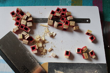
Pivot 10mmx10mm wood, wrapped with wider strips which were glued, remove the pivot, let glue dry, cut. put a cover in the back & drill the hole that will hold the canon head. Then before placing them I painted them.
The wood that helps to hold the gun port in place is balsa wood.

I don't know, I am not convinced.
But now that I see the detail that is what stopped me back then from finishing the planking.
Maybe to start "getting the feel" of the ship, I might do them over. See how they come out, and if they "look" better, remove the other ones and replace them with the new ones. But this time use a plank to at least put them leveled.
Of course first I need to check how "easy" to remove they are.

The ones that are on the deck, I will leave them as they are because I don't want more frames to break. That wood is so fragile.

IMG_7361.JPG
You can notice broken frames. the broken piece needs to be replaced
IMG_7362.JPG
IMG_7363.JPG
 
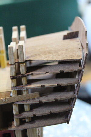
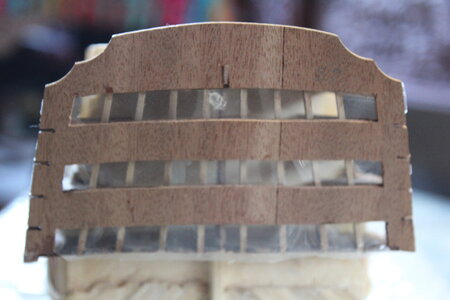
Quarter Galleries

The thing in the back does not look glued. Hope it is not, because if it is, it just looks terrible.
What I do remember is that I was trying to figure out how to make the windows and I used "acetato", don't know the name in English, but is that transparent paper that were used with projectors when doing a presentation.
I need to work out my gluing skills, there is glue everywhere.

So this is the last entry of the log for today. (aka No more pictures)
But I would like your input.

IMG_7365.JPGIMG_7367.JPG
 
Many Thanks for showing us the status - and we see, that there is still a lot of work..... and joy
I will follow with big interest
 
Water line marking with water.
Just for the fun of it.
Material:
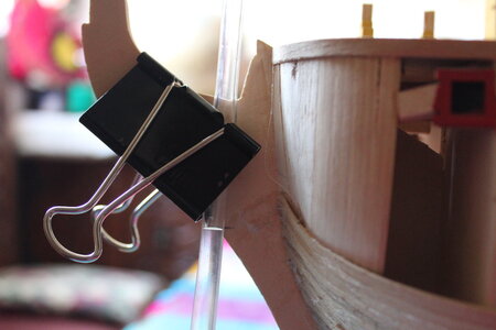
  • 1.5 mts of transparent tube
  • water
  • Pencil
  • Clamp
Step 0) Fill the tube with water
- Make sure there are no bubbles in the water
- Leave 15 cm of air on both ends
Step 1) mark the water line
From the plans mar the water line on the bow and stern.
Camp one end of the tube on the bow or stern making sure that the water is at the lever of the marked water line.

IMG_7380.JPG
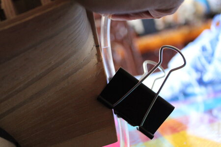
Step 3) Level the ship
By placing the tube on the stern (in my case) move up and down the stern until the mark meets the water of the other end of the tube. You need to be watching the bow side, the ship will be level when the bow and stern match the water marks.


IMG_7381.JPG
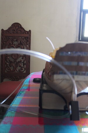
You can see the general situation:
The tube is always bellow the water line except on the ends
IMG_7383.JPG
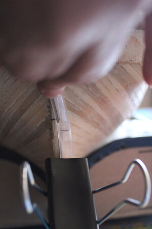
Step 4) Mark other places
Once the ship is leveled, make sure it won't move, grab one end, for example from the stern side, move the tube to the next frame, move it up & dowm, stop when the water on the bow is leveled with the mark, then mark the frame at the same level of the water.
(Sorry forgot to take a final picture) but imagine that this next picture is happening on some other place (say frame #5):
When placing the ending tube from the stern tube on frame #5 three things might happen
1) the water on the bow is bellow the mark on the bow, that means that the tube is too low, move it up a little
2) the water on the bow is above the mark on the bow, that means that the tube is too high, move it down a little
3) the water on the bow is at the mark on the bow, mark the water level at frame #5

In the picture of "the imaginary frame #5", the water on the bow is bellow the mark on the bow, the tube should be moved higher.
IMG_7382.JPG
 
How to destroy a model to have family participation

I though that I was going to be doing this faster than what I am actually doing.
I bought "The Anatomy of Nelson's Ships" and I realized that I have to study a lot.

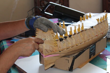
Reading and the water line measure made me decide to take away the gun ports that the ship had. Terrible work, The alignment looked like waves on a thunderstorm. I didn't damage the ship more with that removal.

My older son has now the idea to keep the rudder and wheel working like in the Endeavor and he has the idea to put a small motor to make it move because it is so small and hidden under the poop deck (no finger will fit to move it).
The kit is not made for having a working wheel-tiller-rudder, but, I think it is wonderful that he wants to participate, so I am going to make it happen.
Therefore I also removed the stern wood that it was also glued and will figure out how to do it and kept hours and hours observing to think what to do knowing that
the tiller is on the ceiling of the middle deck and that is glued and it would never be seen. The wheel is also in a very hidden place and if it moves it will be difficult to see the movement.
Some options I've been thinking:
1) move only the rudder
2) have a wheel-tiller-rudder working

Not much consideration I've taken on idea 1, but idea 2 I like more, but only if it is visible.
If there is a motor, then that means that there is electricity somehow, therefore there can be lights, and more movement, like opening/closing some gun ports or moving a sail, or lifting/lowering an anchor, who knows ideas are endless with electricity.
For visibility, an endoscope camera can be used.
For the the location of the tiller:
1) place it on the ceiling of the upper deck.
2) place it on the floor of the upper deck.
3) place it on the ceiling of the middle deck
No matter what, the stern will be visible because adding light, so I have to add floor, plank the wall and very very small decorations.
The problem with (3) is the frames, they are on the way to make it fully functional.
The problem with (1) and (2) is that is not on the correct deck.
The problem with (2) is that is not how it works on the Victory
So I completely discarded option (2)

More time I spent just staring at the ship thinking on option (3).
And it occurred to me, that it is wood, the tiller doesn't have to be that large.
I can drill a hole that goes thru 2/3 frames on the back so that the tiller has enough space to move, make a false deck where the rope for the tiller goes down. The only thing is that I would need to remove the deck that is already installed to be able to work more secure.

More time I spent just staring at the ship. thinking at option (1)
Less wood to drill, I haven't placed the ceiling so I have room to work, the gun ports are open so an endoscope camera fits to see it work, (not at its fullest because its the wrong deck) There is enough room to put the motor, and can be simulated with rope or barrels.

I might go for option (1) model wrong but easier for me, and helps on the family participation.

On the mean time I am working on making the gun ports, and of course the studying.
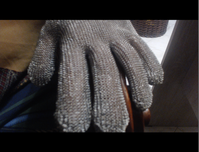
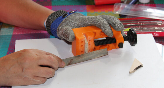
(my other son is also participating by putting band aids to my cuts, and he bought me a metallic glove)


IMG_7385.JPG
glove.png
 
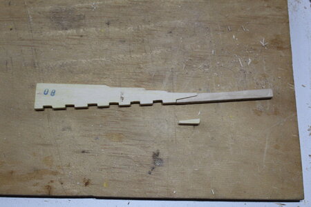
Creating broken pieces of the frames

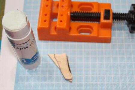
Made a copy of the piece, the floor will not be needed that is not broken, but it helps my imagination of the goal I have
IMG_7386.JPG
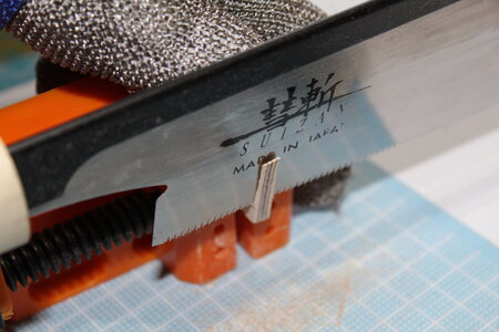
Practicing skills with the saw. and of course the protection is important. I still have 10 fingers :)
IMG_7390.JPG
I used the dremel to make the curves, I changed bits so many times, my family thought I was making a fire because they say that it smelled burned wood all over the house. I didn't smell anything. I need to study dremel bits 101. I ended using files.
IMG_7387.JPG
When one was ready I glued to the wood that will become the second one as they need to be with the same shape
IMG_7388.JPG
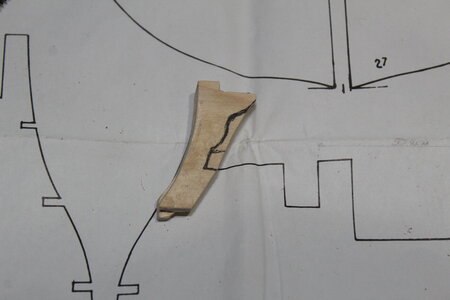
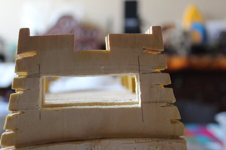
I was thinking that the original design is too wide so I marked it to reduce it a little. That I did because it will only support the gang ways, therefore they will not have much stress as other parts of the deck
IMG_7391.JPG
A whole day to reach to this point. and that is only with frame #7, I still need to finish the idea of reducing it, and do for #6, #8 and #9 frames.
But I am getting more confident on the use of the tools.
 
Cleaning up the ports

Some ports survived the removal
In these picture:

- Above the sanding board some ports that are broken
- the ports on the left that have balsa wood. I removed that wood with the saw.
- On the top right ports without the balsa wood
- and a couple of ports that are sanded and clean.


IMG_7392.JPG
 
Step for the working rudder
I used a drill to make holes at the deck level.
You can see my hand held vacuum cleaner. As at the end when I work inside the house I do it in the dinning table, I clean it often.

IMG_7393.JPG
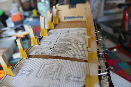
Deck has a the plans of what it is supposed to have, so I don't lose context.
IMG_7394.JPG
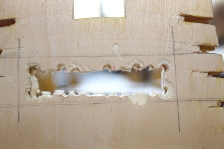
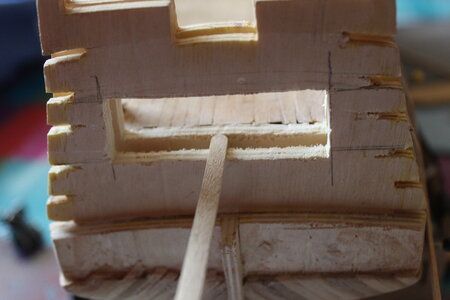
Evolution of the opening for the tiller:
IMG_7395.JPGIMG_7396.JPG

Using a coffee stir to check that the outer frame is a bit lower so that floor can be placed
IMG_7397.JPG
Because the tiller will be placed one deck above of what the real position is, I have to enlarge the rudder.
IMG_7399.JPG
 
Other topics out of context
I applied to go to go to the moon.
My tweet about it
There is aprox an 8 out of one million chance for me to go. which is larger than 0.
Lets see what happens.
If you are curios and click on the tweet link you might read about a dear friend of mine is gone because of the corona.
Please take care.
 
With this post I am opening my build log of the HMS Victory.
On the first picture you can see a cardboard box on the top of the bookshelf, the hull that I started years ago its there waiting to be revived.
I am starting from step 0. Which is to study the plans.

The Endeavor I made, I did it at my dad's house, but now little grandson lives there, too dangerous with a kid, and I could only go on weekends. So this time that is not possible.
I have space restrictions, so there will not be a special room for the shop, so before I unpack the materials, tools and the hull, because I will work on the center table (1mt x 1 mt) of the living room and/or on a table that is outside (not covered), I need to find out how/where I am going to store the tools, how/where I am going to store the material, how/where I am going to handle those large diagrams and where I will put the ship. All that in such a way that I can make progress on the work, and put away everything regardless of where I am working

The solution I found for the large diagrams is to copy them, advantages:
1) Helps on the studying phase
2) Not need spread out a large paper to read the instructions.
3) Have a larger font size so the reading is easier.
4) Build it on my mind while I copy

This week, I took diagram 5, and started copying the diagrams and the instructions associated with the drawings, and if needed, for example, if I can not distinguish where the piece goes, I also copy the section from the complete ship where it goes. Like what I did on the second image (diagram 5 instruction #20).
After I finished the ones on the second image, I knew that I did not left my ship in this step. So I started copying diagram 4 (picture 3). I am sure that I did not put the copper, So, tomorrow I will start copying from diagram 3.

I am using washi tape (the pink thing) so I can un-tape the diagrams from the paper, if I need to, or just grab the instruction sheet.
I am also using one side of the paper, per instruction, the reverse side I will use if I need to make further notes when I am working. (like translation to Spanish of English terms that are new)
I am copying word for word, later on I will change things like I did on the Endevour (using the back side of the page to take notes on changes)

I don't plan to copy everything before I start on the hands on, maybe be 3 or 4 diagrams ahead of where I stopped, while I figure out the storage problem. So when days where there is little time to get things out, do ship and put things away, I can advance a figure of the instructions.

PS. I will lower the pixels of the pictures of the camera, I think the pictures are two big.
Hallo Vicky alias @cvvergara
we wish you all the BEST and a HAPPY BIRTHDAY
Birthday-Cake
 
Back
Top