HMS Victory, Inside out

You should visit more often our forum, not only because your own topic, but also to see the huge number of other interesting talks.
And off course we would be happy to see your progress more often
 
Uwe,
You are completely right. The only excuse I have is that writing English is rather difficult for me. Reading is a bit better, but a lot of words I have to look up.
But I will try to visit more often.
 
Google translate is a good medium to use. And if translation don"t work just use the dutch words. The're always members who will help translate.
 
Google translate is a good medium to use. And if translation don"t work just use the dutch words. The're always members who will help translate.
And the Admins are able to edit your post afterwards and add the english google translation.....
So do not hesitate to post .......
 
I will post a follow-up soon. Someone told me about Deepl.com which also allows you to translate texts. Translates better than google.com.
This is translated by deepl.com
 
Update 13
It has been over a month since my last post. Some people on this forum asked me to post more. This is difficult for me because I have difficulty with English.
Recently I was made aware of the translation program Deepl.com which would translate better than google.com.
That opens the way to translate my Dutch report and post it here. There is a disadvantage or maybe an advantage: it is much more extensive. Would you let me know, through your reactions if this extensive report is appreciated?
If yes then I will handle it from now on.
So time for a sequel.

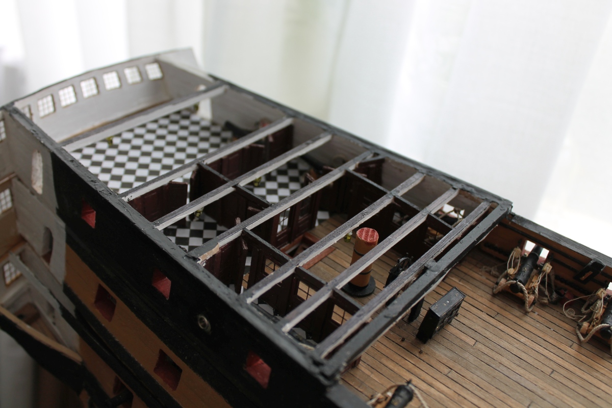
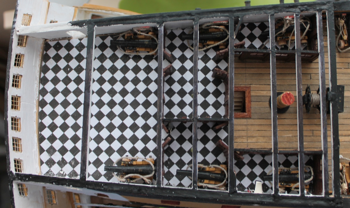
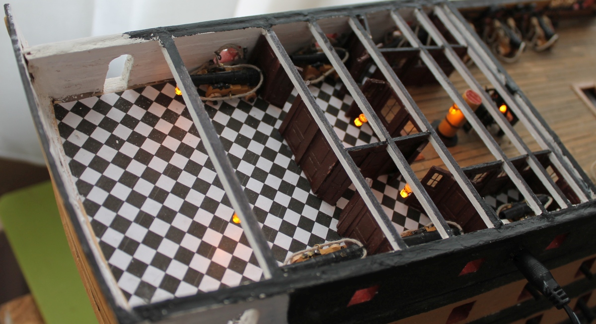
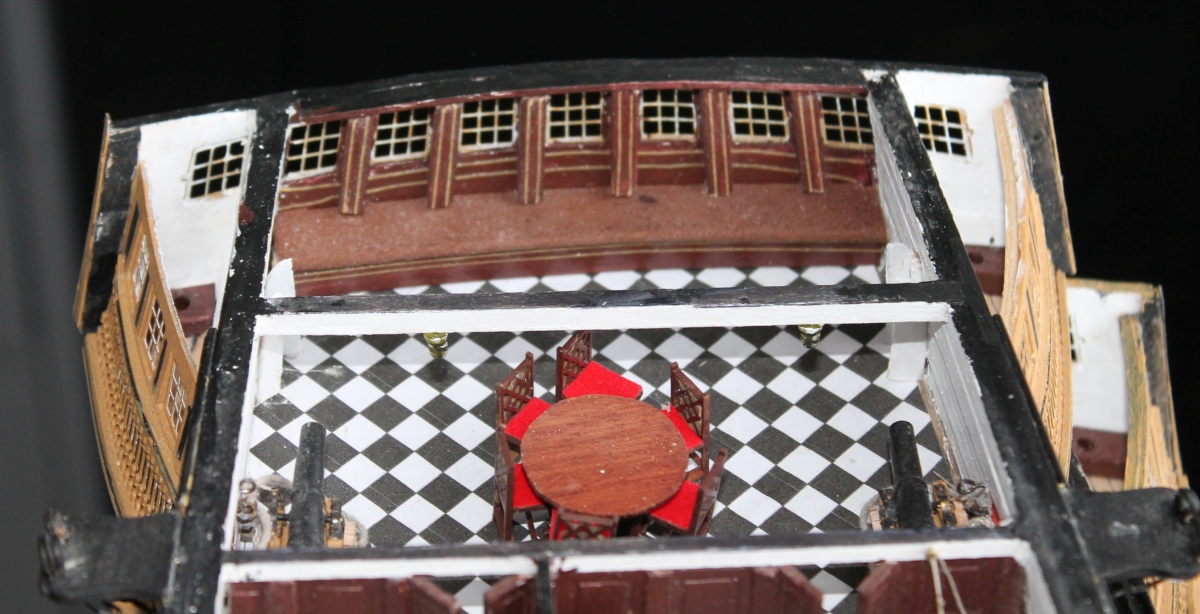
On the aft end of the quarterdeck are the captain's quarters.
I've started working on the separation of the captain's quarters on the quarterdeck. This is a tricky one because there are many dependencies involved here.
1. The location of the partition has many relationships with the rest of the ship.
2. The size of the sections of the partition is determined by the brass window posts from Caldercraft's hardware set.
These two requirements turned out to be conflicting.
I will give you an insight into this.
206-1-Mc-Gowan.jpg
Photo: Overview from McGowan.


206-2-McKay.jpg
Photo: Floor plan from McKay.


206-3-IngangVictory.jpg
Photo: Used to be on the Victory. It is now painted yellow.


206-4-McKay3.jpg
Photo: Floor plan with notes.

The green line indicates the subject. The long red line is the end of the poop deck and the red circles on the bulwark indicate where the partition should touch the bulwark. The red rectangle is the stairway opening to the upperdeck and extends into the admiral's dining room. The bulkhead must therefore run behind it. So the thick red line indicates the absolute length of the bulkhead, determined by the front and the rear.
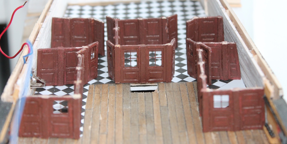
This partition consists of three bulkheads and a door with a pillar on either side of it. See also the photo on the Victory.

On the model this absolute length measured out. Now to determine the dimensions of the bulkheads and door. Made a sketch for this purpose.


206-5-schets.jpgPhoto: Sketch with dimensions in mm.

Below as the partition should be and on top the dimensions of the doors and partitions.
With three bulkheads between the two end pillars I don't get to the necessary length. I need to add another 6 mm. The bulkheads cannot be wider because then the ratio of the windows to the width is not correct. Solved by placing 2 extra pillars of 3 mm between the three bulkheads.
For this I made the sketch below.

206-6-Schets+ramen.jpg
Photo: sketch of partition with two extra pillars between the partitions. On the right the brass windows from the Caldercraft kit. From the photo on the Victory, the windows are taller than wide. The Caldercraft kit mounts them horizontally, so wider than tall. This also suits me better, gives a little more length. The doors in the rear bulkhead open forward on McKay, on the Victory itself backward. I chose the latter.

206-7-PlattegrondOpModel.jpg
Photo: Sketch laid out on model. The bulkheads fit neatly in relation to the "surroundings" both front and rear.

And now we can start making the bulkheads. (11 pieces)
I have already shown this once so now just a quick look:]

206-8-SchottenInAanbouw.jpg
Photo: Bulkheads in various stages of completion.


206-9-SchotVoorSchilderbeurt.jpg
Photo: Before the paint job.

206-A-schotjes.jpg
Photo: All the parts for the front bulkhead.

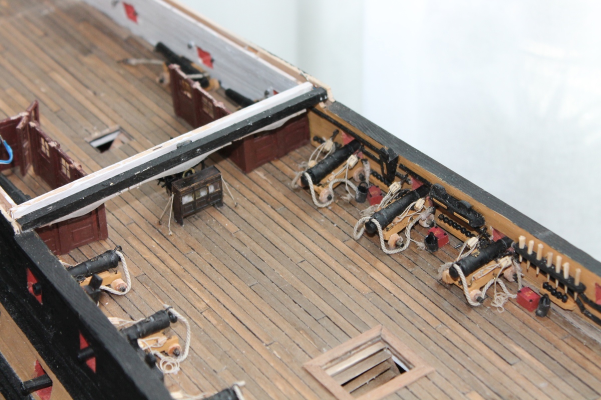
And now a quick look at the middle bulkhead.
So yeah, that's a bit late.
What's the problem?


206-B-GrotePlattegrond.jpgPhoto: Floor plan on the model to illustrate the problem.

The green line shows the bulkheads that are already finished. (See previous photo). The red lines show the bulkheads I want to make now. But ........ the left one comes out center for a gun port and the right one on the edge of it. (Gates are not exactly opposite each other) So that is not possible. But the bulkhead can't go forward because of the green line and the stairwell, and it can't go backward past the gate because then there's no room for the cannon that goes alongside it. And even if it could be there it would be in a space without a gate.
I had to resort to a very undesirable solution of placing the side bulkheads at an angle along the yellow line. That has the least consequences. But I am absolutely not happy with it.
I hear you say: How can it not be right? Aligning everything exactly to a mm across six (loose !!!) decks is not doable. And 1 mm difference here results in 2 mm difference there and before you know it you have a difference of half a cm. It is no different.

To be continued.
Translated with www.DeepL.com/Translator (free version)


The following three pictures have an own will. They don't want to be removed.
206-McKay2.jpg

206-McKay2-test.jpg

206-McKay2-test2.jpg
 
Last edited:
I am personally very happy with the more information you are able to make
Building logs can never be too long or too detailed - and the new software is doing a very good translation work!
 
Update 14
All the bulkheads are finished and painted. Here they are still loose on the deck, as first the cannons need to be in place.
The floor covering is also still loose in there and the connection for the LEDs is visible on the left.

207-1-Schotten-klaar.jpg

Photo: Captain's quarters partitions loosely placed with doors in open position. The rear center bulkhead is in the wrong position, doors should open forward.

The 6 cannons on the quarterdeck are placed and also the binnacle (Compass house) with lights and the steering wheel.
Also the first space on port side is made and a canon tied in alongside.

208-1-quarterdeck.jpg

Photo: Cannons placed on quarterdeck. Also note the rolled up sailcloth under the beam above the compass housing. With this the space of the steering wheel could be shielded for bad weather.
Visibility was almost non-existent anyway e.g. through the blind. Steering instructions were given by the "lookout".

Recently I have placed the captains quarters. Here are some pictures:

209-1-Schuin.jpg

Photo: Inclined from the front

209-2-Boven.jpg

Photo: Straight from the top.

209-3-Verlicht.jpg

Photo: With lighting.

Now to dress up the various rooms with some furniture.
Also, in the admirals and captains day rooms, I placed a bench against the mirror wall.

229-2-Kapiteinskamerbank.jpg

Photo: Back of the captains day room with a leather couch over the entire width.

To be continued.

Translated with www.DeepL.com/Translator (free version)
You are producing very well crafted interior fittings and so well placed. Great lighting for your excellent photos. First Place Metal Rich (PT-2)
 
Hi all,
A few years ago I build the HMS Victory with the DeAgostino kit. And then I found the book of John McKay "The 100 gun-gun ship Victory". This book shows all the details necessary to build the Victory from scratch.
After the DeAgostini model was finished, and visited the Victory in Portsmouth, I decided to build the Victory from scratch, included all the internal details.
Of that build I made a report on the dutch forum: https://www.modelbouwforum.nl/threads/hms-victory-binnenste-buiten.212385/
It is in Dutch, but I will post here the most essential things, so you can follow it also.
Hallo Jan alias @janzwart
we wish you all the BEST and a HAPPY BIRTHDAY
Birthday-Cake
 
Update 15
You are still owed an update from me.
One important part of the Victory that I haven't shown you yet is the transom. When building it, I also saved that until last because making it is only possible when all the decks are available. So the decks I have made so far without a back wall.

15-sos-01.jpg

This has been the back for a long time.

The ornaments of the transom are from Caldercraft. This is the reason I also chose the 1:84 scale, so those ornaments will fit.
I built the transom from the bottom up, so first the back wall of the wardroom.

15-sos-02.jpg


15-sos-03.jpg

Outside and
15-sos-04.jpg

inside. I didn't put plastic film on the windows. That wouldn't fix it up.

Then I put all the ornaments on a jig to determine the distances between them.
15-sos-05.jpg


In photos of the Victory, I determined the separation of the decks on the transom.
15-sos-06.jpg


And then divided the mold into decks that way and temporarily fixed it on the model.
15-sos-07.jpg


This way I was able to determine the correct location of the ornaments, taking into account the deck separation.
After some finishing, the transom looked like this:
15-sos-08.jpg


Unfortunately, the width was not correct.
15-sos-09.jpg


Here you see on the left the original, in the middle my model and on the right between the red lines what has to come off.
You can see that I succeeded quite well:
15-sos-10.jpg


Left the Victory and right what I made of it.
Now for the galleries, first apply the interior. That will look like this:
15-sos-11.jpg


And the bottom one seen from above.
15-sos-12.jpg


To make the outside fit I used molds again.
15-sos-13.jpg


And that led to the following result:
15-sos-14.jpg


And that all decks can still be separated shows this picture.
The last deck to be made is the poop deck. That's also where the three lanterns are. And I wanted to have lighting in there as well.
I replaced the supports of the lanterns (from Caldercraft) with brass tubes of 1 mm diameter and ran the wiring through them.
15-sos-15.jpg


The three LEDs are in series with a resistor and are powered by 6V. Here they are sitting on the back of the inside of the transom and the lighting test has been passed.
15-sos-16.jpg


And after finishing the lanterns it became this.
15-sos-17.jpg


For on the poop deck I made an flag box out of thick paper, of course with the right number of compartments.
15-sos-18.jpg


Parts of the flag box.
And after placing it on the deck along with some other accessories, the poopdeck looks like this:

15-sos-19.jpg
 
In this last update I will show you again all the decks:
The hold:
15-sos-20.jpg


Orlopdeck:
15-sos-21.jpg


Lower gundeck:
15-sos-22.jpg


Middle gundeck:
15-sos-23.jpg


Upper gundeck:
15-sos-24.jpg


Fore, quarter and poopdeck.
15-sos-25.jpg


For demonstration purposes, I made a box with drawers that fit one deck each. This way I can easily and quickly show all decks separately.
15-sos-26.jpg


Nice detail: The nameplate on the stand is made from the copper plates removed from the original Victory. Purchased from the Victory's gift shop, with certificate of authenticity.
15-sos-27.jpg


End of this report.
 
Fantastic build, in september I will see her with my own eyes. This only is worth visiting the gathering of shipbuilders and their project.
 
Hi all,
A few years ago I build the HMS Victory with the DeAgostino kit. And then I found the book of John McKay "The 100 gun-gun ship Victory". This book shows all the details necessary to build the Victory from scratch.
After the DeAgostini model was finished, and visited the Victory in Portsmouth, I decided to build the Victory from scratch, included all the internal details.
Of that build I made a report on the dutch forum: https://www.modelbouwforum.nl/threads/hms-victory-binnenste-buiten.212385/
It is in Dutch, but I will post here the most essential things, so you can follow it also.
Thanks. Unfortunately, I cannot read Dutch but I can see photos amd I am sure they will also be helpful.
 
WOW!!!.. In what scale are you building this model. Do you have any photos of the pumps? I am especially in need of dimensions for them so that I can construct them for my cross-section model. The Corel model totally left them out/off. Any suggestions will be greatly appreciated.
 
Back
Top