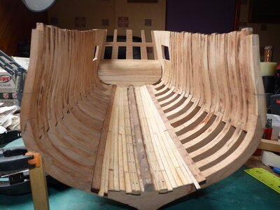
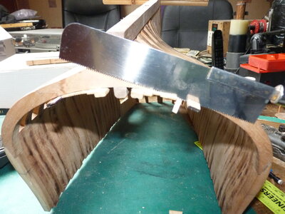
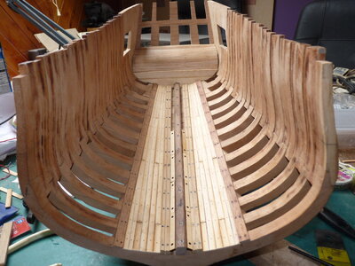
HMY Fubbs
This build will be a step into a mostly unknown area, a plank on frame construction. The fact that I’m building it at all is thanks to Winston and Mike Shanks and it’s the 10th (and last) of a limited production run.
My sincere thanks to both for including me in this project.
The project started here:
PICT_F_0101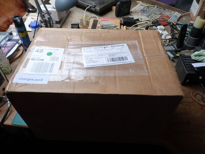
Even before receiving the kit I was aware that the documentation was in a different league to any of my previous kits so let’s start with that.
There were two large boxes in the parcel pictured above (in about an acre of bubble wrap) and I knew that there was a USB stick with instructions in there somewhere. Everything other than the frame pieces was labelled so it was relatively easy to find. A file titled ‘Assembly instructions’ seemed to be a reasonable place to start and opened with the following:
Introduction – Historical
His Majesty Yacht (HMY) Fubbs was laid down at Greenwich shipyards by Phineas Pett in 1682. By Royal Navy standards yachts would be the size of a typical harbor dispatch vessel or lightly armed gunboat. HMY Fubbs sported a keel length of only 63’ with at a specified 148 tons fully load ed. With a 21’ breadth and only 9’6” depth in hold these small ships carried a crew of up to 30 and could be armed with 8 – 12 3 pounders. Royal Yacht duties primarily consisted of tending to the affairs of the royal household. Charles II must have enjoyed yacht class vessels as he had 23 of them during his reign – more than any other English king. HMY Fubbs was the most lavish of his fleet of Royal Yachts. Visually, the hull of a Royal Yacht has the look of a 6th rate but is more akin to a ketch-rigged sloop. As such, she has a mizzen mast that passes through the small great cabin and no true orlop deck at all. As will be shown later, the stern ports are too close to the waterline and are not actually accessible from inside the ship. What look like stern quarter galleries are more like quarter badges. Most contemporary modelers and many artists tend to imagine HMY Fubbs as a larger ship than it really is due to the illusion created by the artistic style of the ship. Charles II employed well known Baroque period artists Van de Veldes younger and senior. Their artwork had a direct influence on the highly decorated HMY Fubbs. HMY Fubbs was named after the mistress of Charles II, the Duchess of Portsmouth, Louise de Keroualle. “Fubbs” was the nickname for Charles II mistress with the meaning of a chubby contemptuous child. HMY Fubbs remained in service for more than 80 years before being broken up in 1781. During that time, it went through 2 refits. One in 1701 and again in 1724. During the 1724 refit, most of her carvings were salvaged and replaced by painted frieze work. There is sufficient historical evidence on Royal Yachts to know they were lightly framed compared to other Royal Navy ships. It was noted that HMY Fubbs would require futtock riders to support the light frame timbers. While the specific duties of HMY Fubbs may not be known it is reasonable to expect the vessel was probably used for intimate entertainment purposes and fine dining. I would expect being a crew member on this ship would be rather plush duty.
One thing I wanted to check was how the frame templates would print. I assumed the drawings would have been printed on ‘Letter’ sized paper whereas I would be printing them on A4 paper.
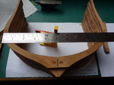
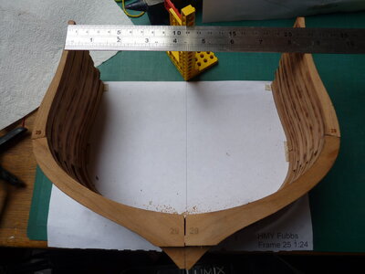
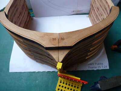
One of the boxes contained a bag of pieces for frame 25, these were CNC cut so should match the printed template.
The printer decided the print was larger than the print area and defaulted to ‘Fit’. I changed it to ‘Actual size’ and, just to play safe, changed the paper orientation from ‘Auto’ to ‘Landscape’. That actually changed settings so I suspect ‘Auto’ might have printed on 2 portrait pages.
So, I crossed my fingers, selected current page, and clicked print. I’d used an old sheet of paper, thinking that A4 was wider than Letter (it’s about 1/4” narrower). The print looked reasonable, and the parts all lined up.
PICT_F_0102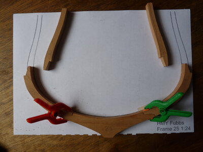
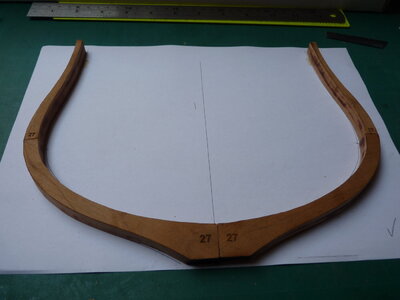
The tops of the frames aren’t actually shown but everything does line up and the next picture shows frame 25 held with double sided sticky tape and glued together
PICT_F_0103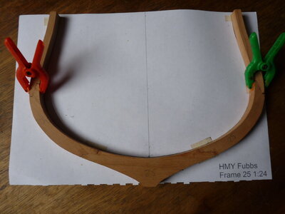
Time to see what’s involved with the first laser cut frame.
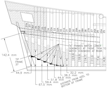
I printed the template for frame 25A and found it was clipped both top and bottom, but still showed the relative positions of the pieces.
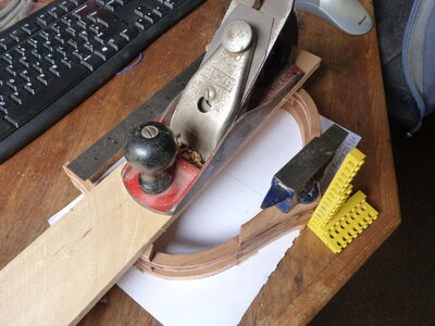
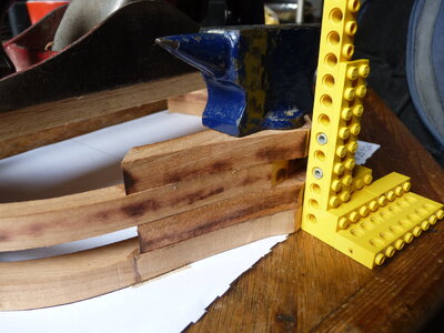
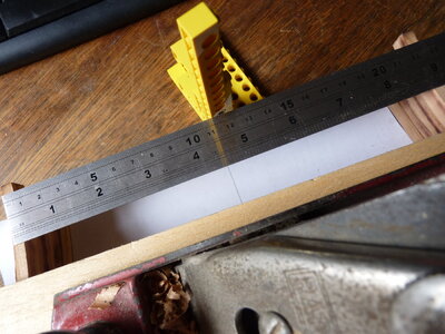
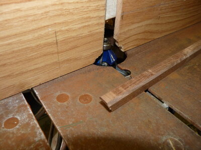
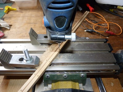
At this point I needed to bevel the pieces of frame 25A and remove the char from the end grain. Mike recommends a spindle sander for this job. I don’t have a spindle sander, but I do have this:
PICT_F_0104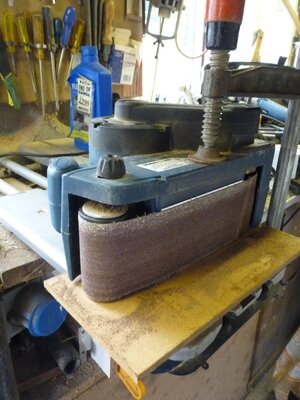
At this point, this is what I found, the port side upper frame piece 25A:
PICT_F_0105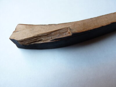
Despite a search, I didn’t find the missing piece in the box. Neither did I find a matching piece of timber in all my stock. What I did find in the box was a bag containing 8 pieces marked ‘Dead wood’. The question was whether I could use one of those for a repair? A skim through the instructions, build logs and pictures showed me I needed 5. If I do need all 8, I’ll cross that bridge when I come to it!
I cut out a nice square rebate in the frame piece, cleaned up one of the deadwood pieces and glued it in the rebate.
Here’s how it looks after cutting off the excess and a bit of sanding.
PICT_F_0106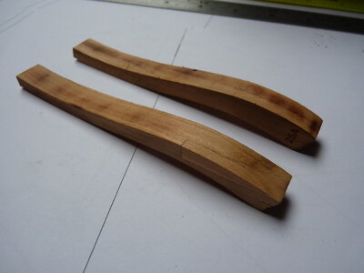
The side won’t be visible when it’s fitted.
This build will be a step into a mostly unknown area, a plank on frame construction. The fact that I’m building it at all is thanks to Winston and Mike Shanks and it’s the 10th (and last) of a limited production run.
My sincere thanks to both for including me in this project.
The project started here:
PICT_F_0101

Even before receiving the kit I was aware that the documentation was in a different league to any of my previous kits so let’s start with that.
There were two large boxes in the parcel pictured above (in about an acre of bubble wrap) and I knew that there was a USB stick with instructions in there somewhere. Everything other than the frame pieces was labelled so it was relatively easy to find. A file titled ‘Assembly instructions’ seemed to be a reasonable place to start and opened with the following:
Introduction – Historical
His Majesty Yacht (HMY) Fubbs was laid down at Greenwich shipyards by Phineas Pett in 1682. By Royal Navy standards yachts would be the size of a typical harbor dispatch vessel or lightly armed gunboat. HMY Fubbs sported a keel length of only 63’ with at a specified 148 tons fully load ed. With a 21’ breadth and only 9’6” depth in hold these small ships carried a crew of up to 30 and could be armed with 8 – 12 3 pounders. Royal Yacht duties primarily consisted of tending to the affairs of the royal household. Charles II must have enjoyed yacht class vessels as he had 23 of them during his reign – more than any other English king. HMY Fubbs was the most lavish of his fleet of Royal Yachts. Visually, the hull of a Royal Yacht has the look of a 6th rate but is more akin to a ketch-rigged sloop. As such, she has a mizzen mast that passes through the small great cabin and no true orlop deck at all. As will be shown later, the stern ports are too close to the waterline and are not actually accessible from inside the ship. What look like stern quarter galleries are more like quarter badges. Most contemporary modelers and many artists tend to imagine HMY Fubbs as a larger ship than it really is due to the illusion created by the artistic style of the ship. Charles II employed well known Baroque period artists Van de Veldes younger and senior. Their artwork had a direct influence on the highly decorated HMY Fubbs. HMY Fubbs was named after the mistress of Charles II, the Duchess of Portsmouth, Louise de Keroualle. “Fubbs” was the nickname for Charles II mistress with the meaning of a chubby contemptuous child. HMY Fubbs remained in service for more than 80 years before being broken up in 1781. During that time, it went through 2 refits. One in 1701 and again in 1724. During the 1724 refit, most of her carvings were salvaged and replaced by painted frieze work. There is sufficient historical evidence on Royal Yachts to know they were lightly framed compared to other Royal Navy ships. It was noted that HMY Fubbs would require futtock riders to support the light frame timbers. While the specific duties of HMY Fubbs may not be known it is reasonable to expect the vessel was probably used for intimate entertainment purposes and fine dining. I would expect being a crew member on this ship would be rather plush duty.
One thing I wanted to check was how the frame templates would print. I assumed the drawings would have been printed on ‘Letter’ sized paper whereas I would be printing them on A4 paper.
One of the boxes contained a bag of pieces for frame 25, these were CNC cut so should match the printed template.
The printer decided the print was larger than the print area and defaulted to ‘Fit’. I changed it to ‘Actual size’ and, just to play safe, changed the paper orientation from ‘Auto’ to ‘Landscape’. That actually changed settings so I suspect ‘Auto’ might have printed on 2 portrait pages.
So, I crossed my fingers, selected current page, and clicked print. I’d used an old sheet of paper, thinking that A4 was wider than Letter (it’s about 1/4” narrower). The print looked reasonable, and the parts all lined up.
PICT_F_0102

The tops of the frames aren’t actually shown but everything does line up and the next picture shows frame 25 held with double sided sticky tape and glued together
PICT_F_0103

Time to see what’s involved with the first laser cut frame.
I printed the template for frame 25A and found it was clipped both top and bottom, but still showed the relative positions of the pieces.
At this point I needed to bevel the pieces of frame 25A and remove the char from the end grain. Mike recommends a spindle sander for this job. I don’t have a spindle sander, but I do have this:
PICT_F_0104

At this point, this is what I found, the port side upper frame piece 25A:
PICT_F_0105

Despite a search, I didn’t find the missing piece in the box. Neither did I find a matching piece of timber in all my stock. What I did find in the box was a bag containing 8 pieces marked ‘Dead wood’. The question was whether I could use one of those for a repair? A skim through the instructions, build logs and pictures showed me I needed 5. If I do need all 8, I’ll cross that bridge when I come to it!
I cut out a nice square rebate in the frame piece, cleaned up one of the deadwood pieces and glued it in the rebate.
Here’s how it looks after cutting off the excess and a bit of sanding.
PICT_F_0106

The side won’t be visible when it’s fitted.
Last edited:


