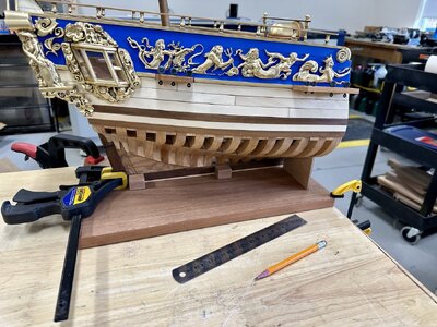
Great work so far, Arthur! Keep going!
You are using an out of date browser. It may not display this or other websites correctly.
You should upgrade or use an alternative browser.
You should upgrade or use an alternative browser.
It's time the log caught up with the actual state of play, starting with the parquet floor.
This first picture had me puzzled for a while, I definitely didn't have any ebony strips!
I'd taken the photo with flash and those were shadows, but I'm not sure how it got turned round. the second picture is the opposite way round.
PICT_F_1301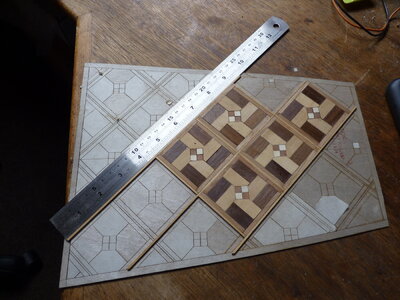
I may have missed a trick here.
Mike said that he could assemble each square with very little work on the individual pieces. I had to trim the pieces to get them to fit within the template. If I'd just accepted that each square was slightly larger than the template, the overall result would probably have been the same.
PICT_F_1302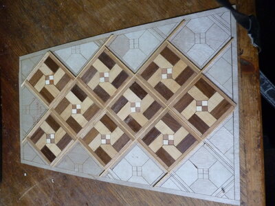
I agree with Mike that fitting the border pieces was the biggest challenge. Trimming the edges of the pattern to meet the border planks was, to say the least, difficult. I'd suggest dry fitting the border plank across an edge border square before fitting the individual pieces.
To finally fit the planks, a lead acid battery held the border planks in place while the glue dried:
PICT_F_1303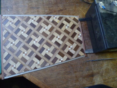
The next step was a welcome change, rather than several days, this took a matter of minutes. (Not counting the time it took to clean up the deck beams.)
PICT_F_1304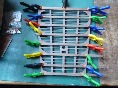
And here's the floor after some work with a couple of cabinet scrapers:
PICT_F_1305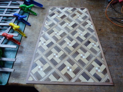
The next step was the critical one, getting the position of the deck clamp correct. The most difficult part was to get the hull level port to starboard and keeping it there whilst I measured it.
Hopefully, it's in the right place:
PICT_F_1306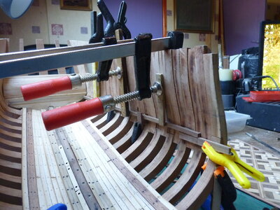
And here's the other side:
PICT_F_1307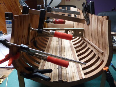
The level says they're either both right or they're both wrong.
I have left myself with a slight problem though; I should have trimmed them to length!
This first picture had me puzzled for a while, I definitely didn't have any ebony strips!
I'd taken the photo with flash and those were shadows, but I'm not sure how it got turned round. the second picture is the opposite way round.
PICT_F_1301

I may have missed a trick here.
Mike said that he could assemble each square with very little work on the individual pieces. I had to trim the pieces to get them to fit within the template. If I'd just accepted that each square was slightly larger than the template, the overall result would probably have been the same.
PICT_F_1302

I agree with Mike that fitting the border pieces was the biggest challenge. Trimming the edges of the pattern to meet the border planks was, to say the least, difficult. I'd suggest dry fitting the border plank across an edge border square before fitting the individual pieces.
To finally fit the planks, a lead acid battery held the border planks in place while the glue dried:
PICT_F_1303

The next step was a welcome change, rather than several days, this took a matter of minutes. (Not counting the time it took to clean up the deck beams.)
PICT_F_1304

And here's the floor after some work with a couple of cabinet scrapers:
PICT_F_1305

The next step was the critical one, getting the position of the deck clamp correct. The most difficult part was to get the hull level port to starboard and keeping it there whilst I measured it.
Hopefully, it's in the right place:
PICT_F_1306

And here's the other side:
PICT_F_1307

The level says they're either both right or they're both wrong.
I have left myself with a slight problem though; I should have trimmed them to length!
Last edited:
The next step seemed to be creating and positioning the quarter deck. After I’d gathered the parts, there was a slight change of plan, and I opted to also assemble the frames for the poop deck.
Mike claims that the parts will fit the pre-cut notches. Sorry Mike, not even close! However, sanding the parts to fit the notches (rather than vice-versa) worked well.
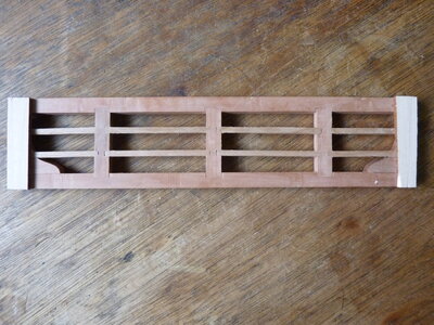
This is the quarter deck:
PICT_F_1401
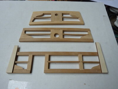
And these are for the poop deck:
PICT_F_1402
The next step, working out where these actually fit, is critical to the relative positions of several components.
The distances of the quarter & poop deck clamps from the keel are given but I opted to position them relative to the great cabin deck clamps which were much easier to measure. That allowed me to test fit the entryway bulkhead which sits on the quarter deck planking.
PICT_F_1403
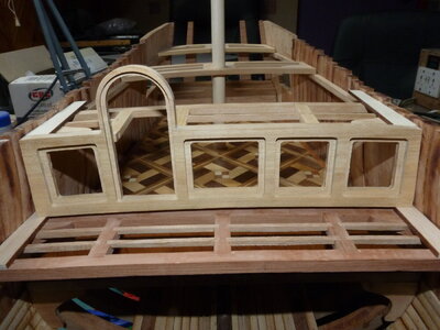
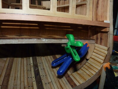
The picture also shows the partial ceiling planking and the knees supporting the great cabin floor but here’s a close up of how the knees were trimmed and fitted:
PICT_F_1404
The following picture shows a dry fit of the panelling and steps inside the great cabin:
PICT_F_1405
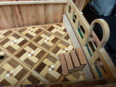
I’m not going to admit to how many times I put those steps together, decided they weren’t right, took them apart, and tried again!
Mike claims that the parts will fit the pre-cut notches. Sorry Mike, not even close! However, sanding the parts to fit the notches (rather than vice-versa) worked well.
This is the quarter deck:
PICT_F_1401

And these are for the poop deck:
PICT_F_1402

The next step, working out where these actually fit, is critical to the relative positions of several components.
The distances of the quarter & poop deck clamps from the keel are given but I opted to position them relative to the great cabin deck clamps which were much easier to measure. That allowed me to test fit the entryway bulkhead which sits on the quarter deck planking.
PICT_F_1403

The picture also shows the partial ceiling planking and the knees supporting the great cabin floor but here’s a close up of how the knees were trimmed and fitted:
PICT_F_1404

The following picture shows a dry fit of the panelling and steps inside the great cabin:
PICT_F_1405

I’m not going to admit to how many times I put those steps together, decided they weren’t right, took them apart, and tried again!
Last edited:
Arthur, Your attention to detail is spot on! I think the steps look great! Magic Mike
For some time, I’ve been expecting to have problems making the rudder and tiller actually work. Now that I had the section of poop deck on which the tiller is mounted, it was obvious that this wasn’t going to line up with the gudgeons and pintles on the rudder. That seemed to be a good excuse for a change of task and see about fitting the rudder.
The rudder is actually made up of five separate pieces, but I only needed the forward (largest) piece to work on at this time. I did, however, clean up and test fit the pieces together.
To allow the rudder to pivot, it needs a 45 degree bevel on each side, so it was another job for the router table:
PICT_F_1501
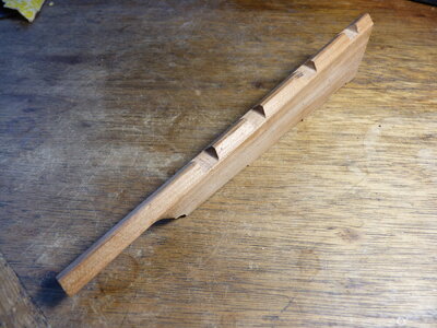
I have since learned that there could be matching 10 degree bevels on the sternpost to allow the rudder a greater range of movement.
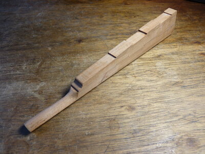
Also, to allow the rudder to turn where it passes through the counter, it needs either a very large hole or a reshaped rudder shaft. I opted for the latter:
PICT_F_1502
I now needed four pairs of gudgeons and pintles. These fit within the rebates in the rudder. The space available should be measured part way into the rebate and that distance is equal to the diameter of the gudgeons:
PICT_F_1503
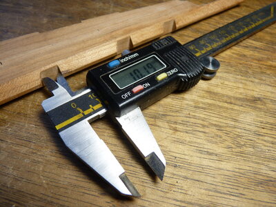
I have a selection of brass rods and tubes, but the rods were too small for the 1:24 scale. I did have some brass tubing of a suitable size, 2.86mm OD – and then I realised I did have some thicker brass rod – the 2.0mm diameter length Mike had included in the kit for lantern supports. It was a perfect fit in the tubing!
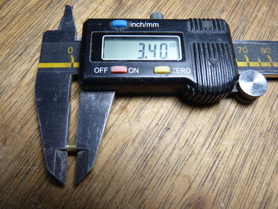
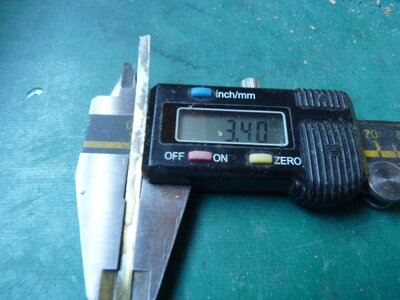
The space in the rebates is shared into three parts, The height of the pintle (excluding the pin), the height of the gudgeon, a space equal to the height of the gudgeon to allow for its removal. In practice, that’s three equal parts of 3.4mm.
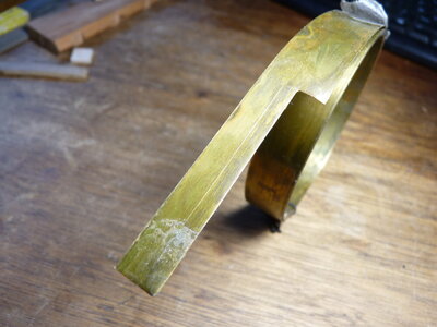
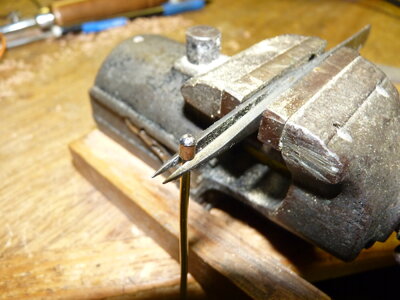
So, here’s how to make a gudgeon:
PICT_F_1504
PICT_F_1505
PICT_F_1506
PICT_F_1507
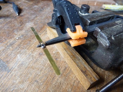
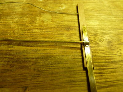
Slightly different technique to make a pintle:
PICT_F_1508
In the next picture there’s a weight, out of shot, resting on the brass wire to hold it down:
PICT_F_1509
PICT_F_1510
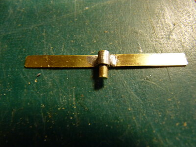
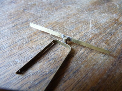
They do fit together – but the other way up!
PICT_F_1511
Back to the rudder itself, the first four pieces were glued together. The bottom corners of the rebates were squared up and the fit of the various sections was most impressive.
PICT_F_1512
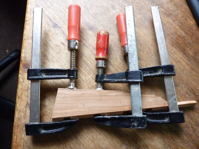
Here’s how it looks with the pintles temporarily fitted:
PICT_F_1513
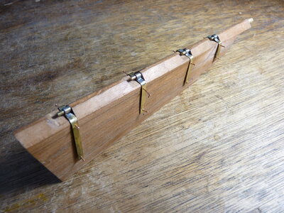
It’s since had piece number five glued on the bottom and has been tapered:
PICT_F_1514
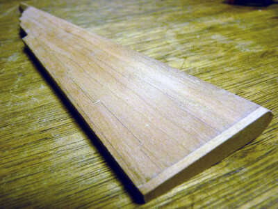
And finally, yes, it fits:
PICT_F_1515
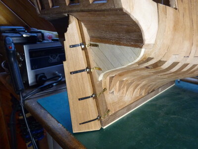
The rudder is actually made up of five separate pieces, but I only needed the forward (largest) piece to work on at this time. I did, however, clean up and test fit the pieces together.
To allow the rudder to pivot, it needs a 45 degree bevel on each side, so it was another job for the router table:
PICT_F_1501

I have since learned that there could be matching 10 degree bevels on the sternpost to allow the rudder a greater range of movement.
Also, to allow the rudder to turn where it passes through the counter, it needs either a very large hole or a reshaped rudder shaft. I opted for the latter:
PICT_F_1502

I now needed four pairs of gudgeons and pintles. These fit within the rebates in the rudder. The space available should be measured part way into the rebate and that distance is equal to the diameter of the gudgeons:
PICT_F_1503

I have a selection of brass rods and tubes, but the rods were too small for the 1:24 scale. I did have some brass tubing of a suitable size, 2.86mm OD – and then I realised I did have some thicker brass rod – the 2.0mm diameter length Mike had included in the kit for lantern supports. It was a perfect fit in the tubing!
The space in the rebates is shared into three parts, The height of the pintle (excluding the pin), the height of the gudgeon, a space equal to the height of the gudgeon to allow for its removal. In practice, that’s three equal parts of 3.4mm.
So, here’s how to make a gudgeon:
PICT_F_1504

PICT_F_1505

PICT_F_1506

PICT_F_1507

Slightly different technique to make a pintle:
PICT_F_1508

In the next picture there’s a weight, out of shot, resting on the brass wire to hold it down:
PICT_F_1509

PICT_F_1510

They do fit together – but the other way up!
PICT_F_1511

Back to the rudder itself, the first four pieces were glued together. The bottom corners of the rebates were squared up and the fit of the various sections was most impressive.
PICT_F_1512

Here’s how it looks with the pintles temporarily fitted:
PICT_F_1513

It’s since had piece number five glued on the bottom and has been tapered:
PICT_F_1514

And finally, yes, it fits:
PICT_F_1515

Arthur, the rudder looks great! Magic Mike
Thanks Mike - and all you who posted 'Likes'.
- Joined
- Apr 26, 2021
- Messages
- 22
- Points
- 58

Looks really great stuff - I am at about the same stage on a scratch build of the Fubbs from Romero’s practice m so following with great interest.
Once more, it's about time I updated this log. However, there's nothing exciting to report!
First on the list was the settee/sofa/couch in the grand cabin, the built in one not the free standing resin one. I don't think any of those names are the right word for it, if it was in a house it would be called a window seat.
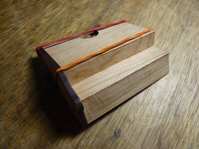
After the problems I had assembling the steps, I decided to assemble the centre pieces first, followed by the side panels.
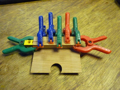
Another job for the Lego:
PICT_F_1601
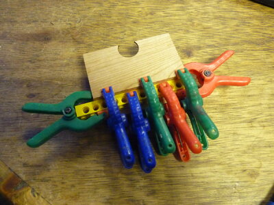
PICT_F_1602
So far so good. This is the first side panel:
PICT_F_1603
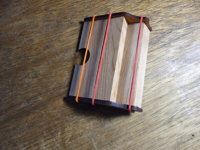
And here’s the final assembly.
I think the char looks OK, so I’m not going to remove it:
PICT_F_1604
There’s still some work to do before I can glue the grand cabin floor in place, so that was next on the list.
There were three separate jobs, fitting the mast step, fitting the limberboard covers and fitting the support pillars, but I don’t appear to have taken photos of the individual stages.
I’ll start with the mast step. This straddles the keelson and its position fore and aft sets the rake of the mizzen mast. Positioning it too far forward will get in the way of the aft-most pillar, so just back a bit from the pillar it was going to be.
That wasn’t the end of the job though, rather than straddling the keelson it was resting on it. Cutting away the bottom centre of the mast step solved that problem.
PICT_F_1605
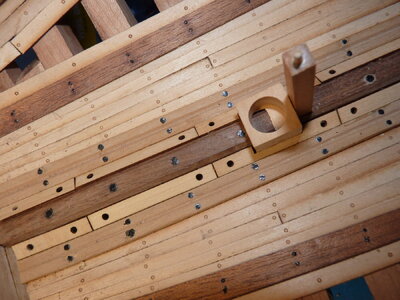
The above picture also shows the remaining limberboard covers cut and fitted.
Fitting the pillars wasn’t too much of a challenge, the same can’t be said about cutting them to the correct lengths!
The foremost one was easy, trying to measure the others with a pair of inside callipers was anything but!
At this point, each of them had a short piece of dowel at the bottom and I could easily see where the foremost pillar fitted in the keelson, so I fitted a dowel in the top of the foremost pillar. The fore and aft spacing of the pillars could be measured on the under side of the deck, so that gave the positions of the other pillars in the keelson.
I finally cut the other pillars over length, rested the great cabin floor on them and checked how much it rocked above the deck clamps. I then trimmed a bit off them and tried again.
When the deck finally sat on the pillars and the clamps, I fitted dowels in the tops of the aft pillars. Although everything now fitted, it took some time to line all the dowels up with their holes, so I glued all the dowels into the pillars and glued the pillars into the keelson.
PICT_F_1606
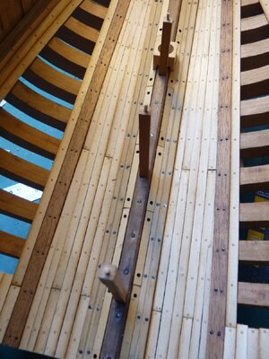
PICT_F_1607
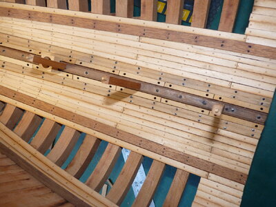
The deck/great cabin floor can now be removed and replaced easily.
First on the list was the settee/sofa/couch in the grand cabin, the built in one not the free standing resin one. I don't think any of those names are the right word for it, if it was in a house it would be called a window seat.
After the problems I had assembling the steps, I decided to assemble the centre pieces first, followed by the side panels.
Another job for the Lego:
PICT_F_1601

PICT_F_1602

So far so good. This is the first side panel:
PICT_F_1603

And here’s the final assembly.
I think the char looks OK, so I’m not going to remove it:
PICT_F_1604

There’s still some work to do before I can glue the grand cabin floor in place, so that was next on the list.
There were three separate jobs, fitting the mast step, fitting the limberboard covers and fitting the support pillars, but I don’t appear to have taken photos of the individual stages.
I’ll start with the mast step. This straddles the keelson and its position fore and aft sets the rake of the mizzen mast. Positioning it too far forward will get in the way of the aft-most pillar, so just back a bit from the pillar it was going to be.
That wasn’t the end of the job though, rather than straddling the keelson it was resting on it. Cutting away the bottom centre of the mast step solved that problem.
PICT_F_1605

The above picture also shows the remaining limberboard covers cut and fitted.
Fitting the pillars wasn’t too much of a challenge, the same can’t be said about cutting them to the correct lengths!
The foremost one was easy, trying to measure the others with a pair of inside callipers was anything but!
At this point, each of them had a short piece of dowel at the bottom and I could easily see where the foremost pillar fitted in the keelson, so I fitted a dowel in the top of the foremost pillar. The fore and aft spacing of the pillars could be measured on the under side of the deck, so that gave the positions of the other pillars in the keelson.
I finally cut the other pillars over length, rested the great cabin floor on them and checked how much it rocked above the deck clamps. I then trimmed a bit off them and tried again.
When the deck finally sat on the pillars and the clamps, I fitted dowels in the tops of the aft pillars. Although everything now fitted, it took some time to line all the dowels up with their holes, so I glued all the dowels into the pillars and glued the pillars into the keelson.
PICT_F_1606

PICT_F_1607

The deck/great cabin floor can now be removed and replaced easily.
Your Fubbs is coming along very nicely Arthur. I'm at the point of needing to do those pillars as well. Kind of what stopped me. Really, I do most all of my sanding and poly outside and rite now it's just getting up to freezing in the daytime, so I've kind of taken a break and been working on other stuff.
Really impressed with your rudder work as well.
Really impressed with your rudder work as well.
Thanks Jodie. There will be more work on the rudder later.
I've just been looking back through the log and there are lots of people that I'd like to thank for their comments and 'Likes'
I've just been looking back through the log and there are lots of people that I'd like to thank for their comments and 'Likes'
- Joined
- Apr 26, 2021
- Messages
- 22
- Points
- 58

Great model - very interested as am in the middle of a scratch built version from Rev Romero’s practicum. Slightly stuck at the carving stage for the stern decorations - new skills to learn!
- Joined
- Apr 26, 2021
- Messages
- 22
- Points
- 58

..and your parquet floor is phenomenal!
A question for Fubbs builders:
Do the "Hull Mid Wales" fit between the "Hull Main Wales"?
And while I (hopefully) have your attention, is the strip of wood that runs in line with the channels the "Hull Molding"?
Do the "Hull Mid Wales" fit between the "Hull Main Wales"?
And while I (hopefully) have your attention, is the strip of wood that runs in line with the channels the "Hull Molding"?
Did you save any photos of Mike Shanks prototype Arthur ?
How is your Fubbs going Brian?Did you save any photos of Mike Shanks prototype Arthur ?
Bryian:
The only pictures of Mike's prototype that I have are the ones on the USB data stick. (Lots of them!)
The only pictures of Mike's prototype that I have are the ones on the USB data stick. (Lots of them!)
Bryian:
The only pictures of Mike's prototype that I have are the ones on the USB data stick. (Lots of them!)
Hi Arthur
I know that Mike has answered your specific question done a few posting back.
To the pictures point, unfortunately, at least to myself, and I want to leave this clear, "to myself" , not being a scratch builder, without the guidance of the MSB prototype building log , with very clear explanations from Mike, the pictures within the data stick wasn't enough, to understand, step by step, the built. I was using both, the building log and data stick pictures.
Now,"fortunately", after the lost of MSB log, I have achieved a point on the construction that with Mike41 SOS built log and the pictures provided by Mike I feel confident I will be able to finish it.
I am now on a "model ship building vacation". Have dedicated my free time to the family, house and my sons pushed me (during Xmas) to start a project that have been waiting 12 years. The restoration of a National Cash Register from 1905. I will add a few pictures on my log when I finish it.
Bottom line, i am sure you are also using Mike41 and my Log pictures. I have a lot on each step, but yet the model is unfinished.
Cheers !!
Daniel
On this posting I posted Mike's fully done prototype. This will help too as they have many details not included with the pictures we all received, because...... it wasn't finished yet.. HAHAHA.
Post in thread '1682 HMY FUBBS - 1:24 - Stern Section' https://shipsofscale.com/sosforums/threads/1682-hmy-fubbs-1-24-stern-section.12274/post-333907
I am sure they will help too.
Best !!!
Daniel
PS: That is post 248 on page 13 of my built log
Post in thread '1682 HMY FUBBS - 1:24 - Stern Section' https://shipsofscale.com/sosforums/threads/1682-hmy-fubbs-1-24-stern-section.12274/post-333907
I am sure they will help too.
Best !!!
Daniel
PS: That is post 248 on page 13 of my built log


