That's a very useful set of pictures!
You are using an out of date browser. It may not display this or other websites correctly.
You should upgrade or use an alternative browser.
You should upgrade or use an alternative browser.
Somewhere in the various build logs was someone’s advice that the hull planking should be carried out before continuing with the great cabin. It didn’t take very long attempting to clamp planks to hull to see that that was good advice.
The suggested pattern was a three butt shift. I could choose my own starting point, so I opted to begin with the plank immediately above the channels. That plank starts at the forward edge of the cabin windows and runs to the front of the model.
I didn’t glue the top plank in place so that I could trim the tops of the frames at a later stage. Instead, I glued the next two rows in place. The planks below these are dry fitted in the following picture:
PICT_F_1701
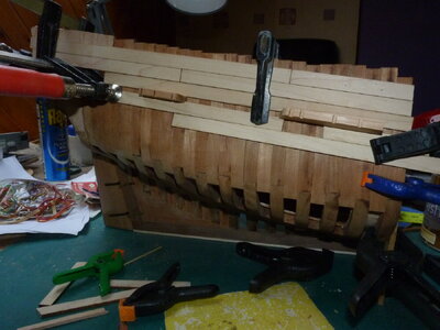
Clamping the two rows of planks below the channels was relatively easy but required the largest spring clamps that I have. The ‘F’ clamp through the window was very useful for holding down the planks at the stern.
I can’t remember but, looking at the picture, it would appear that the forward sections of planking have already been glued in place.
PICT_F_1702
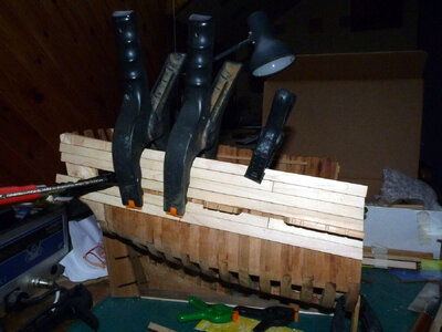
There’s one more row of hull planking still to go, and that’s as far as my clamps can reach.
PICT_F_1703
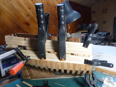
That’s as far as I could go clamping from the top, so the hull was inverted to fit the wales. At first my small spring clamps wouldn’t fit between the frames because of width of the orange jaws. These are held in place with steel pins. You can spring the jaws off without removing the pins, but you need to remove them later to replace the jaws, so you might as well remove them to start with.
The next picture shows the fitting of the starboard mid wale. As you can see, clamping methods have become much more creative.
The lower mid wale (the top one in the picture) is dry fitted.
PICT_F_1704
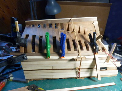
There are several minor differences in this next picture, but the significant one is the darker colour of the lower (top) mid wale. That’s because it’s now soaking wet and hopefully drying to the required shape at the aft end.
PICT_F_1705
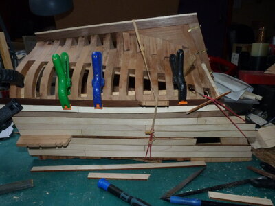
Here’s the (almost) completed starboard planking. The 1st plank has been left off for the moment so that the frame tops can be trimmed if necessary.
The channels are dry fitted and the window openings have been opened out. I’m considering veneering the sides of these.
PICT_F_1706
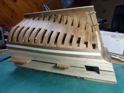
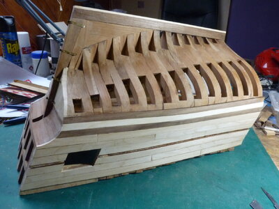
And here’s the port side:
PICT_F_1707
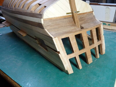
And finally, here’s how the stern turned out:
PICT_F_1708
Although they’re not required at the moment, there are some pieces needed to fill the gaps in the planking in line with the channels. These are the hull mouldings. At this stage they were strips of wood without the moulding!
Mike S. had used some dedicated scrapers to cut grooves running the full length of these pieces. I opted to try and create the same pattern.
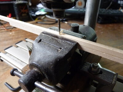
I stuck a piece of Mike’s masking tape on the side of one of the pieces and clamped it in the vice on my mini pillar drill. The other piece could be slotted into the vice above it and moved side to side because the masking tape slightly increased the clearance.
The pillar drill had been modified in the past with the addition of a screw on the ‘Z’ axis. That allowed me to set the depth of cut, and pushing the top piece of wood from side to side machined a groove along the centre of the piece.
I repeated this with the groove offset to one side. Turning the top piece of wood around created a groove on the other side.
PICT_F_1709
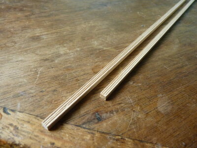
And this was the result:
PICT_F_1710
The suggested pattern was a three butt shift. I could choose my own starting point, so I opted to begin with the plank immediately above the channels. That plank starts at the forward edge of the cabin windows and runs to the front of the model.
I didn’t glue the top plank in place so that I could trim the tops of the frames at a later stage. Instead, I glued the next two rows in place. The planks below these are dry fitted in the following picture:
PICT_F_1701

Clamping the two rows of planks below the channels was relatively easy but required the largest spring clamps that I have. The ‘F’ clamp through the window was very useful for holding down the planks at the stern.
I can’t remember but, looking at the picture, it would appear that the forward sections of planking have already been glued in place.
PICT_F_1702

There’s one more row of hull planking still to go, and that’s as far as my clamps can reach.
PICT_F_1703

That’s as far as I could go clamping from the top, so the hull was inverted to fit the wales. At first my small spring clamps wouldn’t fit between the frames because of width of the orange jaws. These are held in place with steel pins. You can spring the jaws off without removing the pins, but you need to remove them later to replace the jaws, so you might as well remove them to start with.
The next picture shows the fitting of the starboard mid wale. As you can see, clamping methods have become much more creative.
The lower mid wale (the top one in the picture) is dry fitted.
PICT_F_1704

There are several minor differences in this next picture, but the significant one is the darker colour of the lower (top) mid wale. That’s because it’s now soaking wet and hopefully drying to the required shape at the aft end.
PICT_F_1705

Here’s the (almost) completed starboard planking. The 1st plank has been left off for the moment so that the frame tops can be trimmed if necessary.
The channels are dry fitted and the window openings have been opened out. I’m considering veneering the sides of these.
PICT_F_1706

And here’s the port side:
PICT_F_1707

And finally, here’s how the stern turned out:
PICT_F_1708

Although they’re not required at the moment, there are some pieces needed to fill the gaps in the planking in line with the channels. These are the hull mouldings. At this stage they were strips of wood without the moulding!
Mike S. had used some dedicated scrapers to cut grooves running the full length of these pieces. I opted to try and create the same pattern.
I stuck a piece of Mike’s masking tape on the side of one of the pieces and clamped it in the vice on my mini pillar drill. The other piece could be slotted into the vice above it and moved side to side because the masking tape slightly increased the clearance.
The pillar drill had been modified in the past with the addition of a screw on the ‘Z’ axis. That allowed me to set the depth of cut, and pushing the top piece of wood from side to side machined a groove along the centre of the piece.
I repeated this with the groove offset to one side. Turning the top piece of wood around created a groove on the other side.
PICT_F_1709

And this was the result:
PICT_F_1710

Very good planking work - well done
Thanks Uwe.
Planks that size don't want to bend!
Planks that size don't want to bend!
Remember this picture?
PICT_F_1402
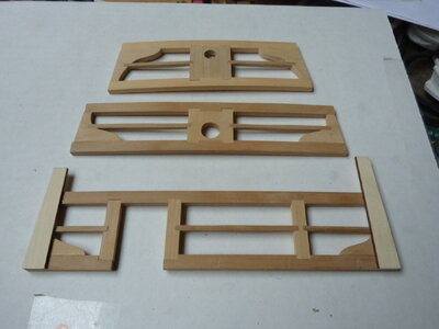
These are the poop deck beams and the upper surface of the deck should be level with the top of the bulkhead break. The top of the two short lengths of deck planking should therefore be at that level.
The problem isn’t with that bit of logic, it’s that those two bits of deck planking can’t go there. Part of that space is already spoken for - the waterways sit on the outer ends of the poop deck beams!
There aren’t any waterways for the quarterdeck, but I decided to make some, so I also needed to remove the deck planks I’d fitted there.
Time to click the undo button.
I couldn’t find the button, so I had to resort to a paint brush and water:
PICT_F_1801
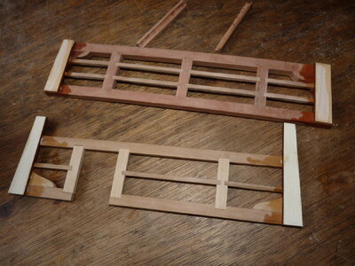
At this point I moved on to the great cabin bulkhead panelling. The back of this needs to be planked. It could all be planked, but I opted to plank up to the underside of the quarterdeck beams. I held the panel in place and drew a line under the beam.
The panel is curved to match the deck camber, but the planking curved easily.
PICT_F_1802
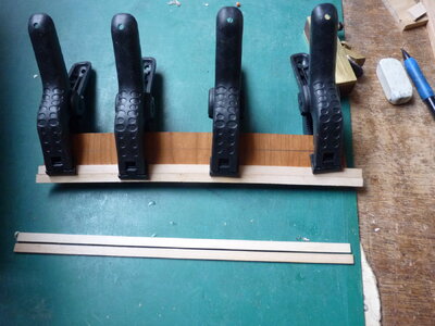
The top plank was trimmed slightly to match the pencil line. The pencil line visible in the next picture is the top of the quarterdeck beam:
PICT_F_1803
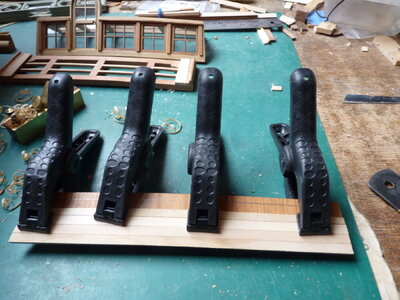
After successfully removing the planks from the quarterdeck, it’s time to put them back again, but with new waterways at the ends. I’ve also added four more sections of planking in front of the great cabin door.
PICT_F_1804
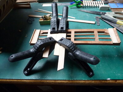
The next picture shows the three main sections.
The bulkhead break has acquired its windows, window frames, trims, door (and door handle).
I must have been on a roll at this point because I don’t have any progress pictures.
PICT_F_1805
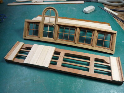
Time for a dry fit of the parts:
PICT_F_1806
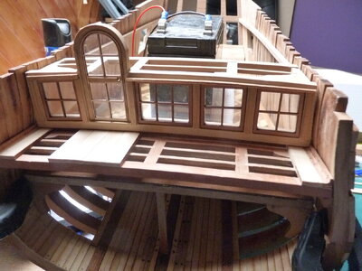
Before I glue these parts in place, I have to glue down the great cabin floor, and before I do that, I’ve some work to do below.
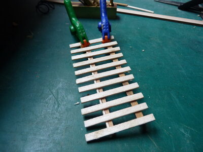
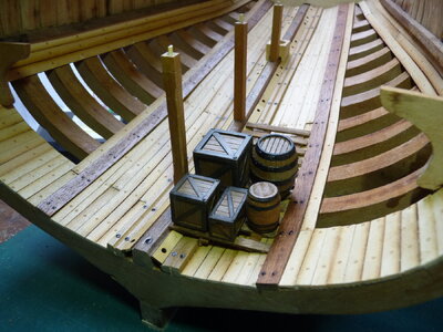
No, it’s not a garden fence, it’s more like a pallet, but it’s intended to stay put:
PICT_F_1807
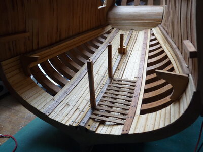
And here’s where it fits:
PICT_F_1808
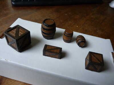
My artistic talents are definitely lacking, but I’m reasonably happy with the way these have turned out:
PICT_F_1809
And here they are aboard ship:
PICT_F_1810
I think I can now glue down the great cabin floor!
PICT_F_1402

These are the poop deck beams and the upper surface of the deck should be level with the top of the bulkhead break. The top of the two short lengths of deck planking should therefore be at that level.
The problem isn’t with that bit of logic, it’s that those two bits of deck planking can’t go there. Part of that space is already spoken for - the waterways sit on the outer ends of the poop deck beams!
There aren’t any waterways for the quarterdeck, but I decided to make some, so I also needed to remove the deck planks I’d fitted there.
Time to click the undo button.
I couldn’t find the button, so I had to resort to a paint brush and water:
PICT_F_1801

At this point I moved on to the great cabin bulkhead panelling. The back of this needs to be planked. It could all be planked, but I opted to plank up to the underside of the quarterdeck beams. I held the panel in place and drew a line under the beam.
The panel is curved to match the deck camber, but the planking curved easily.
PICT_F_1802

The top plank was trimmed slightly to match the pencil line. The pencil line visible in the next picture is the top of the quarterdeck beam:
PICT_F_1803

After successfully removing the planks from the quarterdeck, it’s time to put them back again, but with new waterways at the ends. I’ve also added four more sections of planking in front of the great cabin door.
PICT_F_1804

The next picture shows the three main sections.
The bulkhead break has acquired its windows, window frames, trims, door (and door handle).
I must have been on a roll at this point because I don’t have any progress pictures.
PICT_F_1805

Time for a dry fit of the parts:
PICT_F_1806

Before I glue these parts in place, I have to glue down the great cabin floor, and before I do that, I’ve some work to do below.
No, it’s not a garden fence, it’s more like a pallet, but it’s intended to stay put:
PICT_F_1807

And here’s where it fits:
PICT_F_1808

My artistic talents are definitely lacking, but I’m reasonably happy with the way these have turned out:
PICT_F_1809

And here they are aboard ship:
PICT_F_1810

I think I can now glue down the great cabin floor!
Nice idea and execution with the cargo - very good work
Thanks for the positive feedback folks.
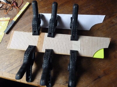
With the cabin floor in place, the next step seemed to be to fit the wall panelling. The way to do this was to copy other builders and create a paper template. That was the easy bit; however, the panelling comprises two sheets per side, so I decided to see how I could join these together.
I trimmed the ends of each sheet (where they meet) to fall on a gap in the planking and glued them edge to edge.
PICT_F_1901
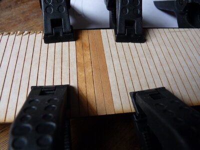
There are a couple of rulers behind the panels to keep them in line:
PICT_F_1902
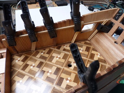
The windows were cut slightly undersized before fitting the panelling.
After gluing the panelling in place, I opted to fit a skirting board.
PICT_F_1903
Now for something completely different!
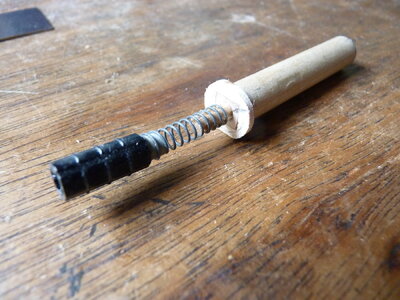
The rudder shaft on the poop deck doesn’t line up with the pintles and gudgeons on the rudder, so can it be made to work? That requires some form of universal joint. It also has to allow the rudder to be lifted to fit or remove it. A spring and a Lego shaft coupler were used to connect to the rudder.
PICT_F_1904
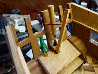
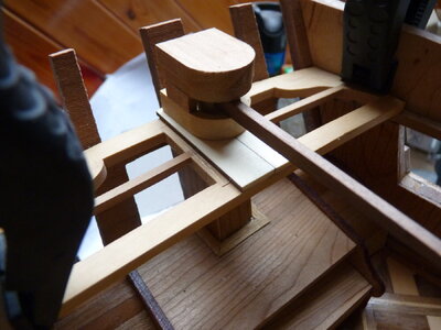
And this is how it fits into the poop deck beams:
PICT_F_1905
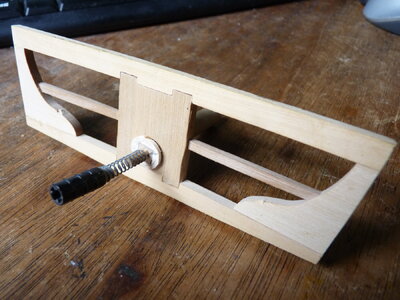
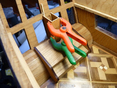
At this point, the window seat was glued in position and a block was glued to the stern window frame. This block has a hole somewhat larger than the Lego coupler to keep it in generally the correct position to connect to the rudder. As a bonus, the spring allows the rudder to be raised enough to fit or remove it.
PICT_F_1906
Although the rudder now worked, it was anything but precise! Any stiffness in the rudder caused the spring to wind up giving it a jerky operation. I thought I’d done a reasonably good job of lining up the gudgeons and pintles, but they were the only parts I could see that could causing the problem.
To check the alignment, I used a length of silver steel rod to line up the gudgeons:
PICT_F_1907
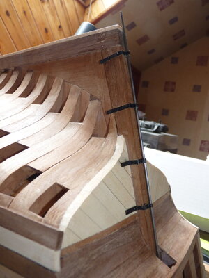
Not perfect (the pintles don’t want to be moved) but reasonable.
The rudder shaft needs to be boxed in where it passes through the great cabin and using the off-cuts of the wall panels seemed to be the logical material for the job.
I had to glue two pieces together to make each side panel.
PICT_F_1908
The front panel is three planks wide (the same width as the block I fitted earlier) but I had to make this from two pieces also.
Note the whopping great hole in the seat. That will need some attention later,
PICT_F_1909
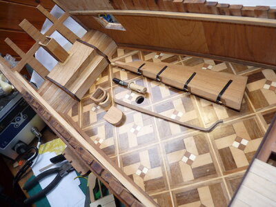
Here’s the kit of parts to fit the rudder.
Note that the hole in the seat has disappeared under three pieces of oak veneer and a rectangular hole has appeared in the rudder shaft.
PICT_F_1910
This shows the above parts dry-fitted.
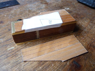
There was something odd about how the first and second sections of the tiller cover fitted together. There’s a slot left open.at the back of these pieces. I glued a strip of wood in the bottom piece to close the gap.
PICT_F_1911
I trimmed the ends of each sheet (where they meet) to fall on a gap in the planking and glued them edge to edge.
PICT_F_1901

There are a couple of rulers behind the panels to keep them in line:
PICT_F_1902

The windows were cut slightly undersized before fitting the panelling.
After gluing the panelling in place, I opted to fit a skirting board.
PICT_F_1903

Now for something completely different!
The rudder shaft on the poop deck doesn’t line up with the pintles and gudgeons on the rudder, so can it be made to work? That requires some form of universal joint. It also has to allow the rudder to be lifted to fit or remove it. A spring and a Lego shaft coupler were used to connect to the rudder.
PICT_F_1904

And this is how it fits into the poop deck beams:
PICT_F_1905

At this point, the window seat was glued in position and a block was glued to the stern window frame. This block has a hole somewhat larger than the Lego coupler to keep it in generally the correct position to connect to the rudder. As a bonus, the spring allows the rudder to be raised enough to fit or remove it.
PICT_F_1906

Although the rudder now worked, it was anything but precise! Any stiffness in the rudder caused the spring to wind up giving it a jerky operation. I thought I’d done a reasonably good job of lining up the gudgeons and pintles, but they were the only parts I could see that could causing the problem.
To check the alignment, I used a length of silver steel rod to line up the gudgeons:
PICT_F_1907

Not perfect (the pintles don’t want to be moved) but reasonable.
The rudder shaft needs to be boxed in where it passes through the great cabin and using the off-cuts of the wall panels seemed to be the logical material for the job.
I had to glue two pieces together to make each side panel.
PICT_F_1908

The front panel is three planks wide (the same width as the block I fitted earlier) but I had to make this from two pieces also.
Note the whopping great hole in the seat. That will need some attention later,
PICT_F_1909

Here’s the kit of parts to fit the rudder.
Note that the hole in the seat has disappeared under three pieces of oak veneer and a rectangular hole has appeared in the rudder shaft.
PICT_F_1910

This shows the above parts dry-fitted.
There was something odd about how the first and second sections of the tiller cover fitted together. There’s a slot left open.at the back of these pieces. I glued a strip of wood in the bottom piece to close the gap.
PICT_F_1911

Canoe21
Lawrence
Hello Arthur, Very nice and interesting work that you have put into your HMY Fubbs. You have given me a lot of very nice ideas about how to approach this great kit build. I am very far behind you giving me the advantage to see just how you approached things. Sure do miss Mikes MSB build log as it was gone before I started my build.
Regards Lawrence
Regards Lawrence
Thanks for the feedback Lawrence.
Yes, the loss of Mike's log was a major set back.
Thanks also for all the 'Likes'.
Yes, the loss of Mike's log was a major set back.
Thanks also for all the 'Likes'.
Following my last log entry, Mike emailed me some additional information re fitting the rudder on the prototype. I asked if he was happy for me to post the information here. He replied to say "You are more than welcome to post any of my HMY Fubbs material on SOS. I have sent these updates to all the other Weasels via email as well."
So the following information is for the benefit of all those following the various Fubbs build logs.
Here are additional photos of my built rudder/tiller that were not included on the USB drive. All of this was posted on my build log at MSB.
Mike Shanks
So the following information is for the benefit of all those following the various Fubbs build logs.
*********************************
Here are additional photos of my built rudder/tiller that were not included on the USB drive. All of this was posted on my build log at MSB.
- The assembled rudder should be tapered both front to rear and top to bottom as shown in the photos. Mike41 left his big and chunky so I guess this is optional.
- I scratch built pintles/grudgens from blackened brass as shown in the photos for my rudder. I also added chains and other small details.
- The upper stem of the rudder needs to be both shortened and shaped down significantly to pass through the opening in the counter. I removed a lot of material from mine and ended up shaping it sorta round.
- The edges of the rudder should have a 30 - 45 degree camfer cut in it to allow movement. Technically there should also be a matching camfer on the stern post.
- I test fitted my rudder many many times before finally getting the fitment to my liking. I think the rudder was one of the last things I installed.
- I also scratch-built a trunk inside the great cabin that covered the rudder stem as it passed up through to the upper deck. See photos.
- I used a simple brass pin with a matching hole to merge the tiller dowel with the rudder stem to make it all fit together. See photos.
- You will also notice I painted the upper portion of my rudder stem black and added some hand painted artwork.
Mike Shanks
Attachments
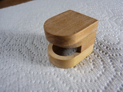
The last picture I posted in this build log (PICT_F_1911) was of the rudder cover. At the time, I commented on the way it looked and that I’d added a piece to close off a gap at the rear of the cover.
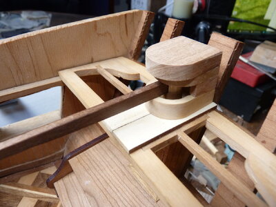
I’ve since realised that the cover was incorrectly assembled. I’d aligned the parts such that the three curved sections were aligned at the front. I should have aligned all four pieces at the rear.
This is the way the maker intended it to look:
PICT_F_2001
PICT_F_2002
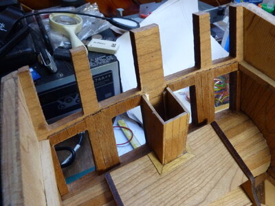
Next job was a little more planking around the stern windows.
I temporarily fitted the stern poop deck beams in place and drew a pencil line on the transom below the beams. That showed where the top of the new planking should finish.
PICT_F_2003
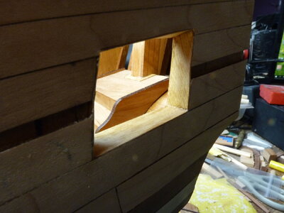
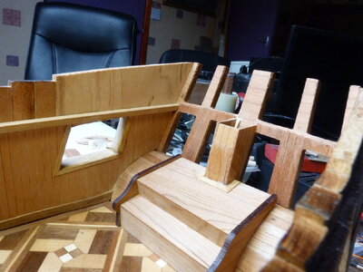
At this point I decided to tidy up the window openings in the ship’s sides.
I cleaned up the two openings and then glued oak veneer strips around each opening:
PICT_F_2004
Finally, I added a simple frame around the inside of the windows:
PICT_F_2005
I’ve since realised that the cover was incorrectly assembled. I’d aligned the parts such that the three curved sections were aligned at the front. I should have aligned all four pieces at the rear.
This is the way the maker intended it to look:
PICT_F_2001

PICT_F_2002

Next job was a little more planking around the stern windows.
I temporarily fitted the stern poop deck beams in place and drew a pencil line on the transom below the beams. That showed where the top of the new planking should finish.
PICT_F_2003

At this point I decided to tidy up the window openings in the ship’s sides.
I cleaned up the two openings and then glued oak veneer strips around each opening:
PICT_F_2004

Finally, I added a simple frame around the inside of the windows:
PICT_F_2005

Progressing well Arthur.
Looks super good Arthur. You've blown past me, it's spring here so time for me to get back to work. Now I can use some of your tips and tricks.
Thanks for the comments and all the 'Likes', they're much appreciated.


