• Ships of Scale has incorportated an extra level of security when you log In. Please follow on-screen prompts to acknowledge that you are not a robot via a "Check Box" or a "Pictorial Check Box Puzzle". This is needed due to higher level of AI Activity Security.
  • SUBSCRIBE TO SHIPS IN SCALE TODAY!

    The beloved Ships in Scale Magazine is back and charting a new course for 2026!
    Discover new skills, new techniques, and new inspirations in every issue.

    NOTE THAT OUR NEXT ISSUE WILL BE July/August 2026
  • Win a Free Custom Engraved Brass Coin!!!
    As a way to introduce our brass coins to the community, we will raffle off a free coin during the month of August. Follow link ABOVE for instructions for entering.

How to make gunport wreaths

I once had ambitions in that direction. The complexity, lack of contemporary plans, the time - I chased several plans (Prince, Royal Katherine) that leave much to be desired. I even followed Antony Deane's design instructions for recreating Royal Charles or Royal James. Then my sanity returned. I do highly recommend taking the time to follow Deane's design method. I put my level of understanding plans at a more serious level. I was trying to find a way to loft frames without plotting them. Deane only gives directions for producing three stations. I thought it was Deane being lazy. I was wrong about that. He only used three. Battens were used to connect the three points plus the stem and stern. Once they were fair with a smooth run, the other stations are plotted - exactly what I was trying to avoid.

I am going Georgian Royal Navy - 1719 - 1776. instead of 17th C. I just picked 1670 because that is my guide star - the conditions and materials do not change until maybe the 20th C.


I do not think that the acidity of Titebond II is something to worry about - if the model is a case that has enough ventilation for volume exchange Q12H to Q24H. There is not all that much volume of acidic acid to begin with. Being volatile at RT, it will out gas in weeks if not faster. Lineco Neutral PVA is pH7, but I do not think that the bond strength come near that of carpenter's PVA.


Repeating something I wrote recently:

Someone asked in the Chinese junk thread "what will become of MY models in 90 years". It got me to thinking. To survive with following generations - whose world will be much more constrained and less privileged than ours - models will have to be cased and small enough to rate having shelf space. For 1:48, 1:60, 1:72 a model and its case is huge, heavy, and the case unsustainably expensive.
A much smaller case would be easier to fabricate and the glazing be thin - low cost per size - light weight - with no need for any safety factors. As long as you stay far away from the "better living thru Chemistry materials, stability over time should be no problem.

I am at present exploring possibility of 1:120 - which is essentially 1:128 or 3/32":1' for anyone who wishes to stay Imperial. It is an academic exercise for me. The savings on wood are huge and the actual build goes much faster. Fabricating those parts that are too small to use wood to build them is probably going to be a major challenge.
For HMS Sovereign of the Seas from 1637, Deane's Treatise of 1670 is far too late and is not the basis upon which the Sovereign was designed. Peter Pett documented the hull molding of the Sovereign, so using the information provided by the very man who built the ship is a no brainer. The Petts had their own methods of designing hulls in the earlier days. John McKay made the mistake of applying Deane's methods to the Sovereign. Square peg, round hole. If I was building a late 17th century model, then Deane's Treatise would probably be the way to go.

Too bad Lineco Neutral PVA is not as strong as Titebond II. I really like how fast Titebond II sets up, especially when the coating is thin. As long as a plank is pre-formed to the hull shape and not springy from being forced in place, Titebond II works perfectly. It's worth the time to pre-bend your planks before attachment since it actually saves you time over that spent waiting for a springy plank to stay in place with almost fully cured glue.

Perhaps smaller vessels would last longer, perhaps not. The factors involved with which models are chosen to last the ages are hard to fathom, and often luck has more to do with it than anything. Building smaller than 1:100 for me creates difficulty in maintaining the level of detail I prefer. Other members on this forum are much better at fabricating micro-details than I am.

 
John McKay made the mistake of applying Deane's methods to the Sovereign. Square peg, round hole.
To my eye, Deane's method produces a very distinctive hull form and one that seems to be essentially the same regardless of the size of the vessel. I have been mentally categorizing all of the methods used from Matthew Baker until very early in the 18th C. as whole molding variations.

Too bad Lineco Neutral PVA is not as strong as Titebond II. I really like how fast Titebond II sets up, especially when the coating is thin.
I wrote that I "think" that Lineco is not as strong. I have no actual data to back that up. I have been using Titebond II since the early 1970's and have had to reason to change.
I apply a total wet layer - translucent - to both surfaces. No pools of yellow. I use a mini sponge stick applicator - well spreader - excess absorber - actually. A use a Babebot (4oz) as my glue source. As long as I keep the small tip opening clear of the polymerized remains from last time. It has first class control on volume and location.
I have way more than enough sponge stock from tool packing. The 'you can squish it' foam not the dense white "starfoam" (KY) peanut type. One to three round toothpicks dipped (stuck down the tube opening) in Duco make a good handle. Pink works - this newer black -but it is more flimsy - the blue works better with Duco.

I concur with your concept of 1:100 - It pushes the limits of wood - the really dense species become the necessary stock - and the work goes from replication at a small scale to illusion at miniature scale. At least that is how I view it. I am fast coming up on finding out if I have the chops to pull it off. Up until this flood light enveloped me a couple of months ago, I was as averse to miniature as you seem to be.
 
To my eye, Deane's method produces a very distinctive hull form and one that seems to be essentially the same regardless of the size of the vessel. I have been mentally categorizing all of the methods used from Matthew Baker until very early in the 18th C. as whole molding variations.


I wrote that I "think" that Lineco is not as strong. I have no actual data to back that up. I have been using Titebond II since the early 1970's and have had to reason to change.
I apply a total wet layer - translucent - to both surfaces. No pools of yellow. I use a mini sponge stick applicator - well spreader - excess absorber - actually. A use a Babebot (4oz) as my glue source. As long as I keep the small tip opening clear of the polymerized remains from last time. It has first class control on volume and location.
I have way more than enough sponge stock from tool packing. The 'you can squish it' foam not the dense white "starfoam" (KY) peanut type. One to three round toothpicks dipped (stuck down the tube opening) in Duco make a good handle. Pink works - this newer black -but it is more flimsy - the blue works better with Duco.

I concur with your concept of 1:100 - It pushes the limits of wood - the really dense species become the necessary stock - and the work goes from replication at a small scale to illusion at miniature scale. At least that is how I view it. I am fast coming up on finding out if I have the chops to pull it off. Up until this flood light enveloped me a couple of months ago, I was as averse to miniature as you seem to be.
Thanks for sharing the details of your methods! Useful stuff.

My last model at 1:100 showed the limitations of coarse grain wood as you observed. Walnut is hard to bend in short radii, oak appears like a bundle of straws at that scale, and the cross grain banding and speckling of sapele and mahogany overwhelms the visibility of the plank seams entirely. Up close, these problems make fabricating difficult and detract from appearance when observed up close. Boxwood is not available here, so I turned to cherry as a good wood for smaller grain and rich color, with walnut for railings, trim and other enhancements. In order to really get good wood, you have to buy the more expensive species like box, pear, apply, etc from someone like Dave's Lumberyard. Maple close grained but too light in color and dark stain obscures any grain character.
 
Maple close grained but too light in color and dark stain obscures any grain character.
Hard Maple is my choice. Stain - bad - aniline alcohol dye solution - good A molecular dye accents grain, not obscures it. It does not go real dark but garnet shellac flakes make a solution which produces a totally transparent layer. Maroon or grey or white Scotchbrite pads will knock down any sheen.

I have a new idea based on very old practice, but first I have to experiment with it and then I want it to be a big reveal if it works.
 
Hard Maple is my choice. Stain - bad - aniline alcohol dye solution - good A molecular dye accents grain, not obscures it. It does not go real dark but garnet shellac flakes make a solution which produces a totally transparent layer. Maroon or grey or white Scotchbrite pads will knock down any sheen.

I have a new idea based on very old practice, but first I have to experiment with it and then I want it to be a big reveal if it works.
Thanks for that great tip! I some hard maple blocks. Perhaps I should hit the saw and use some of it on the next build. I used red-brown tinted shellac on the red oak bathroom cabinets I mad once before, and the color pops while letting the grain show through, but never tried it on model parts. Let us know how your experiment works out. Thanks again!
 
Deane only gives directions for producing three stations. I thought it was Deane being lazy. I was wrong about that. He only used three. Battens were used to connect the three points plus the stem and stern. Once they were fair with a smooth run, the other stations are plotted

You might wish to take another look at this. In fact, in his manuscript from around 1670, Deane sets out a geometric procedure for shaping all the frames’ contours along the entire length of the keel and at any point along it, though he does indeed describe this procedure in detail for only three example frames, as the method is identical for all frames and it would serve no purpose to repeat the lengthy description of the same procedure for many dozen frames (or bends).

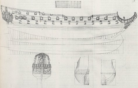
Below is one of the illustrations from Deane’s manuscript, which contains a generated complete body plan by the author, featuring numerous frames (bends) drawn in an indisputably geometric manner, according to a uniform procedure:

Anthony Deane's two-decker.jpg​


It may also be added that this is a method employing three circular arcs to form the underwater section of the hull, which almost certainly replicates Venetian methods that were subsequently introduced in England in the second half of the 16th century.
 
You might wish to take another look at this. In fact, in his manuscript from around 1670, Deane sets out a geometric procedure for shaping all the frames’ contours along the entire length of the keel and at any point along it, though he does indeed describe this procedure in detail for only three example frames, as the method is identical for all frames and it would serve no purpose to repeat the lengthy description of the same procedure for many dozen frames (or bends).
Actually - it is for the stations - which are the midline of bends.
The reason I thought that three stations was all is that I could not discern the variable for each of the other stations. If the three are just examples, he does not provide an answer to what to use for all of the others. It has been decades but I did pick one variable and drew all of the other stations. I think there was a deformity. There are the drawings of Hollanders in frame with three bends and full size battens making a basket and data points for the other frames. There is something else that I failed to make a reference card for. It had the three stations being moved slightly to refine the run of the WL If Deane did do it that way, once there were enough WL - the same Body plan can be had by plotting the points from the WL.

17th C. golden sculpture palaces are an old itch, but I am just throwing possibilities at the wall to see what sticks. For the sake of my sanity and to keep from going into a fugue state because of too many choices, I have gone 18th C. There are a lot of design plans - most of which have never been modeled. Or at least modeled by anyone who admitted to doing it. A few "stars" are way, way, way, overdone but almost all of the vessels that sailed with them have been ignored.
 
The reason I thought that three stations was all is that I could not discern the variable for each of the other stations. If the three are just examples, he does not provide an answer to what to use for all of the others.

These ‘variables’ are nothing more than longitudinal design lines, and for this particular case they are all described in the text and also shown on Deane’s plan above. They can and should be applied to the shaping of all the frames.

I did pick one variable and drew all of the other stations. I think there was a deformity.

This is quite possible, as Deane drew the so-called ‘bottom hollowing curves’, connecting the hull body proper to the keel, in a simplified and not entirely accurate manner; this was because his manuscript was drawn up at the request and for the benefit of a layman unfamiliar with the subject – and in any case with no prospect of putting this information into practice – namely Samuel Pepys.

There are the drawings of Hollanders in frame with three bends and full size battens making a basket and data points for the other frames.

These three bends in Dutch-style designs are most certainly the master frame and both quarter frames, which are, in fact, essential to their distinct design method — one that also allows for the geometric pre-definition of all frames/bends along the entire length of the keel and at any point along it.

To simplify matters somewhat, physical battens were particularly useful for ensuring that all the previously geometrically predefined frames had been constructed and fitted with sufficient accuracy; and, as a rule, they did not fulfil an independent design role in their own right, except in specific cases, such as at the very ends of the hull. The situation is somewhat different with design diagonals, but that is another story.

It had the three stations being moved slightly to refine the run of the WL If Deane did do it that way, once there were enough WL - the same Body plan can be had by plotting the points from the WL.

When applied correctly, early conceptual methods did not require the use of waterlines to achieve fairand, at the same time, seafaringly desirable shapes, and one managed perfectly well without them. It is only today, usually for the reconstruction of ships from those early periods, that waterlines have come to widely and conveniently replace knowledge of the old design methods.
 
Back
Top