• Win a Free Custom Engraved Brass Coin!!!
    As a way to introduce our brass coins to the community, we will raffle off a free coin during the month of August. Follow link ABOVE for instructions for entering.

I have decided to start over…….

Joined
Jul 12, 2023
Messages
70
Points
78

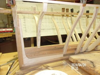
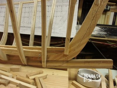
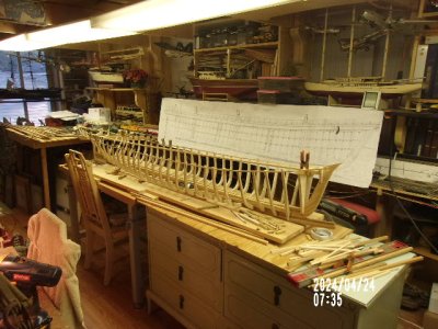
Having recently decided to “pick up where I left off” I have confirmed I have a good project and tracked down a lot of history and sourced some very informative copies of the original plans. However auditing my approach and early attempt at some frame parts I see I was heading towards some serious issues with fitting the frames to the keel, mainly caused by the deadwood, keelson and frame interface. I have decided to start again from scratch, use fewer frames and finalise the jointing arrangement. One question should the internal surface of the keel be fully planked or use stringers as is suggested on the plans. Are plywood frames an alternative to totally fabricated and pinned frames?
 
Hello Seagull Shipwright,

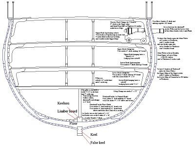
What ship is this to be? Frames sat on the keel differently in different nations and eras. Not sure what you mean about the keel being planked internally. Maybe the cross section will help understand more clearly. Ignore the dimensions, they are for a particular ship.
Allan
1759279634677.jpeg
 
Are plywood frames an alternative to totally fabricated and pinned frames?

Plywood is a poor candidate for frames. The edges of plywood, being laminations of alternating grain direction, are difficult to fair because they don't plane or, for that matter, sand, very well at all. Cutting full length frames from solid stock is also a poor practice because the curved shape of frames virtually guarantees grain runout which will result at some point along the length of the frame with grain running across the frame which creates a very weak spot that will almost certainly break. Moreover, due to the edge grain presented on the edges of plywood, it is a poor surface for gluing or trying to drive pins or trunnels into.

The practice that is seen when fully framed models are built which purport to replicate the actual construction details of a vessel by cutting futtocks and pinning them, while impressive in a "masterpiece" project that will take years to complete, is only necessary when one undertakes the challenges of such models. For fully planked models where the frames serve to define the shape of the hull, but not to depict the actual period construction practices, one useful solution is to laminate wide, but relatively short, strips of wood with the butts staggered, such that the grain of each strip is more or less parallel to the direction of the frame's length. This yields a "frame shaped" laminated piece out of which the actual frame shape can be sawn without grain crossing the narrow width of the frame. I have found clear birch wood (I think) tongue depressor sticks, which are about 3/4" X 1/16" X 6" and can be inexpensively purchased in bulk from most craft stores, work well for this purpose because the wood is correct for the purpose, as is the size. Tongue depressors can also easily be cut with a standard classroom paper cutter or a pair of large sharp shears... or sawn, at the required angles to form the frame shape, and then glued up with PVA and clamped with binder clips to set overnight. While these frame blanks are laminated, they don't have plywood's disadvantage of presenting edge grain at alternating laminations and can be sanded much like solid wood.

When purchasing tongue depressors, note that some are sold as "popsicle sticks," or "craft sticks," and others as "tongue depressors" and they come in a variety of sizes. I'm not certain, but I believe the tongue depressors are slightly thinner than the popsicle sticks and I'd advise getting the thinner ones because they are easier to cut. Don't worry about buying too many. If you do any amount of modeling, you'll find their hard "white" wood with no visible grain or tendency to splinter or "fuzz," is practically a "poor man's boxwood or holly" and useful for all sorts of modeling purposes.

See: https://www.amazon.com/s?k=tongue+depressor+for+craft&adgrpid=1337008617574518&hvadid=83563313357721&hvbmt=be&hvdev=c&hvlocphy=88716&hvnetw=o&hvqmt=e&hvtargid=kwd-83564162493210:loc-190&hydadcr=4831_13229909&mcid=72b204a64dac39a09cd92fc707007c3e&msclkid=5bb074256d751189d5fc1cf99d165158&tag=mh0b-20&ref=pd_sl_u0b9kc6qs_e
 
Last edited:
Bob and Ab, thanks for the heads up. It looks like Plywood is a non-starter and I will heed your advice.

As you can see from my early posts I bought some Sycamore and cut it down to size. Then jointed as futtocks with pinned joints. Took a very long time and ran into problems fitting to keel.

Just ordered the tongue depressors and will assemble the laminate as recommended to the desired thickness, then cut and sand.

Another question if I may….. I have got my head around the frames that sit directly on the keel, but wondered how to find the height above the keel on the deadwood. Can someone explain it for me?

Thanks everyone, whilst out of my depth still I have some new options to explore.
 
I have got my head around the frames that sit directly on the keel but wondered how to find the height above the keel on the deadwood. Can someone explain it for me?

I'm not understanding your question. I suspect there's a lack of fluency with the nomenclature. Frames are fastened to the keel in a variety of ways. Sometimes floor timbers are bolted to the top of the keel, and the frames are bolted to the sides of the floor timbers. Sometimes frame heels are also let into the top of the keel adjacent to the rabbet. Sometimes the frames are constructed so that the floor timber is integral with the entire frame assembly which is then bolted to the top of the keel. Frame heels at the ends of a vessel are often fastened to the sides of the deadwood or stem assembly. Bottom line, it depends on the shape of the hull and the method of assembly. If you have plans, they should show the rabbet line and that would be your benchmark for the intersection of frame heel, rabbet, and garboard.

Of course, if you are building a planked hull and nobody's going to see the frames, you can fashion any sort of support for the planking at the ends that you wish, since nobody's going to ever see what's beneath it. This one reason why many experienced scratch modelers opt to avoid fiddling with structural framing at all and simply construct hull shapes using the lift, or "bread and butter," method in which the waterlines are used to stack up into an accurate hull shape and the excess "steps" between the waterlines simply removed and the hull shape faired using the cut waterline shapes as guides.
 
You might get more detailed and specific responses if you could let us know what ship you are building.
Thanks
Allan
 
Bob and Allan, thanks again for your support. The vessel I am building is the HMP Seagull from the original c1830 drawings. I have posted the drawings in my thread Seagull in the section on SOS Build Logs from Scratch or Plans. Thanks for the tips on joining the frames on the keel and the deadwood. Whilst I can set any frame at the correct spacing and location along the length of the keel the frames that are not directly on the keel i.e. on the deadwood, I am not sure how to establish or confirm the height above the keel. Do you use the top of the deadwood or the bearding line as the datum?

Thanks again Seagull Shipwright.
 
Do you use the top of the deadwood or the bearding line as the datum?
If there is bearding line on the deadwood forward and aft, the shelf along the line is where the frames usually ended. The problem with the plans I found is that they do not show the lines. I was surprised not to see a body plan. Did you find a contemporary body plan for Seagull 1830 at RMG or was it elsewhere?
Thanks
Allan
1759453121045.png
 
Last edited:
Allan,

I purchased nearly all of the available plans from the Royal Maritime Museum Greenwich. This included the original proposals from 1829 until the launch as wells a second set referring to the modifications. The bearding line appears on the bow, but runs out toward the stern at frame 21. I assume it runs up to the top of the stern post? I will use the bearding line as the datum. If that is the case there is a good chance the already fabricated frames will be usable going forward.

ZAZ6157-Seagull1831-Lines.jpeg
 
Sorry SS, I do not see any bearding line anywhere nor can I see a line running out at station 21. (The station numbers are not necessarily frame numbers) It seems like you are referring to the rabbet that ends at station 19 but this has nothing to do with where the frames end on the deadwood both forward and aft. An example showing both the rabbet and bearding line is below. If there was a framing plan like the ones below it would be a huge help. You can see exactly where the frames end well above the rabbet.

Can you post the ZAZ number of the modification drawings? THANK YOU :)

Allan


1759503395667.png
1759503657228.png
 
Last edited:
Having recently decided to “pick up where I left off” I have confirmed I have a good project and tracked down a lot of history and sourced some very informative copies of the original plans. However auditing my approach and early attempt at some frame parts I see I was heading towards some serious issues with fitting the frames to the keel, mainly caused by the deadwood, keelson and frame interface. I have decided to start again from scratch, use fewer frames and finalise the jointing arrangement. One question should the internal surface of the keel be fully planked or use stringers as is suggested on the plans. Are plywood frames an alternative to totally fabricated and pinned frames?
Read my build under Great Republic at 1;48 scale by Norgale. I have been building a model like yours and I've run into many of the same problems you are or will be dealing with. I don't agree with some people here as to the material to use and like the width of the planks and the length. These are two major things that ou will have to decide on your own as they and other solutions work fine. I'll be happy to discuss my experiences with you any time. Pete (Norgale)

100_0001 - Copy.JPG

100_0005 - Copy.JPG

100_0006.JPG

100_0008 - Copy.JPG
 
SS
I found your log. I tracked down your projects plans. I figure that you could have as much as lb 300 invested so far.

In my experience a schooner is an excellent choice as a first POF scratch build. Your choice of Sycamore (Acer pseudoplatanus) a hard Maple is an excellent one. It is functionally the same as Boxwood.

Over here what is named Sycamore is something totally different. It is a similar yellow and about as hard but the grain is inappropriate (sold as Lacewood if cut on the correct plane). The fibers roll - no crisp edges - it stinks when cut. I bought some by mistake - misunderstanding what Underhill meant when he recommended it. It is good for jigs and sanding blocks.

Were I doing this as a first scratch POF build - there are definite choices that I would make.
What you have:
I see that ZAZ6144 shows just how Seagull was framed. My JPEG is far too small to read the script contained. It looks like economy Fir framing. What we over there call Pine. For vessels with expected to have a short half-life, needed in a hurry.
It is all single frames.
The floors and what I guess to be half floors are a solid wall on top of the keel. Both are 12.5" sided. This means that the stations are at 50" intervals.
There are four frames between each station.
Futtock 1 (F1) is sided less than its half floor. I cannot measure but F2 appears to be the same sided.
F3 is sided less than F1 and F4 is probably the same as F3.
Using a "Z" scarph for the HF stack is stronger than the hidden dowel joining the timbers in the floor stack. Both are frustratingly weak end grain to end grain bonds in a model. I would not think of replicating that.
To my eye there is no art or style to the actual framing. It is close to being a solid wall of framing. I see no interest in displaying it - unless I used it as a demonstration model in an engineering class.
I would opt for stylized framing. All bends - room = space.

I would not use the keel as a gauge for bend height.
If you take this as the encouragement that I intend perhaps a framing style, ways to deal with deadwood, and cants vs whole frames all the way can be explored.
This is after all an initial effort. Compromises are appropriate. When you get to where you do not have to ask you will know which style is yours.

Dean
 
Hi Dean and thanks for your reply. I had more trouble with my frames than anything else and redid them three times before I got close to having a good fairing.. I was told not to us plywood and with a smaller scale boat using much thinner plywood that would be true. However with the Great Republic being so large I finally went with 1/2" plywood. I wanted a wide landing for the hull planks anyway and after the hull is complete none of them would be visible. I also used larger various pieces of wood than what my plans called for because I wanted strength in the framing because of the weight this model will have in the end. Adding in the three interior decks helped with the strength too. The keel and keelsons are all Poplar and all the ceiling, decks and hull planking are basswood. One thing that I disagree on is what to use for outside planking. I went with basswood and used two foot long sticks but all were 1/4" width by 1/8 thick. years ago I found that the narrower a plank was the better it followed the curves of the hull. That's where I disagree with some other guys. After the planks are sanded smooth and filled and painted the planks don't show very much anyway. If I ever build another POF I will have all the frames cut out by CNC machine and save myself a ton of mistakes and money. Right now I'm waiting for some rolls of copper 1MM thick for my hull coppering so I've been cleaning and rearranging my hobby room and throwing lots of junk out. What a mess that room was. Soon as I get the copper and figure out how to make it look like copper plates I'll be back to work again. Pete
 
Last edited:
Pete,

Pretty large scale there. That does change a lot. In your place, I would have used construction Pine. The frames would be a solid wall. With a copper bottom - I would add the plank thickness to the frame patterns and fix the copper directly. Doing planking over a solid hull that was then covered with cooper would be pointless. I think it would be necessary but also a total PITA to have the framing above the copper be inside the planking. I would properly plank the topside. Even at your scale I would not give the bottom the Small Pox by attempting to simulate the actual millions of copper nails that were hammered flat to the plates anyway. I would see if I could use MM - Model Master chemicals to get old penny. AND a totally unrealistic verdigris streaking on the whole swimming body and not just at the air water zone- because I think the look is cool. If the hull was a lesser scale, and I was compelled to do a copper sheathing I would probably use linen bond dissertation paper. Cut into plates using a guillotine after priming and using actual copper MM paint. Being paper, Titebond should bond the plates to the Pine right well. This is pure theory - I am addicted to a stylized below the keel visible framing.
However, should I have done all that a crane would be needed to move the hull.
 
My JPEG is far too small to read the script contained. It looks like economy Fir framing
Hi Dean

From what I can make out:
-For the floors and cross pieces, African timber --- (I have no idea what species they used but two common species taken to Britain were teak and mahogany
-First futtocks oak or African timber
-Toptimbers cedar

None of these are good for modeling so I would go with some favorite close grain species.

Allan
 
Allan,

I can think of no species of wood used in shipbuilding that would scale acceptably as model stock. I have seen Oak used in a model and the grain tends to dominate and distract - it taking most of the stage.

I was channeling what was done using Pine for some of the Cherokee/Rolla sisters . There is also the square tuck with some Fir/Pine builds in the early 19C. instead of the 16C/early 17C hulls when a square tuck was usual..
In the frames partnered to the floor timber frames my understanding is that there were three options for the timbers resting on the keel.
1. A large cross chock joining F1 port to F1 stbd.
2. A long arm F1 port butting a short arm F1 stbd alternating with a short arm F1 port butting a long arm F1 stbd.
3. A half floor. I use a general rule that seems to generally hold over my 200 year time span of focus. The floor length was 60% of the beam width. So I wet finger the half frame as being about 35% of the beam width. For Seagull ZAZ6144 shows a serious length for the F1 frame over the keel timber. This says half floor to me.
4. The ASA expressly forbids having F1 P butt directly against F1 S at the keel. The potential hull disaster that doing this could produce has my imagination seeing this as being forbidden at least as far back as the 15C or 16thC. It was probably shear luck that anyone survived to report this bad idea producing the first broken back sinking.

Having extracted the timber patterns for well over 100 hulls, this 60% rule has worked. There has been no over running of the turn of the bilge. Navy Board stylized framing has floors that are longer than 60% and they almost always run up the turn of the bilge. They look like the the horns of a Texas Longhorn bull. No close packing on framing stock much wasted stock.
This would not work for a hull with significant deadrise at the deadflat. Model stock can easily be wide enough. Finding an actual tree that could do it for a full size hull? A snipe hunt?

Dean
 
Thank you all for your comments and input, much to consider. I am finishing up my antique restoration project to clear the decks for the model build. I am also continuing my historical research to finalise the finer points of my model. Finally I am reviewing the frames I have already made in sycamore with tree nailed and glued and pinned joints.

Allan you requested the drawing identifying numbers….. in date order:-

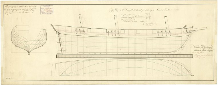
ZAZ 6157 13th July 1829 “A Draft Proposal for Building Schooner Packets”

Elevation, Half Breadth Plan, Sections and General metrics.

3 masted Schooner.

Issued to Chatham 26th August 1829

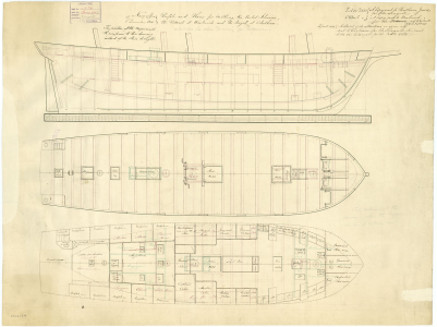
ZAZ6144 26th August 1829 “Sketches for Building at Chatham” this details the frames that appear to be butting up as Dean has observed. Is it possible to space the frames wider so the lower decks can be viewed, at least from one side?

There has obviously been changes as:-

ZAZ6157 6th December 1830 “Profile and Plans for Building Two Packet Schooners…….the Seagull at Chatham

1832 Paul bits and Mizzen mast modifications.

ZAZ6158 6th December 1830 “Midship Section of the Petterel and Seagull showing internal and external planking.

Then the significant changes…..ZAZ6156, ZAZ6154 and ZAZ6155.
My research suggests that the hull was constructed and launched in 21st November 1831. In October 1832 she was stored at Sheerness and in 1834 her completion was requested to be brought forward.

My take from this is the frames and planking form 1829 plus the modifications as detailed will allow the model to as she went into service.

So……
Plywood Out and sycamore etc In

Rabbit lines available as is the height of the deadwood.

Need to place frames on the deadwood.

I have read that measurements from the stern frame sections intersect the deadwood (not sure I get this!) can derive the bearding line.

Is it possible to construct the model with the frames/locations as drawn or with some intermediate, or is it essential to make all the 12.5” frames and pack them in solidly?

Thanks again to all respondents…….too muck to learn and so little time.

SS
 
Back
Top