You are close!
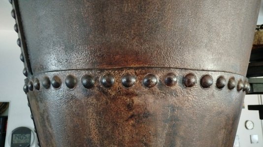
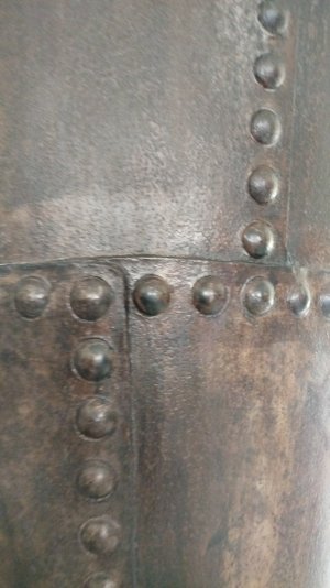
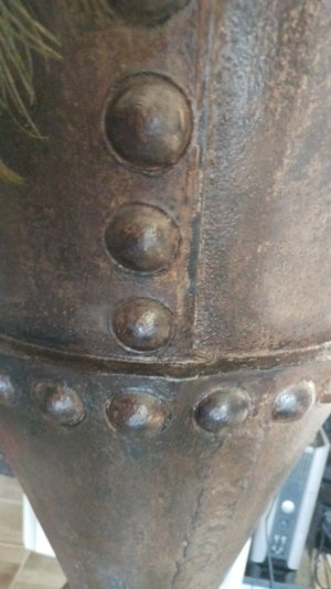
The DIN (Deutshe Industrie Norm) regarding rivet definitions seems to go up to 36 mm - 1.4 inch. This is also the size I remember from the Rivets of the steel roof structure of the "Wiener Rathaus", where we had to do some few 100 rivet replacements. Spacing seems to have varied from one to two head diameters in between. So in your case in 1:200 that would be 0.2 mm Head diamenter and 0.2 to 0.4 mm (0.008 to 0.016 inch) spacing. For thicker material they used these big ones, for thin material (like turret housing, tank covers) half the head size with spacing close for high strength or with four heads distance for normal mounting of plates. (as it didn't have to be perfectly watertight and would have cracked the thin metal)
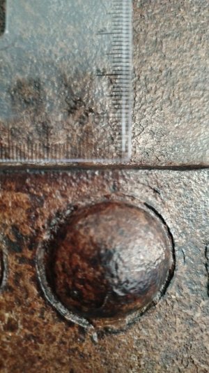
The history dimension: In Ship Building they started with round heads (SS Great Britain) everywhere, but changed to a flathead riveting method under the waterline on ships, to reduce drag at some point in time. I would estimate that started around 1900. In that case rivets are only visible by the little ring indentation around the rivet. That was because the metal was drilled to form a rivet countersink - and the rivet filled it out flush on the outside, but not to the very edge. That left this distinctive, well visible ring.
You can see that in detail on the picture of the salvaged german U1 submarine (a very early example built in 1906) in wikipedia:
https://de.wikipedia.org/wiki/U_1_(U-Boot,_1906)#/media/Datei:U1-Gesamtansicht_vom_Heck_her.JPG
It has to be mentioned, that spectators nowadays expect the big round head rivets on old steel structures, because they were used in public visible construction extensively (Eiffel Tower, Bridges...). So many German CVII U-Boat Models get covered with round rivet heads. But if you look at old HiRes photographs, the outer shell was almost completely flush. The most visible things are the welding lines of the side mounted tanks and the very small round head rivets for the shell plating on deck and the side plates. You can't make countersink on a rather thin material. These should be more like 0.1 mm (0.004 inch) in diameter.
So for U-Boats: high number of small rivets for thin shell plating, thick material together: the big flush rivets or the big round head rivets - often in details where the flush method could not be used, like negative round shapes. Also common in U-Boat building in WW2: mostly welded, but partly still riveted.
