• Win a Free Custom Engraved Brass Coin!!!
    As a way to introduce our brass coins to the community, we will raffle off a free coin during the month of August. Follow link ABOVE for instructions for entering.

Iron/Steel plates and rivets

Joined
Sep 17, 2018
Messages
806
Points
353

Location
Berlin/Germany
DETAILLING MATTERS

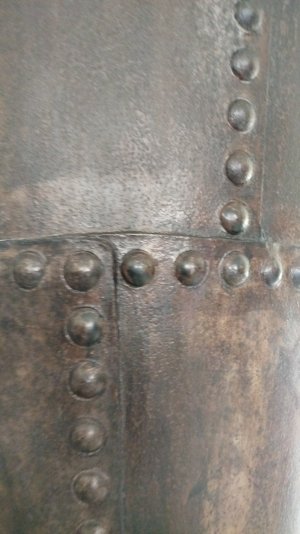
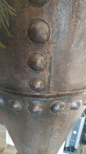
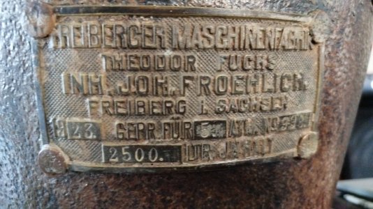
For all of us looking foreward to deal with rivited iron/steel in a bigger scale here an example of a original cylindrical hopper from 1923 built in a Saxonian iron works factory:
IMG-20250924-WA0011.jpeg

IMG-20250924-WA0003.jpeg
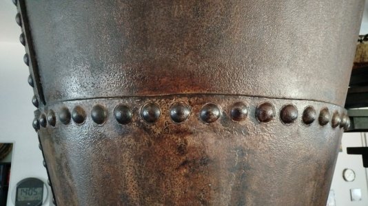
The plate joining in frontside view clearly shows the inregular edges of the plates:
IMG-20250924-WA0004.jpeg
An upside view to the joinings of three plates:
IMG-20250924-WA0005.jpeg
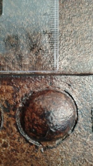
The scale of these rivets in millimeters:
IMG_20250924_141633_771.jpg
Hope this helps to end into the faith of todays' standards of exact edges and so on - it is craftmenship's work without laserguided CNC-accuracy.

Hth, C-H
 
I am building a model of a Great Lakes Freighter with a riveted steel hull. There are still a few ships sailing here on the Lakes that have partially riveted hulls. Following hull failures of all welded Liberty Ships in World War II, naval architects reverted to incorporating a few riveted seams in the hulls of otherwise welded vessels since cracks did not propagate across a riveted seam. Advances in welding and steel making technology have made this practice unnecessary. Fraser Shipbuilding located here in the Duluth Harbor still is able to repair these riveted hull seams. They were also hired by forensic Naval Architects investigating the Titanic wreck to make riveted test panels for destructive testing.

The rivets posted in the photo above are NOT the type that were used to fabricate ship hulls. The rivets shown above are called Snap Rivets. These were used to fabricate relatively light gage steel in above water locations; smoke stacks, ventilators, superstructure etc. The prominent dome shaped heads were formed with special dies.

Ship hull plating was fabricated with Pan Head rivets. These had a large cylindrical head with a trapezoidal cross section on one end. The other end called the “point” was plain. The entire rivet was heated in a forge. Placed in the hole, the end with the head was held tight while the point was closed up (hammered). Done properly, the closed up end was nearly flush with the shell plating of the hull. A large buildup of metal would have been removed with a cold chisel. Without getting into the structural mechanics, the huge holding power of these pan head rivets, was based on a different principle than the Snap Head rivets.

Rivets joining shell plating in a ship’s hull would be invisible at most scale viewing distances. In no case would they look like the die formed Snap Head rivets.

Roger
 
What Roger just said. Moreover, at the scale viewing distances of most all model scales, the edges of the plates would be straight and fair to begin with and much thicker than the example pictured.
 
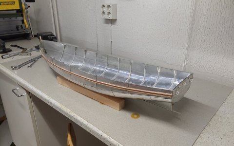
In a few recently made models I have tried to imitate riveted metal plates by covering the hull with plates made of soft 0.2 mm aluminium foil where riveting is pressed using a tool made of suitable gear.

20250313_083046.jpg
 
If I may ask, what is the approximate average diameter of a visible hull rivet head. I’m working on super-detailing a 1/200 U-boat and from eyeball proportions those appear to be in the 1 to 2 inch range. Am I close??
 
You are close!

The DIN (Deutshe Industrie Norm) regarding rivet definitions seems to go up to 36 mm - 1.4 inch. This is also the size I remember from the Rivets of the steel roof structure of the "Wiener Rathaus", where we had to do some few 100 rivet replacements. Spacing seems to have varied from one to two head diameters in between. So in your case in 1:200 that would be 0.2 mm Head diamenter and 0.2 to 0.4 mm (0.008 to 0.016 inch) spacing. For thicker material they used these big ones, for thin material (like turret housing, tank covers) half the head size with spacing close for high strength or with four heads distance for normal mounting of plates. (as it didn't have to be perfectly watertight and would have cracked the thin metal)

The history dimension: In Ship Building they started with round heads (SS Great Britain) everywhere, but changed to a flathead riveting method under the waterline on ships, to reduce drag at some point in time. I would estimate that started around 1900. In that case rivets are only visible by the little ring indentation around the rivet. That was because the metal was drilled to form a rivet countersink - and the rivet filled it out flush on the outside, but not to the very edge. That left this distinctive, well visible ring.
You can see that in detail on the picture of the salvaged german U1 submarine (a very early example built in 1906) in wikipedia: https://de.wikipedia.org/wiki/U_1_(U-Boot,_1906)#/media/Datei:U1-Gesamtansicht_vom_Heck_her.JPG

It has to be mentioned, that spectators nowadays expect the big round head rivets on old steel structures, because they were used in public visible construction extensively (Eiffel Tower, Bridges...). So many German CVII U-Boat Models get covered with round rivet heads. But if you look at old HiRes photographs, the outer shell was almost completely flush. The most visible things are the welding lines of the side mounted tanks and the very small round head rivets for the shell plating on deck and the side plates. You can't make countersink on a rather thin material. These should be more like 0.1 mm (0.004 inch) in diameter.

So for U-Boats: high number of small rivets for thin shell plating, thick material together: the big flush rivets or the big round head rivets - often in details where the flush method could not be used, like negative round shapes. Also common in U-Boat building in WW2: mostly welded, but partly still riveted.
 
Last edited:
You are close!

The DIN (Deutshe Industrie Norm) regarding rivet definitions seems to go up to 36 mm - 1.4 inch. This is also the size I remember from the Rivets of the steel roof structure of the "Wiener Rathaus", where we had to do some few 100 rivet replacements. Spacing seems to have varied from one to two head diameters in between. So in your case in 1:200 that would be 0.2 mm Head diamenter and 0.2 to 0.4 mm (0.008 to 0.016 inch) spacing. For thicker material they used these big ones, for thin material (like turret housing, tank covers) half the head size with spacing close for high strength or with four heads distance for normal mounting of plates. (as it didn't have to be perfectly watertight and would have cracked the thin metal)

The history dimension: In Ship Building they started with round heads (SS Great Britain) everywhere, but changed to a flathead riveting method under the waterline on ships, to reduce drag at some point in time. I would estimate that started around 1900. In that case rivets are only visible by the little ring indentation around the rivet. That was because the metal was drilled to form a rivet countersink - and the rivet filled it out flush on the outside, but not to the very edge. That left this distinctive, well visible ring.
You can see that in detail on the picture of the salvaged german U1 submarine (a very early example built in 1906) in wikipedia: https://de.wikipedia.org/wiki/U_1_(U-Boot,_1906)#/media/Datei:U1-Gesamtansicht_vom_Heck_her.JPG

It has to be mentioned, that spectators nowadays expect the big round head rivets on old steel structures, because they were used in public visible construction extensively (Eiffel Tower, Bridges...). So many German CVII U-Boat Models get covered with round rivet heads. But if you look at old HiRes photographs, the outer shell was almost completely flush. The most visible things are the welding lines of the side mounted tanks and the very small round head rivets for the shell plating on deck and the side plates. You can't make countersink on a rather thin material. These should be more like 0.1 mm (0.004 inch) in diameter.

So for U-Boats: high number of small rivets for thin shell plating, thick material together: the big flush rivets or the big round head rivets - often in details where the flush method could not be used, like negative round shapes. Also common in U-Boat building in WW2: mostly welded, but partly still riveted.
This is great information. Thank you very much!!
 
Back
Top