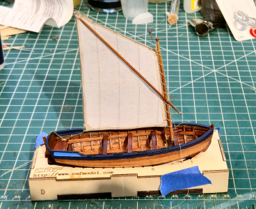
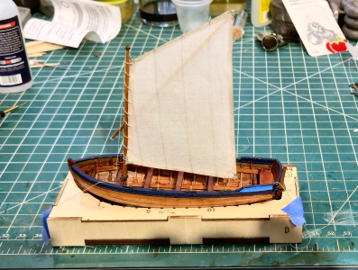
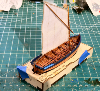
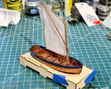
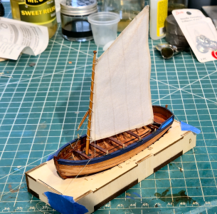
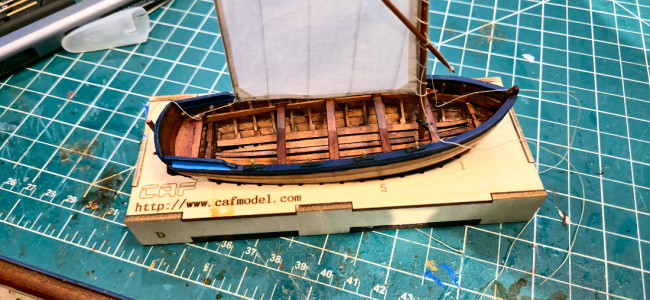
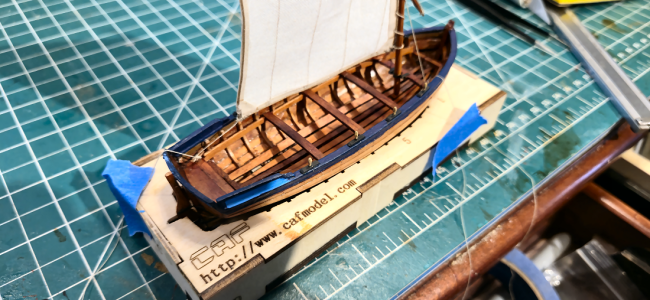
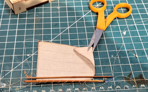
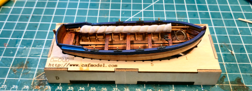
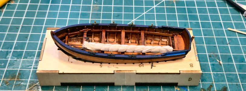
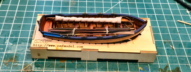
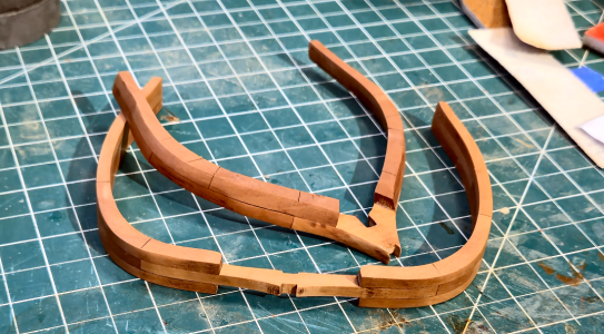
, enough of me screwing around and not working on the subject of this thread, the CAF 1/36 Scale La Belle. CAF had done a 1/48 scale version of this vessel that has been done quite often. I don't envy those modelers; even the 1/36 scale will be a challenge to me in many ways. An Italian outfit made a 1/36 scale version, which appeared to be a group build on a German modeling site, and they are darn well incredible, as it was a great kit to start with. But no longer available, so I'm happy CAF has gone with this model.
I'll start by comparing the mid-section frame of the model with Boudroit's drawings included with his La Bell monograph:
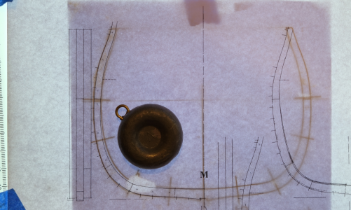
Boudroit's drawing is on top, and includes for reference the plank locations. The kit drawing is below, showing cross-lines where joints are located. The other outline is quite close, with very slight variations in a couple areas. Probably within my sanding and shaping ability. The inner outline is thicker toward the bottom, but I'm happy about that, as it makes it stronger, and if I /really/ wanted it closer to the monograph, I could sand that area more.
(BTW, I know there has been a lot of discussion and research concerning problems with Boudroit's drawings and analysis of the actual, or theorized, shape of the hull. I don't want to get into that here. The small variations between the various versions will not, IMHO, be visible in the model. I will ignore Boudroit's information where I have specific information to the contrary, and will explain why. But the niceties of the hull shape will be beyond the scope of this build. Hopefully.)
I'm going to take the process of building a couple frames tiny-step-by-step, as I think/hope there are a couple details and other information that may help others. Obviously, I won't do this for the remaining frames. I decided to start with the M section frame, the only triple frame on the ship and located at the broadest portion of the hull, and a severely beveled frame #2, to see how that works out.
Anyone who has built a Plank-On-Frame (POF) ship model is familiar with this process, but to help readers who may not have built one, I'm including this detail. The first step is, for each of the 28 built-up frames, to determine which parts are required, and where they go. The manual included with the kit includes diagrams of each laser-cut board with its part, to help in this:
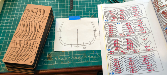
The needed parts for one frame are removed from each sheet. In the past, I've marked the part numbers beside each part, but so far I'm not doing that, partly because there's little room here to do it clearly. I do quadruple-check I have the right parts for each frame - the parts from adjacent frames are extremely similar, so this can easily happen. I've seen others write numbers on each part, but I don't like to do that. At least most of the time.
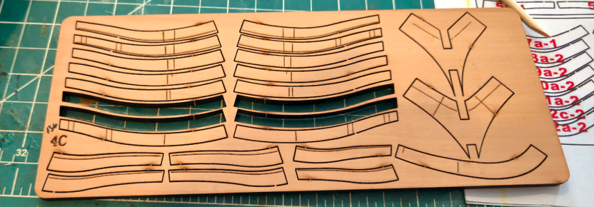
While looking at the various parts of the frames, and when comparing them to the frame outlines, you will find some lines that don't make sense, and seem like they shouldn't be there, like those circled below:
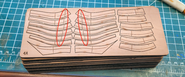
It turns out that they shouldn't be there. According to Tom, they are a "legacy from a previous version". That's kind of unfortunate, if you want to see the sides of the frames in your build, so you may have some extra sanding to do.
So, next I take the pieces for my frames, and place them in the approximate location to confirm that's where they go. I broke my rule of doing one frame at a time here, as I felt I was safe with the completely different frames being worked on:
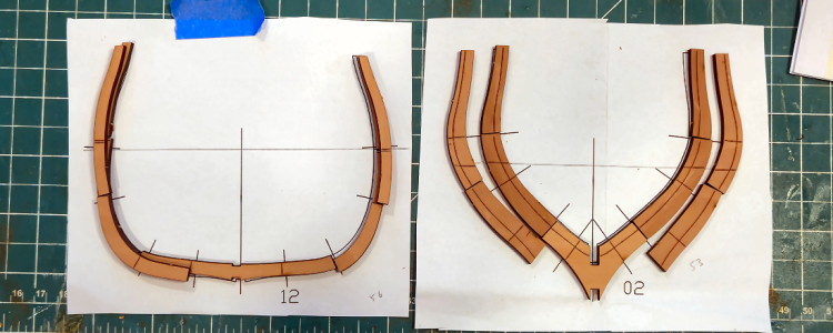
Most frame parts of laser-etched lines on one side, like the center portion below:
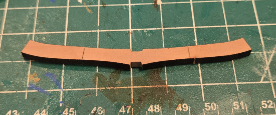
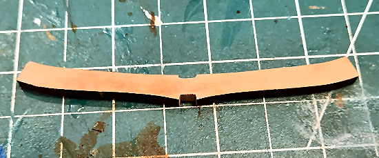
The "cross lines" I'll call them show the location of parts of the second frame, which overlap each other for strength a bit like a row of bricks. It's hard to tell from the photos below, but the notches are a bit narrow for the 4mm keel:
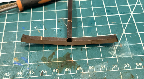
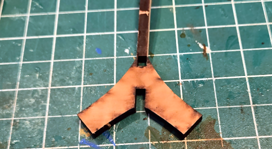
The notches are smaller than 4mm by less than 1mm, probably closer to 0.5mm. That seems a tiny amount, and it is, but 1) It's a lot more than is required to remove the char (and it's debatable if when gluing notches and parts such as this that the char needs removed at all), and 2) That 0.5mm, or whatever, is much more of a pain to remove than it appears to be (and should be).
I guess I'm not as skilled as most, and maybe a bit more impatient, but I've used about a dozen files of various styles, grits and shapes to widen this slot, while 1) Keeping the slot from being too wide, 2) Keeping the slot centered, by not removing more material to one side than the other, 3) Trying to NOT deepen the slot by more than the char, and 4) keeping the bottom slot corners sharp so the 4mm pieces fit in as far as necessarly.
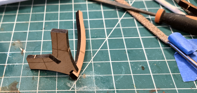
Sure, that's a common task for us model ship builders, and basically a simple one, but hard to get "just right". My first notch looks like this:
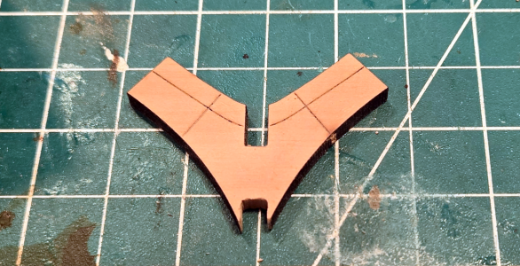
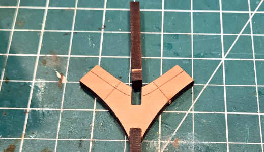
Yeah, it works, the part fits, and it will glue fine. But it's not neat. One side's a bit deep, and it's, well, ugly. Perhaps others have found ways of increasing the width of these slots, but I've not found a great one. This is the best way I've found to increase the width, without increasing the depth, which can more easily be done afterwards:
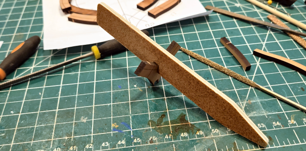
OF course, it depends on the state of the grit of each side being the same, but hopefully it is.
Again, why the big deal? Well, for just this frame Section 1 of La Belle, just counting notches involving the 29 frames, I need to make 116 notches, counting those in the keel and keelson. And, IMHO, there is no reason we should have to do this. Other notches, like those on the building frame, push together with little force and clearance without the touch of a file or sandpaper. The 0.5mm or whatever is allowed for this should not be there, for this location or any area where a known thickness piece (like 4mm for the frames) is inserted. The 4mm pieces are accurate within less than 0.1mm, most much less. The "normal" 0.5mm allowance for pieces like the frame outlines themselves should /not/ be necessary on the notches.
Tom - I know you're following - please consider allowing far less, maybe close to zero, clearance in laser cut notches when known thickness boards are inserted into them. Sure, the outline of parts needs the allowance, but not the notches.
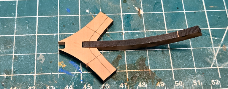
Anyhow, after filing, sanding or whatever method (I considered buying a 4mm wide file, but couldn't find one, only a round one) the notch, the 4mm thick piece hopefully fits well and is of the correct depth:
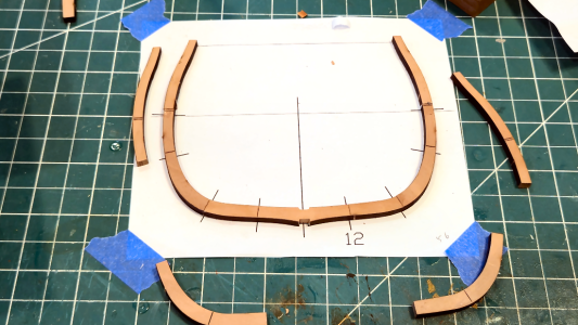
After the ends of each piece are lightly sanded, they are positioned on the paper template using Fixo-Gum rubber cement to cement the pieces to the paper, and white glue to glue them to each other. As this is a triple frame, I can place the center frame with the laser lines pointed up.
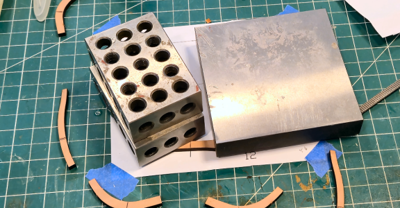
Weights hold the pieces straight while the glue dries. I've used a piece of glass to mount frame pieces on in the past, but think my work area is level enough for this purpose.
After the glue of the first layer dries, I can add the second layer. The laser lines on the center piece are somewhat useful here, but all I really need is where the pieces start. I've found that excessive sanding for end-mating parts isn't really necessary, and can sometimes result in a shorter frame than desired. I prefer all the frames as high as possible, so I can be sure of obtaining the correct height.
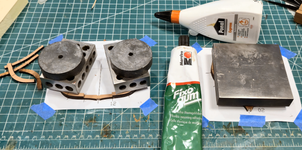
So now there are two layers with one to go:
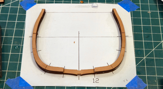
At this point, the center frame can be removed from the paper to add the 3rd layer:
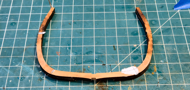
Any Fixo-Gum can easily be rubbed off, any paper sticking is caused by the white glue, so a light sanding eliminates those items and provides a level surface for gluing the next layer. The template can't really be used for that, but isn't necessary, as you're just matching the parts to the existing structure. I started at the top, actually.
Frame #32, and all the frames /except/ number 12, the triple frame, are double frames so the initial procedure is a bit different. Most frames, in addition to the (unnecessary) cross lines, have lines that show where bevels are to be cut/sanded. TO be sure they will be visible when the frame is done, the frame pieces have to be placed on the paper with the laser-cut side down.
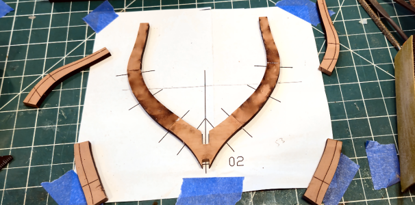
My single plate weight works well here for this smaller frame:
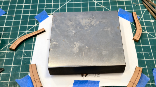
After the glue is dry, the second layer can be glued to the first:
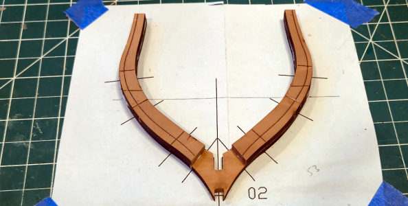
Above is a good photo that shows the cross lines on the pieces. I don't feel they're required because the lines on the paper show exactly where things go. IMHO those are NOT necessary, and are just something that should be removed if visible on the finished model. Of course, the contour lines have to be included, because they indicate bevel locations.
Tom - Please consider eliminating the cross lines, as the aren't really required when using the paper templates.
After the glue is dry, the frame is removed from the paper:
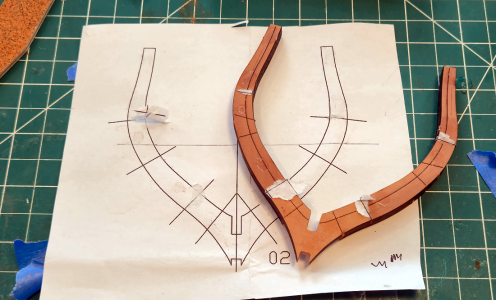
Next I sanded the contours in frame #2 above. (The triple frame above has no lines or contour, so that's not required there)
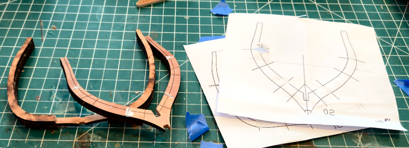
I also removed the char and sanded the inner and outer surfaces of the two frames. I feel the inner contour will be close enough visually and construction-wise and this will eliminate inner sanding in place, which is difficult. I've also sanded the outside of the frames. After assembly, they can be recontoured, if necessary, but if that isn't required, they'll have been sanded with the grain, and have an initial finish coat.
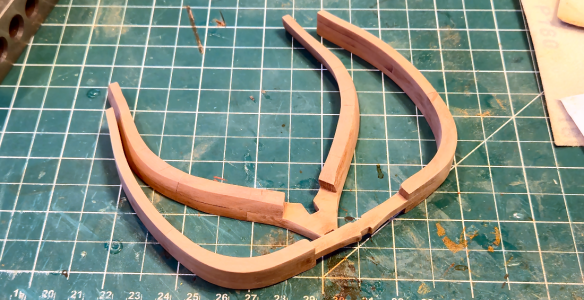
And after a coat of finish: - Whoops, it seems there's a limit of 25 pics, so I'll finish this post and put it in another one.