• Ships of Scale has incorportated an extra level of security when you log In. Please follow on-screen prompts to acknowledge that you are not a robot via a "Check Box" or a "Pictorial Check Box Puzzle". This is needed due to higher level of AI Activity Security.
  • SUBSCRIBE TO SHIPS IN SCALE TODAY!

    The beloved Ships in Scale Magazine is back and charting a new course for 2026!
    Discover new skills, new techniques, and new inspirations in every issue.

    NOTE THAT OUR NEXT ISSUE WILL BE July/August 2026
  • Win a Free Custom Engraved Brass Coin!!!
    As a way to introduce our brass coins to the community, we will raffle off a free coin during the month of August. Follow link ABOVE for instructions for entering.

Le Requin-Zebec-1750 POF 1:48 (ZHL)

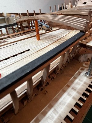
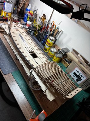
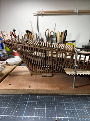
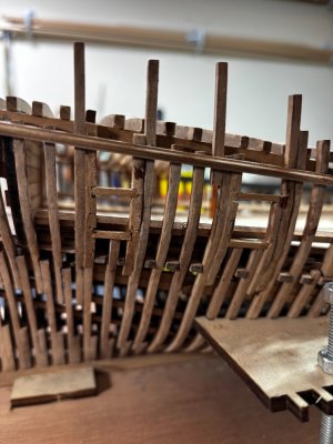
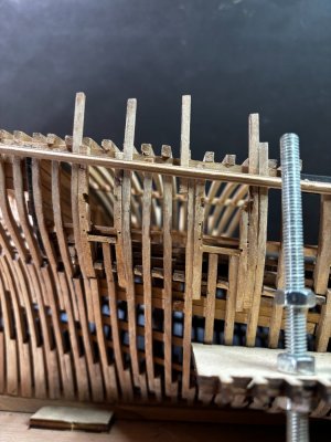
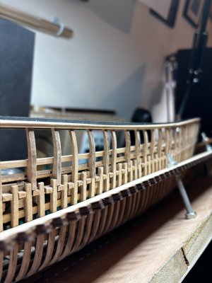
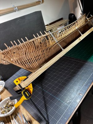
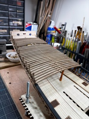
In this post I wanted to display elements on the ships main rail. It seems to me I have to spend more time analyzing the plans and notes, then converting to English than actually building the ship. I've been telling myself all future builds, plans and commentary need to be in English!

After setting the port side it became necessary to level the main build board in the transverse direction allowing me to level over to set the rail elements for the starboard side. Check it out.

View attachment 626659View attachment 626660View attachment 626661View attachment 626662View attachment 626663View attachment 626664View attachment 626665

Its Friday! Have a great weekend all.
Till next time, thanks for checking in.
A challenge to get a flowing curve neat over such a long distance, Daniel. And to get both sides equal. It is remarkable to see that two frame ends consistently terminate on the inside of the outer rail, with a third underneath. And ‘the doubles’ then become locked by the inner rail. The assembly of the three rail parts then forms a beautiful combined rail. (If I saw it all correctly ;)).
I went back till pag. 29 of your log when you started installing those frame extensions and now I understand more and more the challenges you got during the build of both sides above the deck.
Regards, Peter
 
A challenge to get a flowing curve neat over such a long distance, Daniel. And to get both sides equal. It is remarkable to see that two frame ends consistently terminate on the inside of the outer rail, with a third underneath. And ‘the doubles’ then become locked by the inner rail. The assembly of the three rail parts then forms a beautiful combined rail. (If I saw it all correctly ;)).
I went back till pag. 29 of your log when you started installing those frame extensions and now I understand more and more the challenges you got during the build of both sides above the deck.
Regards, Peter
Thank you for your observations, Peter. In your comment ("If I saw it all correctly") I believe your referring to the frame ends as doubles which they are, but I had mislabeled them as frame extensions. They are really called standards (which frame each side of a canon port opening and sit on top of the main deck) combined with the frame extensions that originate from the keel, form the skeleton of the bulwarks.
 
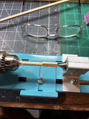
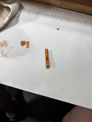
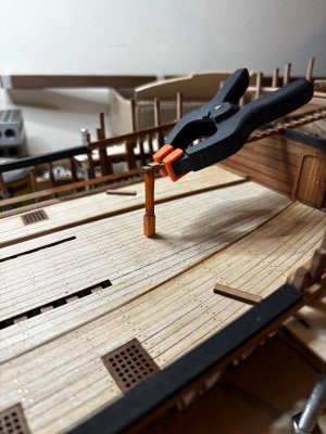
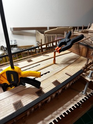
A fun little bid of woodworking in the miniature world. In preparation for the upper deck crossbeams I have set the backbone support, attached it to the cabin bulkhead and the stern post backing. Next, I needed a column to support the cantilevered portion beyond the cabin bulkhead. The plans just show a simple square post with honed corners, but I decided to be a little fancier using my small lathe and configure a nicer column. Check it out.

IMG_1988.jpegIMG_1989.jpegIMG_1990.jpegIMG_1991.jpeg

I also finished the main rail on the starboard side with the exception of special conditions at the bow section on both sides. The upper deck will also have a railing component.

Thanks for checking in.
Till next time.
 
A fun little bid of woodworking in the miniature world. In preparation for the upper deck crossbeams I have set the backbone support, attached it to the cabin bulkhead and the stern post backing. Next, I needed a column to support the cantilevered portion beyond the cabin bulkhead. The plans just show a simple square post with honed corners, but I decided to be a little fancier using my small lathe and configure a nicer column. Check it out.

View attachment 628433View attachment 628434View attachment 628435View attachment 628436

I also finished the main rail on the starboard side with the exception of special conditions at the bow section on both sides. The upper deck will also have a railing component.

Thanks for checking in.
Till next time.
Dear Daniel
the backbone support, came out great
 
A fun little bid of woodworking in the miniature world. In preparation for the upper deck crossbeams I have set the backbone support, attached it to the cabin bulkhead and the stern post backing. Next, I needed a column to support the cantilevered portion beyond the cabin bulkhead. The plans just show a simple square post with honed corners, but I decided to be a little fancier using my small lathe and configure a nicer column. Check it out.

View attachment 628433View attachment 628434View attachment 628435View attachment 628436

I also finished the main rail on the starboard side with the exception of special conditions at the bow section on both sides. The upper deck will also have a railing component.

Thanks for checking in.
Till next time.
That then gives the satisfaction of making it from scratch, Daniel. A nice support with nice details.
Regards, Peter
 
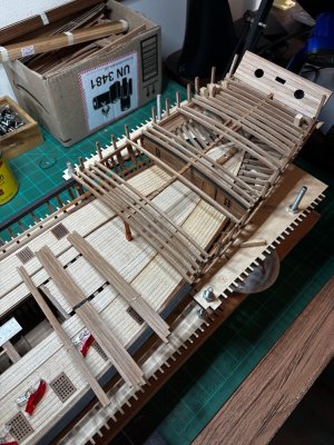
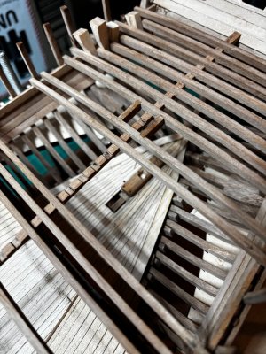
I'm making good progress on the upper deck construction. After setting the rest of the deck support beams, I can start laying the deck boards. You may notice I just set a few wall planks in the cabin area before closing it off with the deck support beams, since I will be completely enclosing the cabin area with no observation openings built in, for me there is no point in finishing this area out and I'm happy to keep moving on. I provided a couple of carlings in the deck opening for the mizzen mast to penetrate. Once I set all the beams, I can remove the small section of the center deck beam support (backbone) that will be bounded by the carlings to form the opening. You can see the mast step below.

IMG_1994.jpegIMG_1995.jpeg

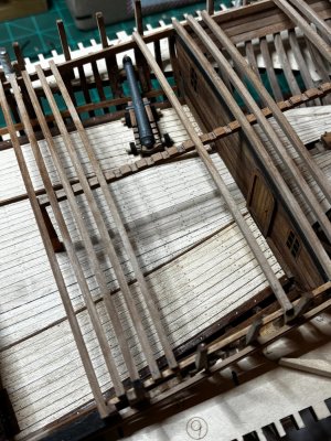
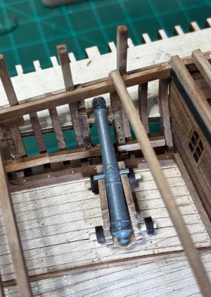
The covered open area forward of the cabin wall is 10 centimeters in length and 2 canons on each side will be placed under the covering. It dawned on me to predrill for the canon wall anchoring system (bolts and rings) while I still had good access.

IMG_1997.jpegIMG_1998.jpeg

Hope you all enjoy this. Till next time, thanks for looking in.

IMG_1999.jpeg
 
Now that I have all the upper deck floor beams in place, I need to clean up the 4ea. canon port opening framework that lies underneath the upper deck overhang. I'm not quite ready to set the upper deck floor planks as I want to be sure I have the 4 canon port openings location squared away and I can do some manipulations from above if necessary. Apparently, my ability to follow directions in the early stages of frame setting leave much to be desired as I shouldn't need to do this but nevertheless adjustment is needed.

I was able to remove the aft jig framework to work in this area, the first two pictures show the framework in place then after removal which really opened up this area.

IMG_2003.jpegIMG_2005.jpeg

Next, you can see where I began removing some of the port framing elements in preparation for proper placement according to the actual canon mockup I made.

IMG_2007.jpegIMG_2010.jpeg

Again, I can hardly wait to cover up this pearwood.
I set the build board up on an angle for better access as I have a lot of trimming and pre fairing to do.

IMG_2011.jpegIMG_2012.jpeg

I sure thank you all for looking in and welcome any comments or suggetsions.

IMG_2006.jpeg
 
Back
Top