• Ships of Scale has incorportated an extra level of security when you log In. Please follow on-screen prompts to acknowledge that you are not a robot via a "Check Box" or a "Pictorial Check Box Puzzle". This is needed due to higher level of AI Activity Security.
  • SUBSCRIBE TO SHIPS IN SCALE TODAY!

    The beloved Ships in Scale Magazine is back and charting a new course for 2026!
    Discover new skills, new techniques, and new inspirations in every issue.

    NOTE THAT OUR NEXT ISSUE WILL BE July/August 2026
  • Win a Free Custom Engraved Brass Coin!!!
    As a way to introduce our brass coins to the community, we will raffle off a free coin during the month of August. Follow link ABOVE for instructions for entering.

New design Le Saint Philippe -1693 - 1:48 by Trident Model Update 0926

Hi everyone,
This has been a really interesting discussion to follow — thank you both.
I think for my purposes, I will just build what Lemineur's drawings show. If the frames have a slight forward rake in the offsets, I will follow that; if I find during modeling that they are closer to square to the keel, that is what I will use. Either way, this thread has made me look at the body plan much more carefully than I would have otherwise.
Thanks again to both of you for the input.
Cheers,
Trident
 
Well, what’s interesting, Paul, is that I think I remember Nigel grappling with this issue quite a long time ago. I must confess that I have not dug up the SP monograph from where I keep it, but I trust what you are saying about the drawings is true.

However, from a practical standpoint, on the slipway, it would seem remarkably difficult to maintain a uniform forward cant. As far as I understand it, if what the shipwrights at Gravelines are doing with the Jean Bart reconstruction is credible (https://espacetourville.com/actus/tourville-actualite-n11-avril-2026/), the frames are raised in futtocks from the floors, on up.

The stem, sternpost and fashion pieces are erected first, and the hull rises from the floors. That said, there is additional confusion in models I have seen that purport to demonstrate shipyard practice. In this scenario, you have stem/stern/fashion pieces erected, as well as the full mid-ship flat frames, and the two full quarter frames, for and aft. Upon this minimal skeleton, ribands are attached to show the fair run of the hull. Any necessary adjustments can be made, before filling-in the fore and aft runs of frames.

Even in this scenario, I would think that in the 17th C., builders would have quite a challenging time avoiding cumulative error in their forward cant, unless the dead-flat section of framing is a sufficiently solid enough reference to extend the cant fore and aft.

As quite a number of the First Marine French builders (1660’s through 1680’s) were Dutch trained, it seems more likely that their ships rose from the keel.
Thanks for this, Marc.

It subtly raises the question of whether what is designed can actually be built. Of course, I enter into this conversation with all the knowledge of 17th century naval architecture I obtained during my postdoctoral work in orthodontics and Christian theology (that is: none Redface), so I cannot speak intelligently on the practice of shipbuilding. Still, I kind of feel like they could have built anything they wanted...

As a modeler I did not attempt to reproduce actual practice. I simply raised the keel up 1.2 degrees and erected the fully built frames perpendicular to the build board. Things only got dicey as I approached the stern as the frames now begin to tip in the other direction and are no longer parallel.

@Trident Model you have been very patient as we have caused this little departure from your impressive work report. Thread drift can be frustrating - though you seem to be taking it in stride. My respect.

I only wish you had started this project two years ago ROTF. Oh, and I'm also annoyed that you speak English better than I do!
 
Hi everyone,
This has been a really interesting discussion to follow — thank you both.
I think for my purposes, I will just build what Lemineur's drawings show. If the frames have a slight forward rake in the offsets, I will follow that; if I find during modeling that they are closer to square to the keel, that is what I will use. Either way, this thread has made me look at the body plan much more carefully than I would have otherwise.
Thanks again to both of you for the input.
Cheers,
Trident

In my humble opinion, the answer to this interesting question lies in how these large ship were built in XVII french shipyards, figure I suppose is known or presumable at least. In a dry dock scenario, had the frames obviously laid down via a pumb bob, frames could be easily made orthogonal to the centre line. In a sloped slipway hypothesis (less likely, to me), frames must have been canted forward a bit instead, maybe resulting in some more or less vertical layout of the axial carpentry to the waterline. Just picture the cutter as the extreme case.
 
Last edited:
Great question! For ships of this era, all frames are built perpendicular to the keel as the primary reference. The 2–3 foot difference between fore and aft displacement creates hull trim, so the frames are naturally not square to the waterline. That is how the original lines plan defines the framing.
Hi, if you do a thorough search on axial shipbuilding, you'll see that the frames are positioned perpendicular to the base line and the waterline. The keel is never at the same level as the base line; the base line and the construction line are not parallel. Frank
 
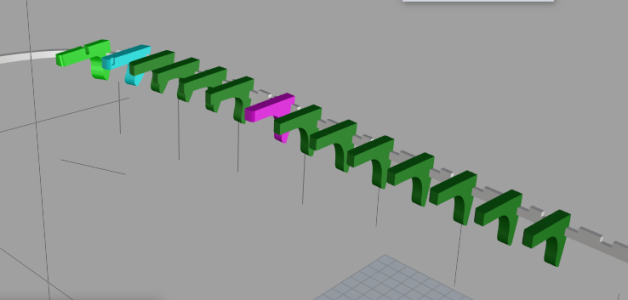
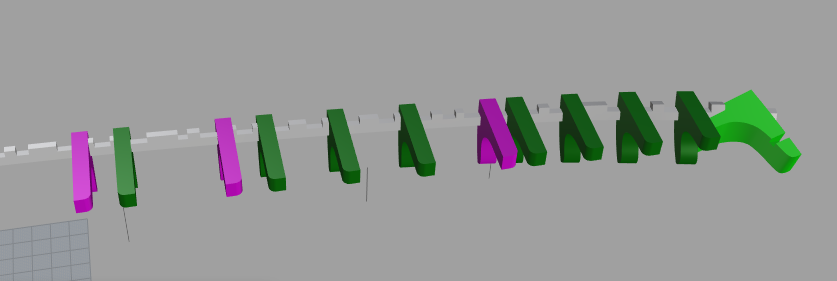
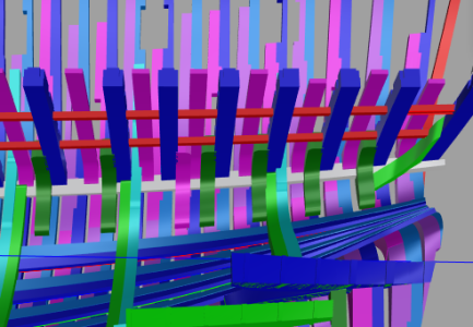
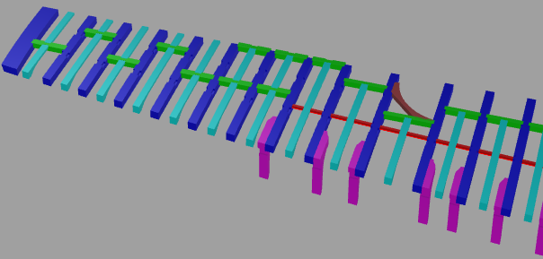
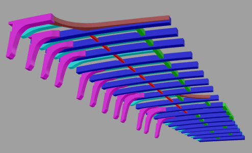
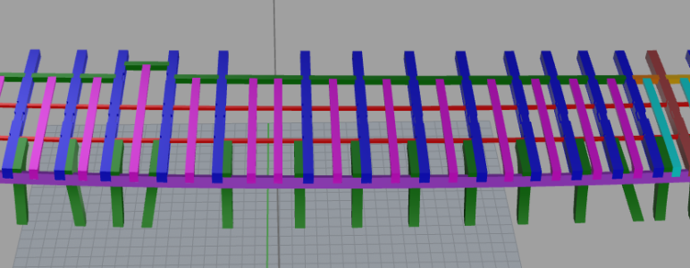
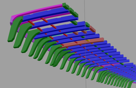
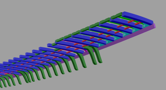
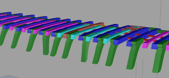
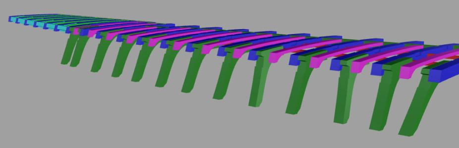
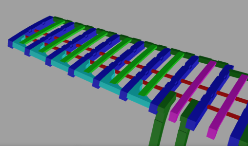
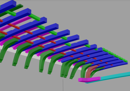
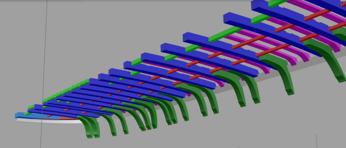
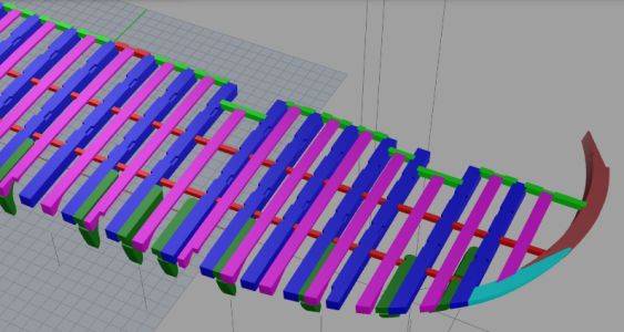
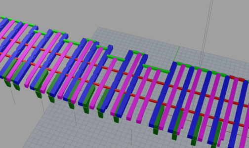
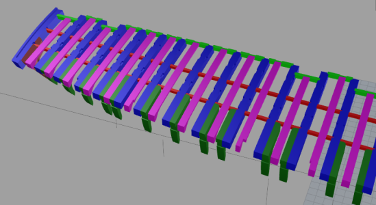
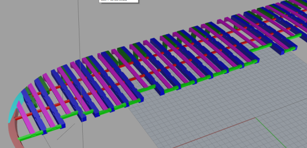
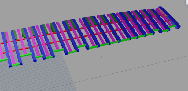
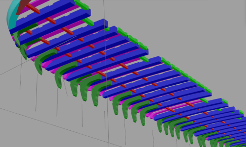
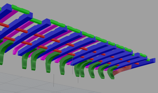
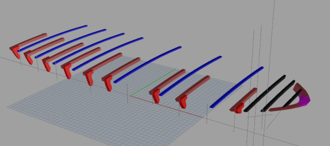
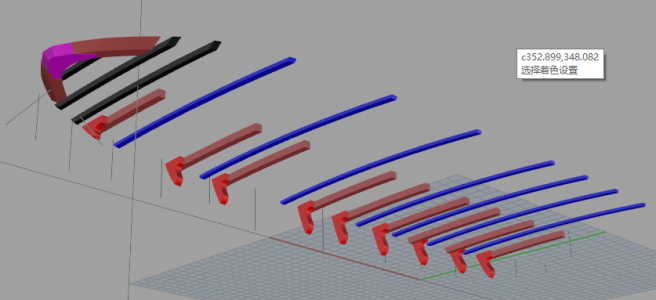
Hello everyone.I adjusted the position of some beams according to the futtock locations. The modifications are only a fraction of a millimetre, nearly impossible to see in photos, so I will not post separate pictures for this change. This update mainly shows the beam knees for the third gun deck.

1.png

2.png

3.png

4.png

5.png

6.png

7.png
 
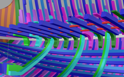
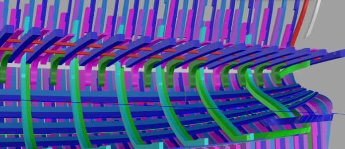
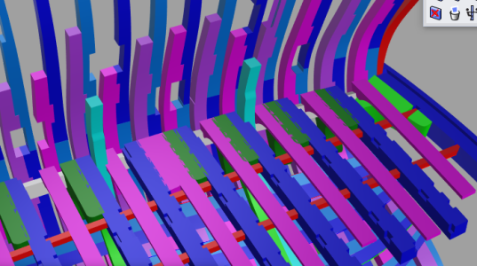
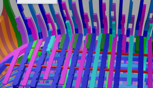
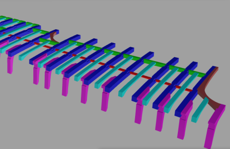
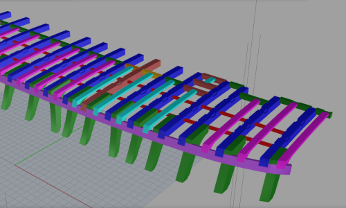
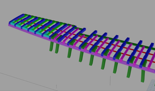
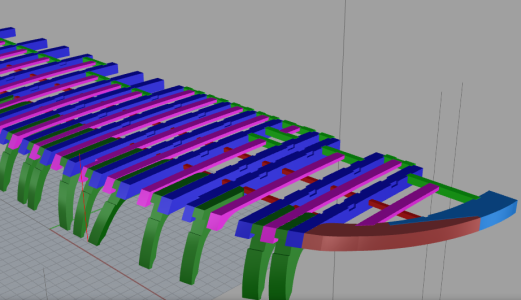
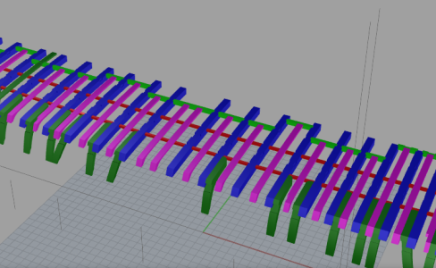
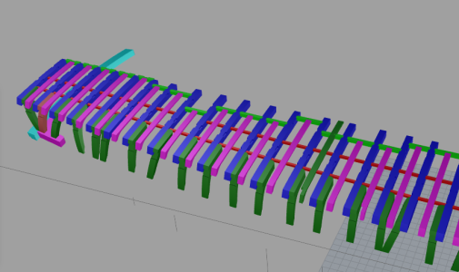
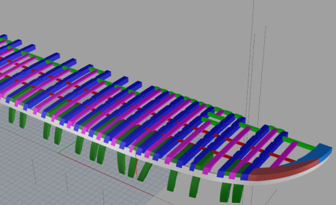
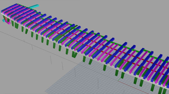
Hello everyone, this update covers the brackets on each deck, which I will present layer by layer.

The main hull structure has been completed. The design of the internal hull structure is temporarily on hold, and those details will be refined gradually at a later stage.

In October, I will focus on the design of the building berth and conduct feasibility verification for machining several distinctive components. Our new equipment is also expected to arrive in October.

Besides, there are two more fully designed models waiting for prototyping and validation. For this reason, less time will be allocated to the San Felipe project.

The update pace will not be as fast as it was in September, yet the project will not stall.

Thank you all for your continued interest and support for this project.
 
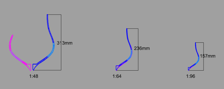
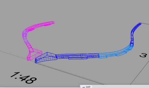
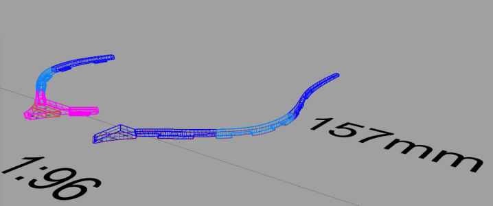
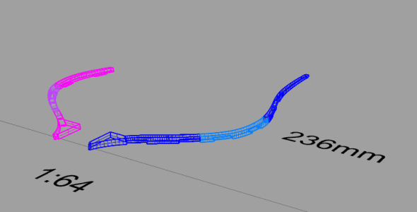
Hello everyone. We plan to carry out limit tests in the near future. The purpose is to verify the forming capability of the model while retaining design details and structural proportions, and record the corresponding machining time. If you are interested, feel free to let me know which scale you focus on. Thank you all for your support.

Test groups are listed below:

  • Scale 1:48, plate thickness: 6 mm, 7.5 mm
  • Scale 1:64, plate thickness: 4.5 mm, 5.5 mm
  • Scale 1:96, plate thickness: 3 mm, 4 mm

1.png

2.png

3.png

4.png
 
Back
Top