• LUCZORAMA SHIPWRECK SCAVENGER HUNT GIVEAWAY. 4 Weeks of Fun • 1 Legendary Prize ((OcCre’s Fram Ship)) • Global Crew Welcome!
    **VIEW THREAD HERE**

L'Orenoque Mamoli 1:100 scale

Finally, shipmates, what are your thoughts about the following:

Scuppers - there are no scuppers in the kit plans or the original plans. There would have been scuppers, right?

Paint scheme inboard - I was planning to use the natural wood color for the inboard bulwarks - If you look at the pictures of the models in Martin's posts and in Post 80 it looks like natural wood is the right call and everything else is black - or at least the trim is in black.

Treenails - nails - At this scale I have been thinking not to show treenails. Wouldn't they be so small as to be invisible? On the other hand it is a nifty detail.

Blessings. Peace. Gratitude.
Chuck
 
Good evening Chuck. Wow it is an adventure reading through your log. I had to play a little catch up. The thread relating to the cannons and Jerrys input and design is brilliant. I like your approach to making the bulkwalk higher this will work nicely and lastly lovely 1st layer planking.

Re your last post. My 2cents….at a 1:100 scale the amount of detail is always reduced and it becomes increasingly difficult to include this. Scuppers I think you should include while deck treenails would be too small to get realistic - IMHO).Paint or natural- natural.
Cheers Grant
Grant!

Thank you! First, I hope the knee is coming along!

You are too right about Jerry's input. I need to put him (among others :D) on retainer! I appreciate your appreciation! I'm glad I raised the bulwark height - the kit height is pure non-sense even without the gun problem. Frankly, for the rest of this build I'll be channeling my inner Grant Tyler/Pete Gutterman creativity, artists eye, problem solving with unique methods - you get it, right?

Thank you for your 2 cents! I agree with you entirely - except for there will be some paint ;)

Blessings. Peace. Gratitude.
Chuck
 
Ocean going boats often had "freeing-ports" which is basically a gunport for letting large volumes of water off the deck, while the "port-lid" kept water from coming in that way.
If you put pipe-scuppers in, make sure they aren't in the way of something, and nothing's in their way; don't have them discharge right over a gun-port or the boarding steps, directly behind a chain-plate, etc.
 
Hmmm ! Either you've been slightly ahead of your posts or i shall have to call you "four hand Chuck " as that's the quickest hull i think i've ever seen ! All the french blogs seem to think that stern is very awkward to plank so you have managed very well. There are no builds i have seen that even attempt to build with historical accuracy, they all appear to be straight out of the box, so you are headed towards a unique build that you can be proud of .
 
What ho, shipmates!

Here's the second planking and the bulwark heightening along with some deck planking. I know how some of you feel about painting your models :eek: :eek: :eek:
Personally I believe in paint where appropriate :cool:. I raise the issue because my 2nd planking is done to allow me to use the wood as a color at the level of the lower deck guns. For that reason, the planks are to scale for that region of the hull and above. Below that point, I decided that I could save some effort (takes time to cut the 1/8 x 3 inch planks, dress the edges and glue them on) because the lower part of the hull is meant to be painted black and will be coppered below the waterline.

Another thing. I like the way the variations in the wood look when oiled so the variations in color and grain are there on purpose. This applies to the "color band" to give the lower gun deck the Nelson checker, the inside of the bulwarks and the deck:)

In this pic look at the bow below the waterline:eek::eek::eek:ROTF I did the starboard side first to experiment with how the planks would run. Because L'Orenoque will be in the same room with Harriet Lane, and because Harriet Lane is displayed port side out - the port side is the money-maker. Not that anyone but you and my Admiral will know because this heresy will be covered in copper.

View attachment 531148
View attachment 531149

Here's the money-maker

View attachment 531147

And I was able to make the stern look more or less like the illustration in the plansROTF


View attachment 531146View attachment 531153

And now the bit with the pliers . . .View attachment 531152
I see that I have to post a reply more often …….. the day after my respond about the first layer, there is already the post of the second layer ….. ;). And starting with the deck planking. Well, Chuck, the outcome of the second layer looks very nice.
Regards, Peter
 
My $.002 with Grant's=.004.;)
That's a load of progress in record time!
I've never been able to pull off a hull that fast and with such nice results as quickly and efficiently or so pristinely in anywhere near the time! :D Thumbsup Thumbsup
Pete! Thank you! That 4 cents is wealth IMHO!

As to the speed - I went through a period where I just worked on the hull and didn't post. Hull planking is not the most interesting subject. I know I just offended someone ROTF Apologies, shipmates!

The first planking began on June 14 and was completed June 22. I finished the second planking on July 4. So, nothing speedy about it :). When I started to post about the hull the work was already done.


Blessings.
Chuck
 
Ocean going boats often had "freeing-ports" which is basically a gunport for letting large volumes of water off the deck, while the "port-lid" kept water from coming in that way.
If you put pipe-scuppers in, make sure they aren't in the way of something, and nothing's in their way; don't have them discharge right over a gun-port or the boarding steps, directly behind a chain-plate, etc.
Jerry! Thank you for this direction! I would certainly have put the scuppers in the wrong locations without it.

Next question: Do the scuppers sit in or above the waterways?

Blessings.
Chuck
 
Hmmm ! Either you've been slightly ahead of your posts or i shall have to call you "four hand Chuck " as that's the quickest hull i think i've ever seen ! All the french blogs seem to think that stern is very awkward to plank so you have managed very well. There are no builds i have seen that even attempt to build with historical accuracy, they all appear to be straight out of the box, so you are headed towards a unique build that you can be proud of .
Martin! If you look at my response to Pete's post you'll see how I worked the magic trick of appearing to have finished all of the planking in a couple of days:D

That's interesting to hear about the French modelers of this ship. Before I started on her, even before I bought her, I tried to find build logs. I only saw a couple and they did not show any of the details of their efforts. In fact, I found a British log where the builder was very excited about all of the deck structures and then very disappointed when he discovered that the kit was not a representation of the historical ship. Unfortunately, I could not see the pictures he posted of his build, but that log led me to find the actual plans and to discover the other print reference sources that helped me get my head around what L'Orenoque probably looked like. It took some time to do that research which I might not have done if I hadn't learned from my Harriet Lane build that the kit may not actually represent the ship as it was AND that the internet is a great resource for finding the actual plans. So, the work to discover the ship PLUS my shipmates have made all the difference.

You have been a marvelous resource in that regard. Thank you, Martin!!!!

Blessings.
Chuck
 
Hey Chuck,

that looks really good and the fact that you raised the bulwark was exactly right. Now the shapes and contours of the hull are just right. Great. Stick with it.......

Cheers Günther Ship-1
Gunther! Thank you for the compliment and encouragement! I agree with you! On the whole the side on profile looks pretty good. I was worried about distorting her appearance too much by adding 3/16" to the height of the ship. Honestly, I think the kit needs a major redesign which should start with modifying the bulkheads to lower the false deck by 3/16" - 1/4" so that the lines remain as designed.

Blessings.
Chuck
 
I see that I have to post a reply more often …….. the day after my respond about the first layer, there is already the post of the second layer ….. ;). And starting with the deck planking. Well, Chuck, the outcome of the second layer looks very nice.
Regards, Peter
Peter! Thank you for the compliment! As you now know, the process took more than 2 weeks. :D

Blessings.
Chuck
 
i have a question for you...how are the wheelhouses supported in the mamoli world ? I had decided on two crossbeams, fore and aft of the paddlewheels, and straight across the ship just below deck level for L'Aigle, but i can see no such structure for the moment ? Are there strengthening blocks built in behind the hull structure at these points ? Never having seen the Mamoli plans,I must admit that i am curious !
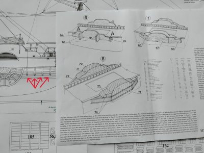
Martin! It took a bit longer than I intended to respond to your question about the wheel house construction in this kit. In this pic you'll see that the instructions have you glue the inboard side of the wheel house directly to the side of the ship. There is no instruction about the supports, only a plan view of a series of braces running from the bottom of the sponson deck to the hull (red arrows). If one built the kit as instructed :eek: :eek: :eek: there would be four of these braces aft of the paddle wheel and four forward of the paddle wheel. Of course. the kit plans are nonsense. Moreover, it has the builder adding the delicate paddle wheels after the wheel houses are aboard. UTTER NONSENSE!!!


LO Paddle Wheel House Kit Plan.jpg


In all of the images of these ships, the wheel house was not just slapped on the side of the ship. It is more likely that the wheel house structure rode on the bulwark and extended some distance out onto the deck. In fact, in the pictures you shared of the models of Sphinx, given what appear to be well researched models built to represent the real ship, one sees that the paddle wheel house did ride the bulwark extending onto the deck far enough to make room for a structure on deck that followed the contours of the paddle wheel house.

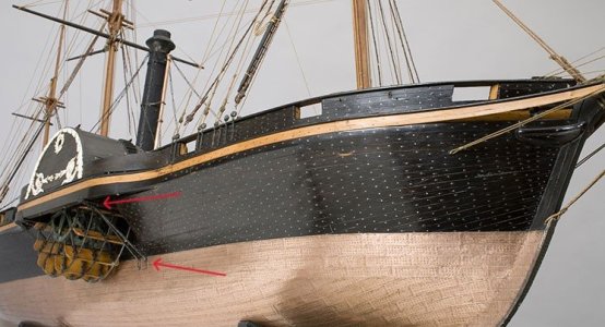
As you know, none of the actual plans for these ships show how the designers intended to support the weight of the wheel house outboard. The model of Meteor, however, does show that the wheel house on that ship had iron braces to help support the weight.

Meteor wheel house support.jpg

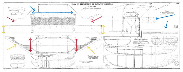
My plan is to build the structure in parts off of the ship. Since this is how the real ship was built, I'll do my best to replicate the plans for the bateaux tambours.
I see at least 4 major parts: 1 - Yellow arrows - the external wheel house sponson deck; 2 - Red arrows - the lower section of the external wheel house; 3 - Blue arrows - the bateaux tambours; and 4 - the inboard structure. I'll probably limit the number of braces - we'll see On the display side of the ship, I may even try to show the boat being readied for lowering - see upper right of the plan below.

boat stowage on paddlewheel box arrows.jpg

I'm fairly confident about the construction of the wheel houses - except for the boats themselves. Again, we'll see.

Blessings.
Chuck
 
Scuppers: There are many reasons why she would have had scuppers. A big one is what Naval Architect’s call the Free Surface Effect. Water is heavy (seawater, 64 lbs/cubic foot). If you multiply even a small depth of water by the deck area this adds up to a lot of weight. This deck load is dynamic. As the ship rolls, the water moves from side to side. This will negatively affect her transverse stability.

Although water would drain through gunports, this would still leave a significant amount of water trapped on the deck beneath the gun port sill. Scuppers would have been provided to drain this water.

Roger
Roger! Thank you for the explanation of the necessity of scuppers. I don't understand why kit designers of ocean-going vessels delete important details like scuppers. As you know from my Harriet Lane build, Webb's plans showed the darn things, but the kit had none. Here, the original plans don't show them, but still they must have been there. In any event I'm glad to know the why (from you) and the where (from Jerry @JerryTodd)!

Blessings.
Chuck
 
Jerry! Thank you for this direction! I would certainly have put the scuppers in the wrong locations without it.

Next question: Do the scuppers sit in or above the waterways?

Blessings.
Chuck
The "freeing ports" make a lot of sense and the begin to appear on American carriers in the 1850s. The MS "Flying Fish" plans show them, So I added them to my "Flying Cloud" (even though I haven't seen them on any plans) given that she and "Flying Fish" were built in overlapping succession. "Harriet Lane" might well have had them because she's a Wm. Webb ship with a clipper hull and (I believe) "Young America" had them. Webb built the "Harriet Lane" not long after "Young America". Scuppers were unlikely to keep up with a clipper hulled ship's deck awash in heavy seas. (IMHO)
 
Some things are "common," every ship has scuppers of some sort. Drawings may show them if the designer wants them in specific places, especially if the ship's a "new" type builders might not be accustomed to. When they're left off, the designer's basically trusting it to the builder to do what he's accustomed to. There's usually a set of instructions accompanying plans sent to builders citing details, standards, tolerances, etc; The so&so will be of white oak and no taller than such&such, so as to not interfere with the thing-a-ma-jig, otherwise, the so&so is to be of the usual height, and like that.

Don't forget the gun-deck will have it's own scuppers, much as the Constitution does, though I've seen them modeled as port-lights by mistake.

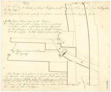
Here's a British view of scuppers for frigates and SOL's dated 1817
1752279365002.jpeg
As the scuppers on my Constellation need to be functional, I simply drilled through the waterway at 40°-ish, and epoxied in straight brass tube that I cut flush when it set up.
At 1:100, you could imply scuppers by impressing tube into the planking (remember the discharge end will be an oval), or just drill shallow holes at either end, instead of the whole thing.
 
Last edited:
The "freeing ports" make a lot of sense and the begin to appear on American carriers in the 1850s. The MS "Flying Fish" plans show them, So I added them to my "Flying Cloud" (even though I haven't seen them on any plans) given that she and "Flying Fish" were built in overlapping succession. "Harriet Lane" might well have had them because she's a Wm. Webb ship with a clipper hull and (I believe) "Young America" had them. Webb built the "Harriet Lane" not long after "Young America". Scuppers were unlikely to keep up with a clipper hulled ship's deck awash in heavy seas. (IMHO)
Some things are "common," every ship has scuppers of some sort. Drawings may show them if the designer wants them in specific places, especially if the ship's a "new" type builders might not be accustomed to. When they're left off, the designer's basically trusting it to the builder to do what he's accustomed to. There's usually a set of instructions accompanying plans sent to builders citing details, standards, tolerances, etc; The so&so will be of white oak and no taller than such&such, so as to not interfere with the thing-a-ma-jig, otherwise, the so&so is to be of the usual height, and like that.

Don't forget the gun-deck will have it's own scuppers, much as the Constitution does, though I've seen them modeled as port-lights by mistake.

Here's a British view of scuppers for frigates and SOL's dated 1817
View attachment 531351
As the scuppers on my Constellation need to be functional, I simply drilled through the waterway at 40°-ish, and epoxied in straight brass tube that I cut flush when it set up.
At 1:100, you could imply scuppers by impressing tube into the planking (remember the discharge end will be an oval), or just drill shallow holes at either end, instead of the whole thing.

What ho, shipmates! Pete! Jerry! Thank you both for expanding my knowledge of scuppers and freeing ports! I had no knowledge of freeing ports before this conversation.

Jerry, I like your ideas of how to represent scuppers at 1:100 scale. I went back to zu Mondfelt to answer the question about whether the scuppers went through the waterways. His book gives a picture of them going through the waterways. I like the alternative you posted of the inlet in the deck right next to the waterway. Nice to have options. Being a continental ship, I'll probably go with zu Mondfelt's representation.

Blessings. Peace. Gratitude.
Chuck
 
Back
Top