-

Win a Free Custom Engraved Brass Coin!!!
As a way to introduce our brass coins to the community, we will raffle off a free coin during the month of August. Follow link ABOVE for instructions for entering.
-

PRE-ORDER SHIPS IN SCALE TODAY!
The beloved Ships in Scale Magazine is back and charting a new course for 2026!
Discover new skills, new techniques, and new inspirations in every issue.
NOTE THAT OUR FIRST ISSUE WILL BE JAN/FEB 2026
You are using an out of date browser. It may not display this or other websites correctly.
You should upgrade or use an alternative browser.
You should upgrade or use an alternative browser.
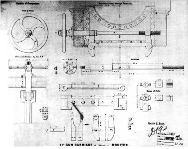
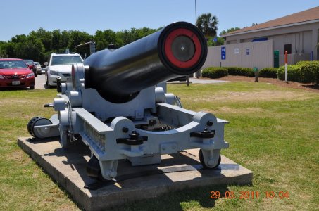
the carriage you are looking for , is like/similar to this ?I'm trying to avoid modelling garrison pieces, though I've been tempted to do the Rodmans that armed Fort McHenry in Baltimore. That's pure nostalgia from when I played at the fort as a kid. I've managed to resist that urge, so far.
I am still working on a display of one-each of all the guns Constellation carried from 1854 to present. That project is stuck on the iron carriage for the 11 inch Dahlgren she mounted on the gundeck for a few years.
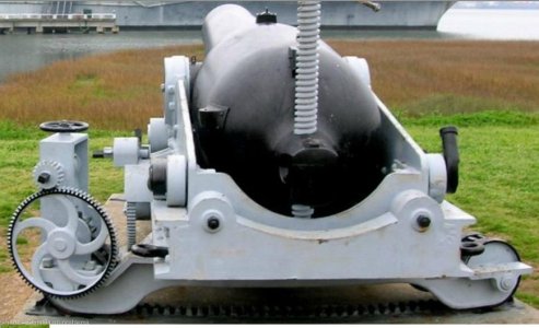
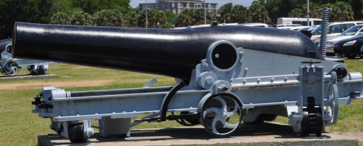
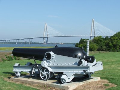
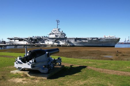
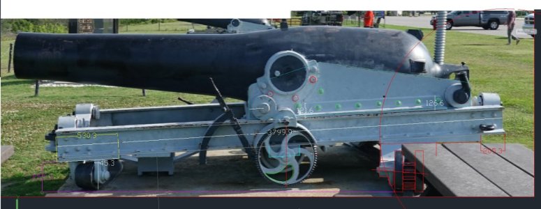
Artilleryman, regarding the photos above, where is it located, and what is its provenance? Any info would be appreciated.the carriage you are looking for , is like/similar to this ?
View attachment 505563
View attachment 505564
View attachment 505565
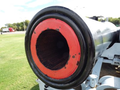
Civil War Cannons At Patriots Point
[/caption]As visitors pull into the parking lot at Patriots Point, they may notice four large cannons on the shore pointed at the USS Yorktown. Some astute...
Last edited:
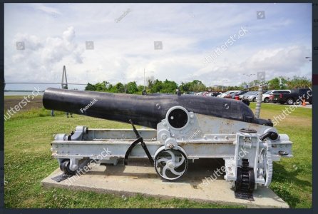
Patriot Point Dahlgren questions :
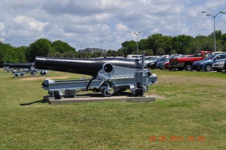
these Dahlgren do not have the bulge at the mouth , do you think the mouth has been turned or the barrel has been shortened ; I can't tell from the photographs
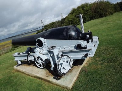
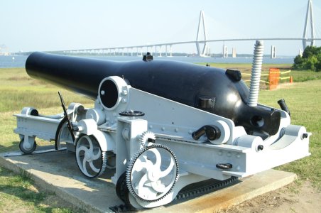
I am trying to find what is between the slides . two racks underneath the carriage to bring it forward again ? a hydraulic cylinder for recoil ?
what could be the piece under the slides ( that seems to be touching the ground ) ; it can't be for the pivot pin because the the third and fourth gun shows at the front the bracket that is missing in the other two
Last edited:
Artilleryman, could we see your other pictures of this gun? It might help answer your question. And I am going to make a 1:10 scale model of the Dahlgren XI, and seriously considering this carriage and slide for the model. (The Monitor carriage and slide is my other option.) Input from any other readers with photos or diagrams of this gun would also be appreciated. I would visit it and measure it personally, if it was not so far away from Oz. Maybe I will just do that.Patriot Point Dahlgren questions :
these Dahlgren do not have the bulge at the mouth , do you think the mouth has been turned or the barrel has been shortened ; I can't tell from the photographs
I am trying to find what is between the slides . two racks underneath the carriage to bring it forward again ? a hydraulic cylinder for recoil ?
what could be the piece under the slides ( that seems to be touching the ground ) ; it can't be for the pivot pin because the the third and fourth gun shows at the front the bracket that is missing in the other two
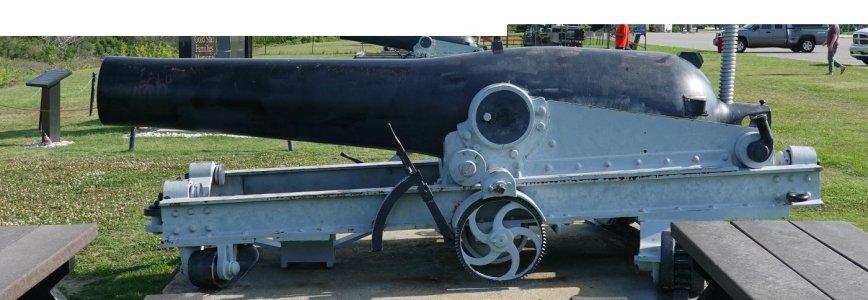
these are the best side viewsArtilleryman, could we see your other pictures of this gun? It might help answer your question. And I am going to make a 1:10 scale model of the Dahlgren XI, and seriously considering this carriage and slide for the model. (The Monitor carriage and slide is my other option.) Input from any other readers with photos or diagrams of this gun would also be appreciated. I would visit it and measure it personally, if it was not so far away from Oz. Maybe I will just do that.
Last edited:
Attachments
Thankyou for those photos and the article Carlo!contrary to what I had thought , the mystery object under the slides does indeed appear to be a pivot pin
View attachment 506342
View attachment 506343
View attachment 506344
View attachment 506345
View attachment 506346
View attachment 506347
View attachment 506348
View attachment 506349
View attachment 506350
View attachment 506351
View attachment 506352
If that is a pivot, the angle of the front wheels, and shape of the front wheel track is wrong.
And it is interesting that the original 11" smooth bore was converted to an 8" rifle using the Palliser method.(after boring it out to 13.5") That might also explain how and when the original muzzle flare was machined away.
Now, do I model the original 11" smoothbore on the monitor carriage, or the Patriot modified version on the more complex, more interesting carriage??
Last edited:
if you look, the front wheels are conical, and it is possible that the cannons can be pivoted in more ways ( in our case with the front bracket present on the 3rd and 4th cannon ) ; and that the wheels could be pivoted accordinglyThankyou for those photos and the article Carlo!
If that is a pivot, the angle of the front wheels, and shape of the front wheel track is wrong.
And it is interesting that the original 11" smooth bore was converted to an 8" rifle using the Palliser method.(after boring it out to 13") That might also explain how and when the original muzzle flare was machined away.
Now, do I model the original 11" smoothbore on the monitor carriage, or the Patriot modified version on the more complex, more interesting carriage??
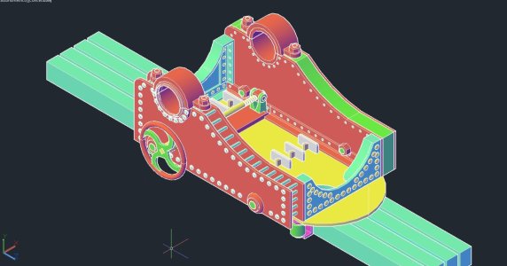
the Patriot Point shaft drawn only with the photos we have , it means inventing the system between the slides and under the carriage to bring the cannon forward again
we don't even have a photo of the 'inside of the carriage under the breech showing the plate and/or how the cheeks are connected
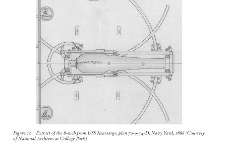
Even with conical wheels I fail to see how the gun could traverse on the pivot pin and the front track as displayed in the photo, unless perhaps the pivot point is able to be disconnected. And I note in the Kearsarge track plan #194 the tracks are centered around the pivot point. Of course, the pivot point is the front bar, shown in photo 506345, not the protrusion under the slide. The protrusion under the slide is either able to be disconnected, or is not a pivot.if you look, the front wheels are conical, and it is possible that the cannons can be pivoted in more ways ( in our case with the front bracket present on the 3rd and 4th cannon ) ; and that the wheels could be pivoted accordingly
the Patriot Point shaft drawn only with the photos we have , it means inventing the system between the slides and under the carriage to bring the cannon forward again
we don't even have a photo of the 'inside of the carriage under the breech showing the plate and/or how the cheeks are connected
View attachment 506704
We really need more information. More photos. I have sent a request to the museum.
Last edited:
Those drawings look very good! Are you measuring off the photos?excellent idea , to write to the museum - please ask ( if possible ) the slides inclination degree
if the middle one , is a pivot pin , surely it is retractable
meanwhile , I have been playing with it
View attachment 507903
View attachment 507904
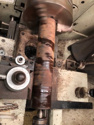
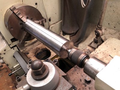
I have commenced making a 1:10 scale model of the Dahlgren 11" cannon (SML smooth bore muzzle loader). It might end up as an 8" rifled cannon, like those at Patriot Point Maritime Museum pictured above, which were converted using the Pallisser method. If there is interest I will post progressive photos.
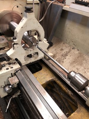
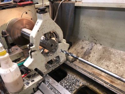
These photos are initial steps roughing the steel cylinder 81mm diameter 400mm long, and drilling an initial bore hole 16mm diameter.
1. steel bar 1800x82mm 86kg
2. roughing out a cylinder on lathe
3. 17kg cylinder 81x400mm
4. center drilling using fixed steady on lathe
5. initial drilling the bore with 16mm drill extended to 450mm (home workshop extension).
6. the drill swarf was cleared every 5mm.


Please look at thread #189 , 6th photo named “barra anteriore 2”
only the cannon in the foreground , has a cylindrical object sticking out , under what I believe to be a pivot point
other photos show how the pivot point is solidly connected to the slides and also to the front plate
in my opinion the bar to the rear , is connected to this crossbar

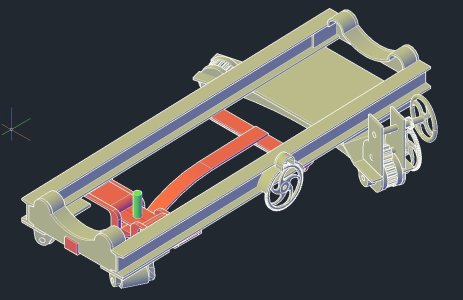
only the cannon in the foreground , has a cylindrical object sticking out , under what I believe to be a pivot point
other photos show how the pivot point is solidly connected to the slides and also to the front plate
in my opinion the bar to the rear , is connected to this crossbar


