Making Cannon

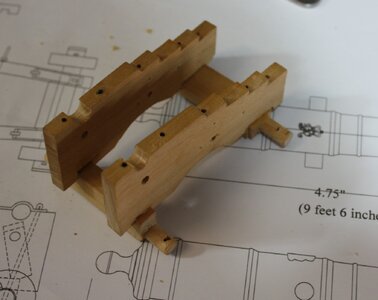
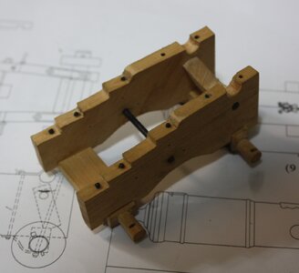
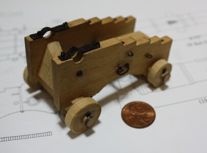
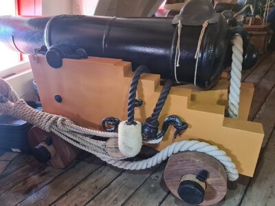
Some photos of an Armstrong Frederick carriage follow. Things such as the stays will likely never be seen by casual observers so the amount of detail that goes into it is, as always, up to the individual model builder. For a larger scale desk top model I tend to add all the details, but if I am making 30 smaller scale carriages that will be on a lower gun deck and not visible that, for me, is another story.
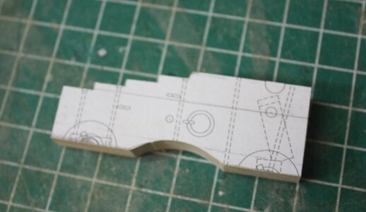
Bracket pair temporarily glued together for drilling.JPG
In the photo below the brackets are temporarily assembled and have an extra piece of sacrificial wood on top in preparation for drilling the place where the cannon trunnion will sit.
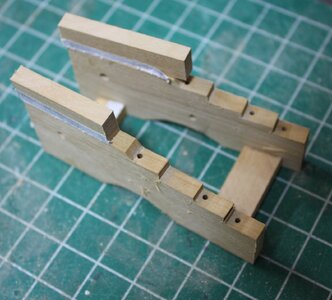
Bracket temoporarily set up for drilling tunnion resting place.JPG
Carriage brackets in place.JPG
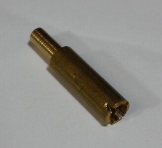
The below is an axle cutter made from scrap brass. I have made them in various sizes for rounding the ends of the truck axles.Axle cutter 1.JPGBed bolt and hind axle bolts in place.JPG
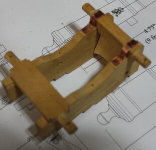
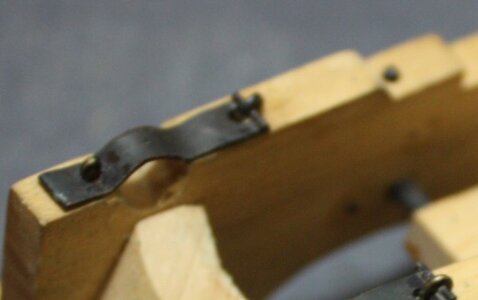
The picture below show the stays in place. on the front axle. As I used copper, once secured they are blackened with a diluted liver of sulfur and a small paint brush then rinsed. LoS will not stain the wood. Transom and copper stays temporarily  in place.JPGThe cap square is also made of copper and blackened with liver of sulfur. In this scale (1:24) the cap squares are working pieces.Cap square.JPG
If using hand tools, the stool bed requires some chisel work for the groove but can be done with a back saw and hobby knife.
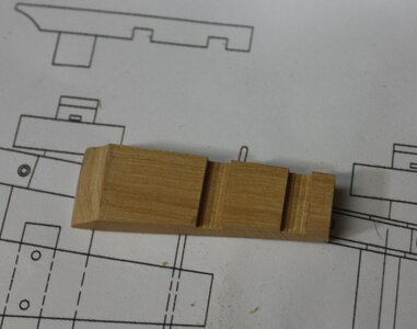
Stool bed finished.JPG
Linchpins are also made from copper then blackened with liver of sulfur after they are set in place.Copper lynch pin before blackening 1.JPG Carriage assembly finished 1.JPG
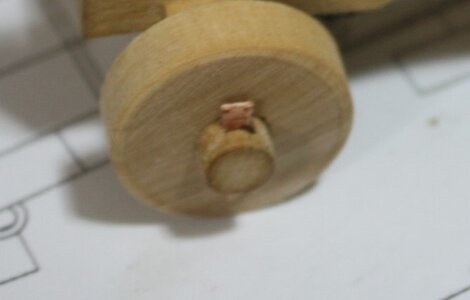
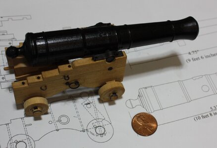
Finished cannon and carriage
Finished 1.JPG
 
Rigging long guns seems to be a mix of fantasy and reality on modern models. Blocks and lines tend to be oversized and sometimes incorrectly rigged. From James Lees The Masting and Rigging of English Ships of War, page 188 and 189 - Gun tackles Lower deck guns on first to fourth rates usually 2.5 inches (circumference) other decks and fifth and sixth rates 2 inches. Breech ropes 0.95 of the bore of the gun. The length of common blocks was about 4 times the size of the rope.

There seems to be some question and inconsistency regarding what blocks were used. Adrian Caruana was considered a leading, perhaps THE leading authority on English sea ordnance. Barring other information based on contemporary sources, information from his books should be reliable. He uses Falconer's Universal Dictionary of the Marine as well as Congreve's Treatise on the Mounting if Sea Service Ordnance for a good amount of his information so I presume it is reliable. He states on page 386 in Volume 2 that the running out tackle consisted of a rope (the fall) and two blocks (both single except for 32 pounders which had one single and one double, each equipped with a hook. The train tackle was similarly rigged.

I would not be surprised if there were exceptions, but I have not yet been able to find contemporary evidence of other rigging items and methods that are at variance with the above information.

Allan
 
Breech Ropes. This seems to be a simple enough thing but there were variations with time.

Length and circumference. As mentioned above the Lees book gives the circumference as 0.95 X bore. but there are charts with specific dimensions from Naval Guns and Stores Regulations of 1742, Ordnance Stores carried by Invincible 1747, and others. They are all similar but sizes tended to get larger over time. The below is from 1723 and 1747. I realize most of the world has gone metric, (and I envy you) but the old English information provided is Imperial. The bore diameter given below is mainly based on Albert Borgard's findings in 1712. At our most common scales, minor variations in sizes are probably not going to be noticed.

Cannon ------------ Bore----------- Breech Rope Circumference (inches) ------- Breech rope diameter (inches) --------- Length (feet)
------------------------------------------- 1723 ---- 1747---------------------------------- 1723 -------- 1747-------------------------------------

  • 32-pounders (6.4 in (160 mm)), ------ 6 --------7.5 ---------------- ----------------- 1.91 -------- 2.39 --------------------------- 30
  • 24-pounders (5.5 in (140 mm)), ------ 6 ------- 6.5 ----------------------------------- 1.91 -------- 2.1 -------------------------- - 30
  • 18-pounders (5 in (130 mm)), --------- 5 -------- 5.5 ----------------------------------- 1.60--------- 1.77 ------------------------- - 28
  • 12-pounders (4.7 in (120 mm)), ------- 5 -------- 5.5 ---------------------------------- 1.60 ------- -1.77-----------------------------28
  • 9-pounders (4.1 in (100 mm)),-------- 4 --------- 4.5 ---------------------------------- 1.27 -------- 1.43--------------------------- 28
  • 6-pounders (3.5 in (89 mm)), ----------4 --------- 4.5 ---------------------------------- 1.27 --------- 1.43 --------------------------- 27
  • 4-pounders (3.0 in (76mm)) ----------- 4---------- 4 ------------------------------------1.27 -------- 1.27--------------------------- 27
How the breech rope was rigged also varied. Many folks have used HMS Victory as a source on how things were done, but when it comes to cannon I recommend verifying with contemporary sources. One example is below. The breech rope ring in the carriage is present but they failed to run the breech rope through the ring.
Victory Cannon rigging.jpg

The breech rope was rigged in various ways over time, both at the bulwarks and at the cascabel/button of the cannon. From Caruana's The History of English Sea Ordnance, Volume II, page 383 ----- Prior to the advent of the loop on the cascabel button as seen on Blomefiled pattern guns the breech was wrapped around the button and secured with a seizing or secured to it with a cont splice. Another system that was used is described in Falconer's Marine Dictionary (T. Cadell, London, 1769) It used a wrought iron double thimble attached to the neck of the button. There were three sizes, one for 32 pounders and 24 pounders, one for 18 and 12 pounders, and one for 9 and 6 pounders. They were attached to the button with thimble straps. I have no been able to find drawings of this thimble arrangement.

The ends of the breeching were secured to a ring bolt. Initially the ends were secured to the ring with a round turn and two half hitches. By about 1750 this was simplified to a single half hitch. In both cases the tail was seized to the standing part. By 1790 a thimble had been inserted in the iron ring and the breeching seized at the throat of this and then knotted. Again, if anyone has drawings of these, that would be great.
Allan

PS I had the chart all aligned but when entering the post, it changed everything. I tried to fix it but if there is any confusion, there were the following columns
Cannon Bore Circumference in 1723 and 1747 Diameter in 1723 and 1747 and length
 
Last edited:
Hello Allan, given your background in gun research and being American, do you have any information on the armament of the frigate President? I have an unfinished model, I want to complete it in the future. Thank you.
 
do you have any information on the armament of the frigate President?
Hi Anatoly. Here you are in the UK asking about US frigate armament and me in the US with research mainly on English guns :)
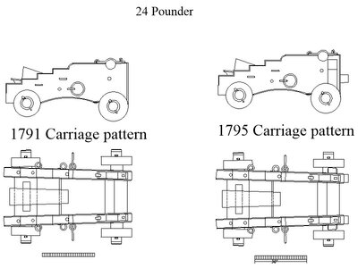
I am sorry but I had absolutely no information on guns or foundries in the US. You got my interest up so I just spent an hour doing some digging and came up with a little although I would question some authority on the authenticity of the information. Specifically the drawings of 24 pounders that I found are identified as American type and English type. The carriages are different, but the cannon are all Armstrong Fredericks.
On the plus side I have saved these drawings as they are fully dimensioned and I will go with the assumption that they are correct. Maybe contact the folks there and ask why they have English AF pattern drawings. Perhaps, that is what was used on the US frigates.
Allan

https://ussconstitutionmuseum.org/discover-learn/modeler-resources/ then scroll down to Armament and Edged weapons
 
Hello Allan, given your background in gun research and being American, do you have any information on the armament of the frigate President? I have an unfinished model, I want to complete it in the future. Thank you.
Are you building the HMS President kit from manufacturer SERGAL?
If yes, we should name her better "the so called HMS President"
There was no frigate with this name build in this time - Sergal / Mantua mentioned this with early to bid 18th century.


They say that this model represent a typical small frigate of this time -> so you can search for typical armament of typical light frigates of this time.....

or do you mean the 44 gunner USS President from 1800?
 
Last edited:
Excellent point Uwe.
I did a little digging after Anatoly's post and wondered if the British kept her armament as launched, re-armed her with Armstrong Fredericks or the newer Blomefield. So far I have found that there is scant information on US frigate armaments compared to what can be found on other navies. RMG has drawings of three different ships named President, one being a French capture. The only thing I could find there on the US frigate is a half hull model. https://www.rmg.co.uk/collections/objects/rmgc-object-66564 and a cross section drawing https://www.rmg.co.uk/collections/objects/rmgc-object-81696
Sorry to say the Sergal kit appears to be someone's fantasy as it looks nothing like the French ship captured in 1806, the US ship President 1800 (captured in1815). or the British President 1829
Allan
 
Breech Ropes. This seems to be a simple enough thing but there were variations with time.

Length and circumference. As mentioned above the Lees book gives the circumference as 0.95 X bore. but there are charts with specific dimensions from Naval Guns and Stores Regulations of 1742, Ordnance Stores carried by Invincible 1747, and others. They are all similar but sizes tended to get larger over time. The below is from 1723 and 1747. I realize most of the world has gone metric, (and I envy you) but the old English information provided is Imperial. The bore diameter given below is mainly based on Albert Borgard's findings in 1712. At our most common scales, minor variations in sizes are probably not going to be noticed.

Cannon ------------ Bore----------- Breech Rope Circumference (inches) ------- Breech rope diameter (inches) --------- Length (feet)
------------------------------------------- 1723 ---- 1747---------------------------------- 1723 -------- 1747-------------------------------------

  • 32-pounders (6.4 in (160 mm)), ------ 6 --------7.5 ---------------- ----------------- 1.91 -------- 2.39 --------------------------- 30
  • 24-pounders (5.5 in (140 mm)), ------ 6 ------- 6.5 ----------------------------------- 1.91 -------- 2.1 -------------------------- - 30
  • 18-pounders (5 in (130 mm)), --------- 5 -------- 5.5 ----------------------------------- 1.60--------- 1.77 ------------------------- - 28
  • 12-pounders (4.7 in (120 mm)), ------- 5 -------- 5.5 ---------------------------------- 1.60 ------- -1.77-----------------------------28
  • 9-pounders (4.1 in (100 mm)),-------- 4 --------- 4.5 ---------------------------------- 1.27 -------- 1.43--------------------------- 28
  • 6-pounders (3.5 in (89 mm)), ----------4 --------- 4.5 ---------------------------------- 1.27 --------- 1.43 --------------------------- 27
  • 4-pounders (3.0 in (76mm)) ----------- 4---------- 4 ------------------------------------1.27 -------- 1.27--------------------------- 27
How the breech rope was rigged also varied. Many folks have used HMS Victory as a source on how things were done, but when it comes to cannon I recommend verifying with contemporary sources. One example is below. The breech rope ring in the carriage is present but they failed to run the breech rope through the ring.
View attachment 452570

The breech rope was rigged in various ways over time, both at the bulwarks and at the cascabel/button of the cannon. From Caruana's The History of English Sea Ordnance, Volume II, page 383 ----- Prior to the advent of the loop on the cascabel button as seen on Blomefiled pattern guns the breech was wrapped around the button and secured with a seizing or secured to it with a cont splice. Another system that was used is described in Falconer's Marine Dictionary (T. Cadell, London, 1769) It used a wrought iron double thimble attached to the neck of the button. There were three sizes, one for 32 pounders and 24 pounders, one for 18 and 12 pounders, and one for 9 and 6 pounders. They were attached to the button with thimble straps. I have no been able to find drawings of this thimble arrangement.

The ends of the breeching were secured to a ring bolt. Initially the ends were secured to the ring with a round turn and two half hitches. By about 1750 this was simplified to a single half hitch. In both cases the tail was seized to the standing part. By 1790 a thimble had been inserted in the iron ring and the breeching seized at the throat of this and then knotted. Again, if anyone has drawings of these, that would be great.
Allan

PS I had the chart all aligned but when entering the post, it changed everything. I tried to fix it but if there is any confusion, there were the following columns
Cannon Bore Circumference in 1723 and 1747 Diameter in 1723 and 1747 and length
This thread is so precious! I've been searching for something similar for over 3 decades. Thank you Allan!!
 
This thread is so precious! I've been searching for something similar for over 3 decades. Thank you Allan!!
You are very welcome. I must admit I very much enjoyed getting this information together. I truly hope that it will help both scratch and kit builders. As mentioned earlier I found additional information while searching for information on American frigates. Invariably every drawing shows an Armstrong Frederick which gives me pause, but the drawings are dimensioned. While I have doubts about the accuracy of the cannon for American ships of about 1800 the carriages I found are marked British and American and show small differences.
One example follows.
Allan
 

Attachments

  • British and US GunCarriages 24 pounder.pdf
    375.5 KB · Views: 20
Last edited:
or do you mean the 44 gunner USS President from 1800?
I started the model as an 1832 "Pallad" whose "father" was "President". After the events that happened in 2014 and 2022, he decided to remake it into "President". The hull drawings match both the American and English versions of the frigate, so there were no problems here, but there are discrepancies with the armament, that's why I asked. Thank you.

NDI_8856.JPG
 
Hi Anatoly. Here you are in the UK asking about US frigate armament and me in the US with research mainly on English guns :)
I am sorry but I had absolutely no information on guns or foundries in the US. You got my interest up so I just spent an hour doing some digging and came up with a little although I would question some authority on the authenticity of the information. Specifically the drawings of 24 pounders that I found are identified as American type and English type. The carriages are different, but the cannon are all Armstrong Fredericks.
On the plus side I have saved these drawings as they are fully dimensioned and I will go with the assumption that they are correct. Maybe contact the folks there and ask why they have English AF pattern drawings. Perhaps, that is what was used on the US frigates.
Allan

https://ussconstitutionmuseum.org/discover-learn/modeler-resources/ then scroll down to Armament and Edged weapons
Thank you very much!
 
Before going into carriages the following is a group of drawings of various patterns with dates they were mostly in use that may help in selecting barrels for a build. While the British group is pretty much complete, to date these are the only reliable Spanish patterns I have found. I would love to see additional Spanish, French, Dutch and others from about 1500-1800 if anyone has them.
View attachment 451760

Carriage designs varied with era and country. My main interest has been English ships from the 17th to the early 19th century so most of the research findings deal with that area. Prior to the era when four trucks (wheels) were incorporated some carriages had two trucks at the front of the carriage and skids that were part of the bed or brackets instead of rolling trucks at the rear.
View attachment 451673

Bed and Truck Carriages
There is very little in the way of drawings that I could find for carriages prior to 1721. If anyone has drawings prior to 1721, based on contemporary sources, please jump in.

Early versions of carriages with four trucks had beds that extended beyond the edge of the brackets on all sides. From Lavery's The Arming and Fitting of English Ships of War, page 127: "They differed from later design in several respects. The bed was very large, extending beyond the brackets in all directions. The axles were mounted above the bed, whereas in later versions they were usually mounted below it. They were quite complex in construction, and seem to have been individually tailored. "

The following is based on Richard Endsor's a picture of a carriage from the HMS London 1656 in The Master Shipwright's Secrets, page.266
View attachment 451769
I could not find any contemporary drawings of the earliest carriages other than the one below from 1691 which is quite simple in its rendition.

View attachment 451679


Thomas James' Book of Artillery has several carriages from 1721 and 1725. There is some confusion in his descriptions according to Adrian Caruana, but the drawings he shows are very similar and probably better than anything else most of us have seen for this time period. There was some redesign about 1725 but for our purposes and scales the most noticeable thing during this time period is that there is an extended bed whereas beds were eliminated on many new carriages starting around or just after 1730. I could not find anything on how early the extended beds were used, but as the bed is quite visible this is something to consider if the model is for a ship built prior to 1730.

A general note: Considering the era as early as the 16th century and then through the early 19th century, based on what contemporary information I could find to date, the brackets were never parallel to each other.

View attachment 451680
Dear AllanKP69
it's possible have the file to me too :)
thanks Shota
 
Thanks for this and your log on the ships boats.
Thanks Grant and Roger :)
It sounds like you have enjoyed it as much as I have in preparing them and it is immensely gratifying to know folks such as yourself liked them. I fully understand that most builders do not care to change what is in a kit as there is extra cost involved, but boats and guns can be done well and cheaply, just takes a bit of time. I have always felt that if a ship modeler is more worried about saving time than the end result, they might want to consider a change to some other hobby.

Grant, Off topic for a second. I may have mentioned this earlier on but when I see your posts and Cape Town it brings back fond memories of my one and only trip to SA and Mozambique. I am currently re-reading The Covenant by Michener as it has been about 40 years since I first read it. Assuming it is accurate for the most part, as was his wont when writing his tomes, SA has a fascinating history.

Allan
 
Last edited:
I have some Blomfield, Armstrong and Constitution barrels which I could offer.
Just a little bit of information that some may find interesting, especially if building a model of the USS Constitution. The Constitution today sports Armstrong Frederick cannon barrels for the long guns. I thought it odd that the US could get these from England when she was being built so I wrote to Dr. Carl Herzog, Public Historian for the USS Constitution asking about this. He responded as follows:

Hi Allan,
When the ship began its major restoration in the 1920s, a new set of guns were fabricated for display. These were patterned off the British guns based on a mistaken belief at the time that that is what had been put on board when the ship was launched. It was not.

These historically inaccurate replicas remain on the ship today due primarily to the cost required to replace them. Note that none of these are working guns. Although cast to about the same weight, they were not designed, manufactured or proofed to take live shot.

Hope that's helpful,

Carl Herzog, PhD
 
Back
Top