Master Frame Abbreviations

Joined
Oct 15, 2017
Messages
986
Points
403

Hell all you great ship builders!

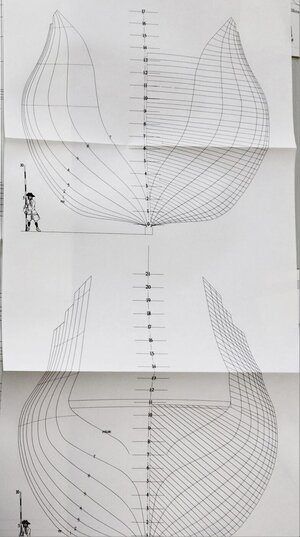
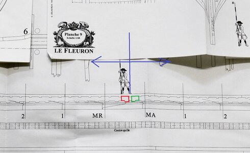
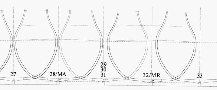
Quick question for anyone willing to help educate me. I'm looking at the framing plans for Le Fleuron from Ancre. There are two key frames noted by "MA" and "MR". I thought these were referencing "Master" frames, one moving aft and one fore. Can anyone tell me what these abbreviations stand for? I'm attempting to continue to educate myself. Interestingly enough, in the plans there is one frame illustrated, but labeled 29, 30 and 31. I'm assuming these are 3 frames of the same dimensions.

I really do enjoy the learning process of this hobby.

Thanks.
Ken
 
I do not have the planset in front of me, so I had to work with the available photos of my planset review

in moment I forgot the correct definition of MA and MR, because it is coming from the french, drawings are not translated into english.
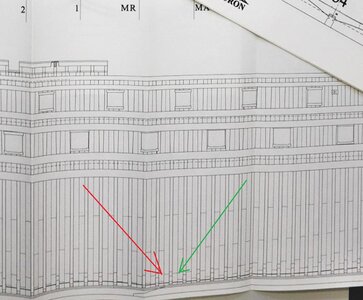
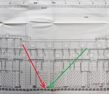
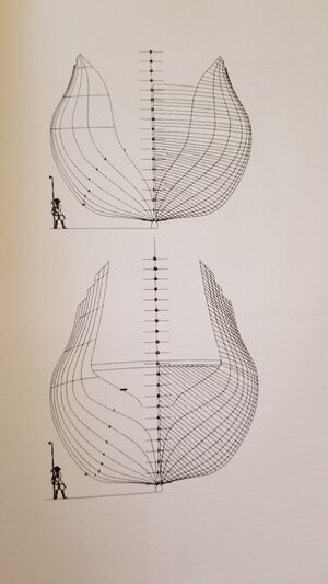
It is the change of the direction of the view, means towards the bow and towards the stern

IMG_20181.jpg

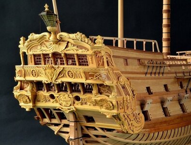
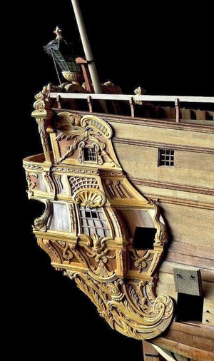
In between MA and MR also the orientation of the frames, the location of the floor timber is revised and changing

IMG_20211a.jpg

IMG_20191.jpg IMG_20211.jpg

Frames are 29,30 and 31 are identical and located between MA and MR - I guess 31 will be only 180° turned sitting on the keel

Unbenannt.JPG
 
My apologies Uwek. I should have illustrated with the plans myself to help with the explanation. You have confirmed my understanding, which gives me the confidence to move forward. As always, you've taken the time to help another, less experienced builder and it's very much appreciated.

I am considering the Le Fleuron as my first scratch build. If I do, I will not build individual framing timbers. It will be hybrid build, as a PoB, and "shell" construction, following the approach Andrey Kudin used in his Le Fleuron. If I do, I will muster up the courage to start a build log, but the start of the build project is still quite a ways off, maybe a year. I am a fanatical planner I'm sure people have heard the saying, "measure twice, cut once"? I'm more like measure 16 times and cut once.

Again, thanks Uwek. I hope some day to pay it back and help others.

Cheers,
Ken
 
Last edited:
My apologies Uwek. I should have illustrated with the plans myself to help with the explanation. You have confirmed my understanding, which gives me the confidence to move forward. As always, you've taken the time to help another, less experienced builder and it's very much appreciated.

I am considering the Le Fleuron as my first scratch build. If I do, I will not build individual framing timbers. It will be hybrid build, as a PoB, and "shell" construction, following the approach Andrey Kudin used in his Le Fleuron. If I do, I will muster up the courage to start a build log, but the start of the build project is still quite a ways off, maybe a year. I am a fanatical planner I'm sure people have heard the saying, "measure twice, cut once"? I'm more like measure 16 times and cut once.

Again, thanks Uwek. I hope some day to pay it back and help others.

Cheers,
Ken
Hallo Ken,
That's what friends are for

Good to hear, that you prepare the Le Fleuron project.

Also the preparation and planning of such a project is part of the "building", so you could start already a building log and share with us the planning ..... just an idea
 
Uwek,
As always, you make a great point. I will follow your suggestion, if I move forward. With any project I've worked on or managed, there is a pre-planning phase, the feasibility study. This is the phase that determines whether a project will take place, based on many factors, cost, benefit, timeframe, etc. For me the feasibility phase will determine if I actually start this build, which includes the planning phase, or take on something slightly less complicated. My decision predominantly depends on whether I feel I have the skill set, dedication and patience to be successful.

Even during this phase, I am documenting my steps so that I am able to share them, if I decide to move forward.

I am encouraged by the work of many other SoS members, along with the endless support of those pioneers that have forged the path before me.

I will let you know as I go.

Thanks,
Ken
Hallo Ken,
the big advantage with the Le Fleuron is the fact, that the monograph was well designed and there are some great models already built by modelers. So most problems or difficult parts were already solved by somebody, so therefore you can find them documented and shown, also here in our forum.
In addition our member @Gilles Korent , who made also the english translation of the monograph, knows the plans and model very well. But also modelers like @KUDIN Andrey or @Joachim working intensively on their models......
I am crossing all fingers, that your feasibility study will end in a positive "GO"
 
As the original plan sheets drafted by the author are included in the subsequent translated versions of monographs, the written references contained in the plan sheets themselves are not translated.
MA = Maître couple (Master frame) Avant (forward). It may also be label "Mav" in some monographs.
MR (may be labeled "Mar" in other monographs) is the reference for Maître couple arrière = master frame aft or "rear master frame".

Sounds confusing doesn't it!
G.
 
Thanks Uwe @KUDIN Andrey's log extensively on Youtube. It is inspiring and a great reference for others. I will also look for @Joachim's log.
Thanks.
Ken


Hello Ken,

ich habe hunderte von Fotos über den Bau der Fleuron von verschiedenen Modellbauern.
Bei Interesse würde ich sie Dir gerne schicken, die Menge der Fotos ist aber für für dieses Forum zu groß.
Deine Private Mailadresse wäre hierfür besser geeignet.
Entschuldigung , das ich auf Deutsch schreibe , mein Translator will zur Zeit nicht.

I have hundreds of photos of building the Fleuron from various model makers. If you are interested, I would be happy to send them to you, but the number of photos is too large for this forum. Your private email address would be better suited for this.

Grüße
Karl

.jpg
 
As the original plan sheets drafted by the author are included in the subsequent translated versions of monographs, the written references contained in the plan sheets themselves are not translated.
MA = Maître couple (Master frame) Avant (forward). It may also be label "Mav" in some monographs.
MR (may be labeled "Mar" in other monographs) is the reference for Maître couple arrière = master frame aft or "rear master frame".

Sounds confusing doesn't it!
G.
Giles,

Thanks, everything you've mentioned confirms my general understanding and offers more clarity. I find comfort when information further supports what we think we understand. Thanks for helping me build my own knowledge.

Cheers,
Ken
 
Hello Ken,

ich habe hunderte von Fotos über den Bau der Fleuron von verschiedenen Modellbauern.
Bei Interesse würde ich sie Dir gerne schicken, die Menge der Fotos ist aber für für dieses Forum zu groß.
Deine Private Mailadresse wäre hierfür besser geeignet.
Entschuldigung , das ich auf Deutsch schreibe , mein Translator will zur Zeit nicht.

I have hundreds of photos of building the Fleuron from various model makers. If you are interested, I would be happy to send them to you, but the number of photos is too large for this forum. Your private email address would be better suited for this.

Grüße
Karl

View attachment 294640
Thank you Karl!

I would welcome all input on Le Fleuron. The more information I can gather the better. My personal email is; kjd6262@yahoo.com.

Looking at the image of the model in your post gives me chills. What wonderful craftsmanship.

Please feel free to send any and all information you have.

Danke,
Ken
 
Hello Ken,
with this amount of data, my email programm is on strike.
I made a link fom my photo album in the SOS Forum,
from which you can download all the photos of the FLEURON.
regards
Karl


Dieser Link ist nur ein Monat gültig!!!

Google Tranlator

e03_0610.jpg
 
Last edited:
Hello Ken,
with this amount of data, my email programm is on strike.
I made a link fom my photo album in the SOS Forum,
from which you can download all the photos of the FLEURON.
regards
Karl


Dieser Link ist nur ein Monat gültig!!!

Google Tranlator
Ich kann nur sagen, Karl: WOW!!. Es wird mir nicht an Informationen/Abbildungen dieses wunderschönen Schiffes mangeln!!! Ganz zu schweigen davon, dass ich damit beschäftigt sein werde, alle diese Dateien herunterzuladen. Nochmals vielen Dank für Ihre Freundlichkeit, die Sie mir entgegenbringen.
Danke,
Ken


All I can say Karl is WOW!!. I will not be short on information/illustrations of this beautiful ship!! Not to mention I will be busy downloading all of these files. Once again, thank you very much for your kindness in sharing.
Thank you.
Ken
 
Hello All,
My task continues, to determine whether or not I start my Le Fleuron project or whether to start something a little less challenging. I already know I will not build a full PoF version. So that leaves me with a PoB using the 16 key master frames (in my case bulkheads) Jean Boudriot used from the original drawings to build the volume of the ship's hull.

I found that I actually need to build some of these ship components to determine that I have a comfortable enough understanding to make the decision to move forward.

This is where I need the communities help with a few questions. I will share some of my assumptions. If they can be confirmed, I will change them from assumptions to rules, by which I move forward. Included are some of Gérard Delacroix's drawings and excerpts from the monograph, which I hope will clarify my questions.

The first image images are the Vertical Sections, showing the master frames (bulkheads) I would use to build the hull, MA & 1-7 forward, and MR & 1-7 aft., for a total of 16 master frames. This is all very clear to me.

20220308_122559.jpg

From the monograph, Mr. Delacroix states, "The definition of the hull is again represented to the outside edge of the framing without taking into account the different thicknesses of the planking." This is understood as well. I would be building an "exoskeleton" of the hull, by building 4 layers of planking, 3 layers of 2mm (6mm) limewood +PVA, and one 2mm layer of finished planking (wood still to be determined). So I will need to reduce the outer most edge of the bulkheads by approximately 4mm, 2+2+2=6-2 for sanding. Final adjustments would be made with filler if needed.

Here is where it gets a little confusing for me as my understanding of the plan drawings is conceptual only.
I will use the forward most master frame as an example to ask my questions. In this case frame #7.

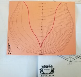
I've outlined in Red the "outer edge" of #7 master frame.
20220308_120053 (2).jpg

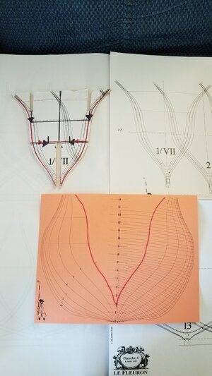
The next image is that of the same #7 master from from the Frames plate of the plan. I have included a bulkhead I've cut using the frame drawing as a template. I understand the frame drawings show the radius of the shape of the hull over the width of the frame, which is much more pronounce the closer the frames get to the bow and stern of the ship. I need a little help understanding the frame line meanings as the relate to what I am trying to do. Example below.

The Red line shown on the orange card above is the "outer edge" of frame #7 on the Vertical Sections plan. The same line on the frame drawing and on the bulkhead I cut is outlined in Red.

20220308_120053.jpg

My understanding of this is, the inner most lines in the frame drawing are directionally towards the bow (growing more narrow) and outer most are to the stern, widening as the hull does, moving aft over the width of the frame. If my understanding is correct, the "outer edge" of the frame should be represented by the outer most solid line in the frame drawing. I'm assuming the discrepancy lies in my understanding or lack of it when it comes to illustrating these complex shapes and radius. But why is there a difference between the two drawings.

Ok, I know I "took the long way to Grandma's house" ROTF Here is my question; using the frame drawing #7 as an example, what line am I cutting the bulkhead to the represent the outer most edge of the frame.

FYI, I am getting closer to make a decision and most likely will be starting the project in the fall. I have already taken many photos of what I've done so far and will include them in the build log, if/when I start.

Thanks in advance for everyone's help. I hope to pay it forward some day!

Ken
 
Last edited:
Hi Ken,
I wish you the best on this ambitious project - However, I do have a question myself. If you are converting this to a POB, then how are you going to address the deck levels and the internal furnishings. The POF has knees and such that the deck levels rest on. I assume that you are only going to build one deck and that is on the very top level. Usually, POB all the Bulkhead frames are solid - however, unless this is somewhat of a hybrid mix of where the Bulkheads are mostly cut out.
Hi Donnie,

You are correct, this will be a "hybrid". I wanted to go in this direction as I'm aware of my own limited knowledge and limited personal patience as it would relate to the work on 60+ individual frames and all of their related components. With that said PoB is the direction I will be going, if I go. I do want to build many internal components and structures of the ship and therefore will require internal decks to place them all on.

If you take a look at the upper left corner of the last image in my last post you can see the forward most bulkhead. One the template you can see, vaguely, 3 horizontal lines, the decks. The top deck is the faint dotted line, the middle is the black line and the bottom is the line with the black and red arrows pointing inboard. Once the hulls shell is completed and harden, everything above the bottom line of the bulkhead will be removed. That will be done for every one of the 16 bulkheads and form the support for the bottom deck. Those inboard arrows show where the bulkhead has already been precut to facilitate the easy removal of the top 2/3 of the bulkheads. I will glue the shell's planking to raw wood of the bulkheads below the bottom deck line, while applying a release agent to the bulkhead edges above the line, to ensure the first layer of the upper shell planking does not stick to the part of the bulkheads I intend to remove.

The "new top" of the bulkheads will form the support for the bottom deck. I will create the other supporting components off of that first deck, using plan's dimensions, deck beams, hanging knees supporting them, etc. As the decks will not be exposed from above, I will most likely not include certain deck components, ledges, carlings, etc. This will allow me to build an internal decks, internal structures, without having to build every single component. Perhaps a violation to the purists, but it will allow me to maintain focus on those structures I want to emphasize.

This methodology is not my brain child, but a method well known to a number of Russian Masters. It is called the "Scorlup" method. I first saw this and it was my inspiration from @KUDINANDREY's build log.

If a picture is worth 1,000 words, Andrey's video (one of many on his Le Fleuron build) is worth 1,000,000. To me at least. Thank you Andrey!!

You can see the video relevant to this method here;

If I decide to start this, I will be committed to its finish. This is why I'm being so deliberate in my preplanning. It would be a sizable commitment for me. And there is no doubt, I would not start this project if I didn't have the incredible support of our great SoS community. I will need a lot of help.

Cheers,
Ken
 
Last edited:
I have seen his video's, but I did not go back far enough to realize that he had done his hull like this - quite interesting I should say.
 
Hello All,

I have to call myself out and correct an error I made in my initial post.

As part of my preplanning efforts, I was doing some research. I read the Ancre Monograph on Le Fleuron, cover to cover, three times. Still I had some unanswered questions on hull construction. So I spent countless hours and many, many cups of coffee over a couple of days, right before posting, reading 74 Gun Ships, Volume I, by Jean Boudriot.

In my posts, above I referenced a passage from Le Fleuron's monograph, and drawings where I incorrectly credited Jean Boudriot, when it should have been Gérard Delacroix. I have corrected the error. My apologies. I hold both gentlemen in the highest regard. Without their acumen and work-products many of the answers to our questions might very well remain in obscurity. Saluer!

The thing that is crazy is that, 4 1/2 months after making that post, at 3AM this morning I awoke from a dead sleep, sat up in bed and consciously realized my mistake! Hahaha. I'm not sure what that says about how my brain functions. A little lag maybe. I'll not ponder too deeply on it. I'll save my brain power for the next problem solving task I run into on the Le Fleuron. I've decided to move forward with the build, although it is a ways off.

With all that said, I will close with;

Mes excuses les plus sincères Monsieur Delacroix.

Ken
 
Last edited by a moderator:
Hi Donnie,

You are correct, this will be a "hybrid". I wanted to go in this direction as I'm aware of my own limited knowledge and limited personal patience as it would relate to the work on 60+ individual frames and all of their related components. With that said PoB is the direction I will be going, if I go. I do want to build many internal components and structures of the ship and therefore will require internal decks to place them all on.

If you take a look at the upper left corner of the last image in my last post you can see the forward most bulkhead. One the template you can see, vaguely, 3 horizontal lines, the decks. The top deck is the faint dotted line, the middle is the black line and the bottom is the line with the black and red arrows pointing inboard. Once the hulls shell is completed and harden, everything above the bottom line of the bulkhead will be removed. That will be done for every one of the 16 bulkheads and form the support for the bottom deck. Those inboard arrows show where the bulkhead has already been precut to facilitate the easy removal of the top 2/3 of the bulkheads. I will glue the shell's planking to raw wood of the bulkheads below the bottom deck line, while applying a release agent to the bulkhead edges above the line, to ensure the first layer of the upper shell planking does not stick to the part of the bulkheads I intend to remove.

The "new top" of the bulkheads will form the support for the bottom deck. I will create the other supporting components off of that first deck, using plan's dimensions, deck beams, hanging knees supporting them, etc. As the decks will not be exposed from above, I will most likely not include certain deck components, ledges, carlings, etc. This will allow me to build an internal decks, internal structures, without having to build every single component. Perhaps a violation to the purists, but it will allow me to maintain focus on those structures I want to emphasize.

This methodology is not my brain child, but a method well known to a number of Russian Masters. It is called the "Scorlup" method. I first saw this and it was my inspiration from @KUDINANDREY's build log.

If a picture is worth 1,000 words, Andrey's video (one of many on his Le Fleuron build) is worth 1,000,000. To me at least. Thank you Andrey!!

You can see the video relevant to this method here;

If I decide to start this, I will be committed to its finish. This is why I'm being so deliberate in my preplanning. It would be a sizable commitment for me. And there is no doubt, I would not start this project if I didn't have the incredible support of our great SoS community. I will need a lot of help.

Cheers,
Ken
Yes indeed Andreys vid shows it great. I didn't realize he used this method too.
 
Back
Top