Wow, this is a very comprehensive build log. Well done so far.
-

Win a Free Custom Engraved Brass Coin!!!
As a way to introduce our brass coins to the community, we will raffle off a free coin during the month of August. Follow link ABOVE for instructions for entering.
-

PRE-ORDER SHIPS IN SCALE TODAY!
The beloved Ships in Scale Magazine is back and charting a new course for 2026!
Discover new skills, new techniques, and new inspirations in every issue.
NOTE THAT OUR FIRST ISSUE WILL BE JAN/FEB 2026
You are using an out of date browser. It may not display this or other websites correctly.
You should upgrade or use an alternative browser.
You should upgrade or use an alternative browser.
Mini Hobby 80502 1/350 Scale USS Enterprise CVN-65 Early
- Thread starter Mikey25252
- Start date
- Watchers 12
- Joined
- May 8, 2021
- Messages
- 53
- Points
- 78

Thanks its a labor of love for meWow, this is a very comprehensive build log. Well done so far.
- Joined
- May 8, 2021
- Messages
- 53
- Points
- 78

Part 7 Deck Edge Aircraft Elevators
It has been some 42 days since my last post and I know that I didn’t work every day so say 38 days at around 3 hours per day would mean I spent around 114 hours making the 4 elevators. Because of the number of photos that I want to attach I may have to break this into 2 posts.
On the ship each elevator is approximately 4000 square feet. They are capable of lifting two aircraft weighing up to 100,000 pounds each. The elevators are vital to operations on any aircraft carrier. The Enterprise, Forrestal, Kitty Hawk and Nimitz Classes all have 4 elevators but the Gerald R Ford Class has only 3 so any one going out of operation would seriously hamper the ships ability to function. I saw Elevator 2 jam a couple of times during the 1978 deployment. They had to rock the controls from up to down repeatedly to un-stick it. This is one reason why it was partially plated over during the major refit that followed that deployment. The plating was to keep the giant platform from flexing and locking up in the guides. They plated over the drain holes under the deck by 2012 which is an indicator that the deck was solid by that time too. I am sure that all 4 elevators were completely plated over sometime during the final 12 years of service. I believe the Enterprise was unique in having grated elevators. I never served on another carrier with them nor heard of one. I imagine it was tried for its ability to shed water quickly, weight and/or cost reduction.
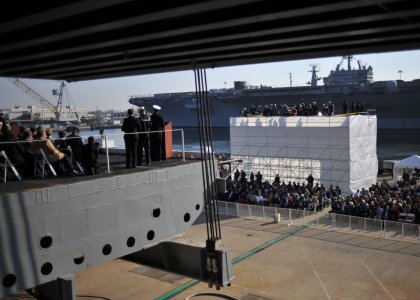
In this photo from the decommissioning in 2012 you can see that the drain holes are plated over. Compare that side view to the one below.
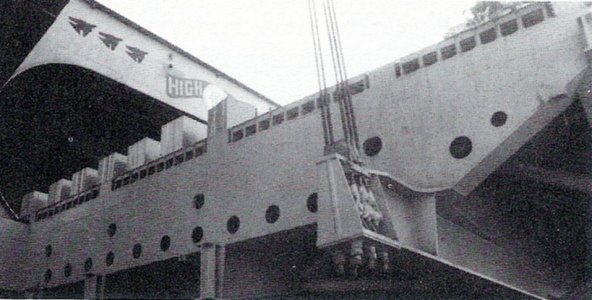
The drain holes are open in this photo of Elevator 2 in the 80’s. Coupled with the grated deck the elevators could shed water quickly. Note the cable attachment points.
The actual elevators have a 5 sided exterior frame. It slopes up at the outboard edge and on the outboard plate. There are 4 inner transverse beams. Two of these have a support truss attached on the bottom while the two center beams have a curved cut out center section. I am not sure but I think the ends of these are part of the locking device. On the side of the elevator with the angled extension there is a frame that goes from that side straight forward to the outside wall bisecting the extension. There is a cross brace to strengthen the framework and a number of struts to brace everything else. There are drain holes just under the deck and lightening holes along each side. The sides on the inboard edge have a piston that rides in the elevator guide track.
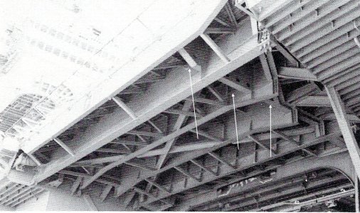
This photo of Elevator 1 from the same time as the one above shows the construction of the support system very well. The white arrows are pointing to the bisecting frame.
I have a couple of stories that involve the elevators. The first involves my wildest elevator ride. It was not unusual to ride an elevator up or down if you were moving heavy equipment and you were riding with it. If you were riding brakes in a plane going up or down you stayed in the cockpit while they ran the elevator. The ride I’m thinking about occurred on the morning of 2 October, 1976 at Latitude 000 degrees, 00 minutes and East Longitude 141 degrees 15 minutes. On this day I was inducted into the hallowed ranks of Trusty Shellbacks.
We rode up to the flight deck on Elevator 2 but in order to get there we had many hurdles to cross. We were rousted out in the dark. I worked nights so I was already up but it was dark when the festivities began. The Trusty Shellbacks who took us in charge saw to it that we were properly attired. Dungaree pants inside out and backwards. A ”T” shirt inside out and backwards with a 12 inch P stenciled on the front and back and a set of underwear also inside out and backwards, stenciled with a P, worn over the dungarees. To promote good order and discipline wherever we travelled we did so on our hands and knees probably so we could be swatted more easily with all those shillelaghs (worn out canvas fire hose jackets). We got to experience all the culinary delights of Pollywog Breakfast. After that we waited in the shop and had many fine adventures courtesy of the illustrious Shellbacks in our squadron. When our division was finally called away we crawled to the hanger and then to Elevator 2.
We were placed face down on the elevator. I have no idea how many of us but at least a couple hundred. The Shellbacks kept popping their shillelaghs but left us alone on the elevator (I wonder why). Whenever the elevators travel, they sound a klaxon horn (it makes that ah-ooga, ah-ooga sound) a warning to anybody nearby. Up we went only to be hit with several streams from salt water fire hoses as we rode up. I remember grabbing that grated deck and hanging on for dear life because it felt like I was going to be flushed overboard. There was a ring of Shellbacks screaming and waving shillelaghs at the top of the elevator opening. I actually felt a glimmer of fear.
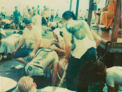
The moment I met the Royal Baby, there were so many Pollywogs we had 3 Royal Babies. I gave my camera to one of the Shellbacks and he caught this for me. In the background to the right is the Royal Court.
The rest of the morning was spent crawling around the flight deck making manners with Neptune’s Royal Court, the Royal Baby, the Royal Dentist, the Royal Barber and the Royal Devil. Then there were pleasant interludes in the chute, the stocks and finally the tank. I thought I would never be clean again. I am glad that I went through it though. It wasn’t mandatory just a bit of fun at the Pollywogs expense. They ran the elevator repeatedly to cycle all the Pollywogs through initiation. They went by division and there were 61 divisions if I counted right. I later heard that over 60% or around 3500 of the crew were Pollywogs.
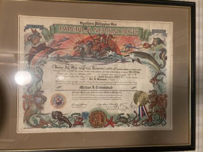
My Shellback Certificate from 1976.
We were in the infancy of the Naval Aviation Tool Control Program in 1976. Tool control is being able to account for your tools 100% of the time. It was a spin-off of the FOD ( Foreign Object Damage specifically damage to engines,)reduction program. It was drummed into us that a lost tool could potentially destroy an aircraft engine or become a missile when blown by aircraft exhausts. Heaven forbid you lose a tool in the cockpit. When I reported to the squadron in June of 1975 there really wasn’t much of a program compared to what it became later. It was just assumed that you would take care of your tools because you were told to. One of the first things that happened after checking in was to go to the tool room and get issued tools. The tool room was simply a room with a lot of tools in it. Nobody worked in the tool room that I knew of and anybody could go in and get anything they needed within limits. I’m sure someone was in charge but it wasn’t obvious. The only restriction was that you had to go to Maintenance Control and check out the key and they did not just hand it out. There had to be a valid reason. The checkout/in was logged but records of what you took were on you.
Three of us IWT technicians reported aboard at the same time and one of the Second Class Petty officers in the shop took us around the squadron. One stop was the tool storage room. We were directed to take one of the tool boxes, a box much like my father’s fishing tackle box. The lid opened in the center and as it opened 2 levels of trays opened with it. It was well used but sound. It was painted Royal Mace Green, the squadron color, and stenciled with yellow shop and squadron markings. Primary storage was a large space in the bottom of the box. The petty officer with us went through the bins and selected what tools we would need. But when we were done he entertained requests for other items like hacksaws and hand drills (the old fashioned hand cranked kind, In Naval slang a Hurdy Gurdy).
Back in the shop we used a paper form to record all of the tools in our new boxes. If you weren’t honest you could get away with some swag here. Nobody checked my inventory when I was done. This went in a document protector and was kept in the box. A copy went to the shop supervisor to be filed away. We were told to inventory the boxes contents once a quarter. We were also told that all of these tools were our responsibility and when we left the squadron they would all be inventoried and returned to the tool room. Any discrepancies would be deducted from our pay. I didn’t make much back then so the thought of losing any of my pay did not sit well with me. It made more sense to me to inventory my tools every day.
All of the tools were placed in the box as we liked but there was no organization other than the trays were convenient for small tools like pin extractors and socket wrenches everything else went in the bottom. I probably had 50 tools and consumables in my box. I also had a lock and key to keep it secure, a carpenter’s leather tool pouch with a web belt and nylon bag/cover to keep everything in the pouch, two kinds of safety wire, two kinds of electricians tape, a TL-29 Electricians knife with a belt pouch and a Navy flashlight also with a belt holder. That was in 1975. Despite the lack of organization I never lost a tool.
By 1976 things were changing. The shop received a wall tool box and 4 aluminum attaché cases. We also received layered foam sheets to organize the tools in the cases. Every shop in the squadron was doing this locally but it was a navy wide change. Each tool would have a cut out where only it could go. Ideally the cut out was colored to highlight a missing tool (shadowed). At a glance you could tell if everything was where it was supposed to be. The tools we had in the boxes were reduced to the minimum as determined by us. Any tools that didn’t make the cut for the attaché cases and couldn’t be stored in the wall box were turned in. I said goodbye to my green tackle box. These new boxes were inventoried at every shift change and after every job you went out on. Nobody had their own set of tools any more.
New tool pouches were designed by our supervisor. He did a pretty fair job with the pouches and we all collaborated on what was essential to put in them. He did the lay out and worked with the squadron PR (Parachute Rigger) who would sew the pouches up for us. Now every shop in the squadron was doing this too so the Rigger was pretty busy, he still had his regular work to keep up with too. The boss designed a pouch of heavy canvas, double stitched with nylon covered hems. It had 2 rows of slots separated by a central space and covered by a Velcro closed flap. There was a secure pocket to hold the speed wrench located on the outer panel and a built in flash light holder.
The central space could hold the inventory form and consumables for whatever job you were going out on. The inner side was conventional but (here’s that fatal but) the outer panel was held closed by more Velcro down the sides. He had it made this way so at the end of the job you could open the whole thing up and clean any bits of safety wire, hardware and other debris, leaving the pouch clean for the next job. But when opened, the outer row of tools was now pointing down if you were wearing it! This was okay in the shop but not so much if you were wearing the pouch on deck. When the pouches were new the tool slots were tight but they soon loosened up with use.
Velcro is pretty good stuff but after it is used extensively it gets weak and can disconnect pretty easily. We were quick to point out that while the ease which the pouch could be cleaned was nice, the fact that the thing could pop open on deck and drop tools everywhere might be asking for trouble. We wanted the pouch sides sewed up but the PR was buried in work and would not be able to do this job for a while. The boss did not believe it would ever pop open. We had to use those pouches for almost a month and don’t get me wrong they were miles better than the carpenter’s pouches. You could run down the flight deck and things stayed where they were supposed to. Unfortunately the flight deck is a very dirty place and constantly exposed to the weather so the pouches were soon dirty, oily and damp and this adversely affected the Velcro holding the outer panel closed. The closure for the cover flap held up pretty well but when you opened the flap the outer panel tended to drop open under the weight of the tools on it (remember that speed handle). You had to hold it closed until the flap was secured again.
One fine day I was sent up on deck to work on the RADAR on one of our planes. We were shorthanded and I had to work on the gripe by myself. I took a ladder, a pouch, my flight deck gear and headed up. I found the plane on elevator 1. Usually our aircraft were parked along the bow or in an area called the 6 pack but it was not unheard of to put one on an elevator. I got set up, carefully positioned the ladder, got the radome opened up, located a power cord and got the aircraft powered up with some help from our roving CDI (Collateral Duty Inspector, it takes two people minimum to apply 400hz aircraft power). It was fairly easy to verify the gripe and determine a faulty box and I climbed up on the ladder to remove the defective item. The thing about using a step ladder on the elevators was those grates were just the right size to swallow one of the legs. The legs had rubber blocks to keep them from moving around but shifting your weight could cause one to jerk and slip into a hole.
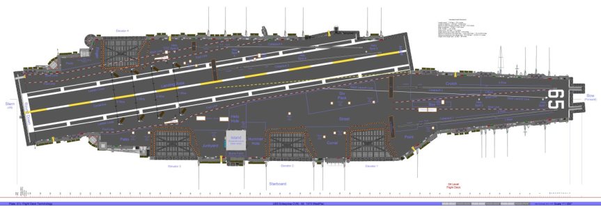 Plate 07J Flight Deck Terms
I will probably refer to various parts on the flight deck from time to time so this should help. The Six Pack is just across from the angle forward of the island to the starboard of the foul line. It was called that since you could park six smaller aircraft there say A-4’s or in my case A-7E’s.
I was removing the power supply on the forward RADAR package which required swinging it out to starboard from the nose to access all the plugs and hardware. Disconnecting the cables went well but when I went to the pouch to get a ratchet and socket for the bolts I had one hand on the flap and one hand for the ladder. Out of hands, I was using my body to hold the RADAR package open. The weight shift caused the ladder to shift just as I pulled open the flap on the pouch and the outer panel promptly fell down. All the tools fell out of the slots except the speed wrench, (it was held in its pocket by more Velcro). Tools were hitting the ladder and then the deck with a nice ping pinging sound. Every tool on the outside panel fell through the grates and went to Davy Jones Locker. I sure hope none of the Royal Court got boinked on the head with a tool!
I cursed profoundly but it was done. Everything we complained about had come to pass with a vengeance. I now had to go below and report the loss of all those tools. It was not good. The red tape went on for what seemed like hours. I must have explained what happened 20 times. When it was all said and done new tools got ordered for the pouch and all the tool pouch inner and outer flaps were sewed together pretty quickly but my boss was not happy because I had made him look bad (a major faux pas, the Maintenance Chief did chew on him a bit). I did seem to get a lot of Shore Patrols and late watches in port after that.
The Navy continued to evolve its tool control program. It seemed like there was a change every few months. When I retired, I was in an F/A-18C squadron. The tool boxes and pouches were all specified for each shop. They were laid out identically throughout the Navy. You could go to any other F/A-18 squadron and easily inventory their tools because they were the same as yours. All the tools for all the different aircraft were managed the same way. You checked all tools out from a tool room where someone was in charge. Tools were used for one job then you returned them. The only exceptions were Plane Captains and Troubleshooters who checked out their pouches for the shift. Each tool was etched with the squadron and shop.
You inventoried the box or pouch at check out from the tool room, with your supervisor and a CDI before you went on the job, and reverse the process when you were done. If you should lose a tool on the ship the CAG Maintenance Chief, the squadron Maintenance Chief, your supervisor and Quality Assurance all had to be notified immediately. If the ship was flying, flight ops were suspended until the missing item was found. Ashore, thankfully only your squadron was involved. All hands would search and the person who lost the tool would face disciplinary action. I remember all hands staying late one night at the home station because of a missing tool which was found in a manual marking a page! Missing tools became very rare.
This escalation of rules and regulations was a direct result of the end of the Viet Nam War. During the war you worked hard and on liberty you played hard. Nobody was concerned with much but the mission. Admiral Zumwalt the CNO had relaxed rules regarding civilian clothes, haircut regulations and even beards were permitted. Things were pretty easy as long as you did your job. But the end of the war saw major budget cuts along with a reduction in force. There was more legislative oversight and the draft ended. It was only a matter of time till things tightened up across the board. We saw changes and new regulations frequently during that time period.
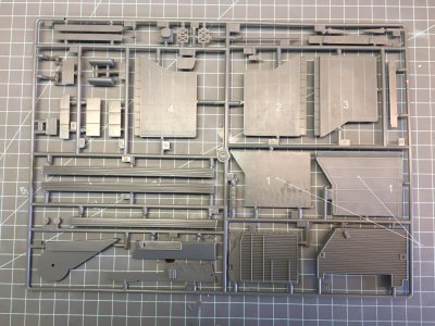 Sprue C
The upper side of the kit elevators, the arrows point to the 2 kit parts for Elevator 1. These are the parts you will work with.
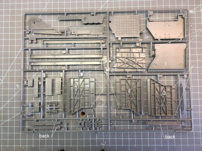
The underside of the 4 elevators. The arrows point to the 8 openings in the sides.
On the model I intend to have the starboard elevators all up and number 4 on the port side down. Each elevator will be as accurate as I can make it. The elevators in the kit have an approximation of the support structure but if you want to accurize them a good bit of work will be required. The grated deck plates that I purchased from Gold Medal Models are very nicely done. They fit very well. But all of the existing deck on the plastic parts must be removed to use them. The fore and aft beams in the under structure match up with the plating on the Photoetched deck and should be retained but they were on the thin side. The other braces were just not correct.
I determined that the best way to proceed was to use a razor saw, drill and burrs to remove the material and then sand or replace the beams. In the end I only retained one beam out of the 4 elevators. If you just try to thin the deck by sanding it, you will lose some of the vertical height of the elevator, (around .060”) and this will have to be replaced. I did have to sand the molded grating off the elevators. As a result they were not thick enough for the 2 support trusses to fit in the under deck area and I used a .040” X .040” strip between the elevator and the truss to get the spacing right.
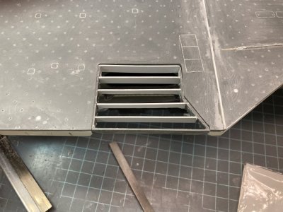
This photo shows Elevator 1 opened up between all the beams and they all have been replaced along with the back wall. The side gaps are also filled. It is dry fitted to the opening. So far, so good.
The elevators all need to have the inside or rear wall added except Elevator 1. It is a separate “L” shaped part for 2 thru 4, but is part of the insert for Elevator 1. For the other 3 it adds more material just under the deck that must be removed. It is also too wide because of the kits mounting system. There is a portion of the outer fore and aft wall (side wall) that is cut away on both sides of each elevator between the rear wall and the last beam on the kit parts. I could not find any photographic evidence of this gap. My research shows this to be solid like the rest of the outer frame. I used scrap plastic to fill this on all the elevators. 8 patches total. On Elevator 1 the under structure is a separate part. I was going to glue this in place and then treat it like the other three elevators but the 4 beams don’t fit tightly. They didn’t touch the side walls. I ended up cutting the deck away and replacing all the beams. I used the photoetched deck to get them located right.
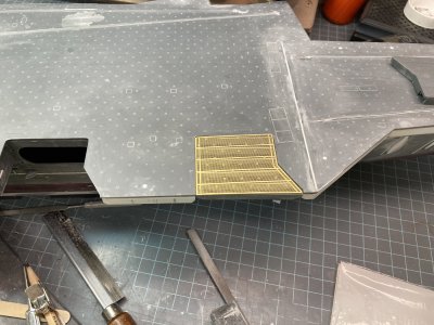
Here I have checked the fit of the deck plate to the opening.
The Tamiya kit has elevator 1 molded in place with the flight deck. In this case I was glad that I had the MHM kit vice the Tamiya. All of the Tamiya elevators have a separate structural part that is glued to the underside of each elevator. I just had to deal with it on Elevator 1. The separate structure is molded on a flat plate that would make twice the thickness of deck to remove. I read an article and saw some in progress photos where a modeler drilled out, filed and sanded to remove all the plate material just leaving the structural parts. It is a lot of additional work and most of the structure isn’t correct anyway. He also used the photo etched deck. He had to remove the entire deck surface of the elevator too. It would be difficult to use the photoetch grates on elevator 1 of the Tamiya kit without removing it from the flight deck. If you leave it in place you will have to remove material from the deck side to compensate for the thickness of the photoetch. It doesn’t make much sense for Tamiya to have just one elevator molded in place with the flight deck.
With Elevator 1’s deck removed and new transverse beams in place I checked the fit to the flight deck and the fit of the photoetched deck to the elevator which was pretty good. A small strip must be added to the angled section and another to the inside edge of the elevator opening for a perfect fit. I wanted to add the X shaped cross brace that I could see in photos and then the Eduard photoetch trusses. Two of the beams have trusses attached which extend past the edges of the elevator frame. These are the supports and connections for the Elevator cables. They are not provided in the kit but the Eduard Set Part 4 has them for all 4 elevators. The cross brace runs between the two beams with the trusses corner to corner. It is a T Beam structural part. It is welded at each corner and where it crosses the two center beams it appears to be cut and welded to each.
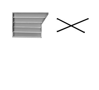
This is the scanned image of Elevator 1 and the drawing of the cross brace I made.
I scanned the underside of the 4 elevators and then drew the cross brace on the scan in Corel. I only kept the drawn part discarding the scan. I printed the drawing on card stock. The Elevators are almost the same except Elevator 4 which is a mirror image of the other 3. Elevator 2 and 3 are virtually identical on the model. In real life none of the elevators is the same, they are distinctly different. My drawing worked for all 4. I put wax paper over this and taped it down. I could lay the plastic strip on the wax paper, tape the pieces over the diagram and glue the individual parts together. On the longest section I used a full length of .015” plastic strip. The remaining legs were two separate pieces. On the upper side (the visible side is the lower or under side) I added a rectangular brace at the cross point. Then on the underside I glued a thin strip to the center of the pieces to represent the T Beam. This time I used a full length piece over the leg with multiple parts and short pieces for the other two. It gave the assembly some strength. I let them dry overnight and I lifted them from the wax paper as an assembly. I made each leg longer than needed to make sure I got a good fit. I even remembered to make the Elevator 4 brace as a mirror image of the other 3.
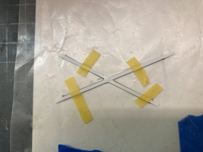
This is the beginning of the assembly.
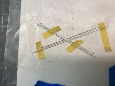
I have added the thinner strip and assembled one of the cross braces.
I removed the first 2 Eduard parts from the fret to make the outer truss on Elevator 1. This will be glued to the bottom of the elevator at the first transverse beam inboard of the outer plate. Assembly was extremely fiddly and using CA would get it together only to have it break at the slightest twinge. I decided to remove all the CA and solder it together. It took a very frustrating hour to do this. I would have gotten better with the soldering but when I put it in position on the elevator, it didn’t extend past the edges like it should! I rechecked that I used the right parts and followed the instructions correctly but Eduard made it wrong.
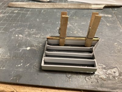
The assembled truss isn’t wide enough.
Well that is to say they made it to fit on the Tamiya model with the sides of the under deck up against the elevator on a part molded with the flight deck. I had cut the under deck area back to be more accurate on my model and my elevator was already a separate part. I only wish I had known about the Eduard parts before I put the truss together. If they had made the parts true to real life they wouldn’t have fit on 1 without some serious modifications (which I had already made). They made a call to make the parts fit the model with no modifications. Yet on Elevator 4 Eduard has you cut back the under deck structure and the beams are the correct width. The remaining trusses are correct but I was a bit disgruntled over Elevator 1 and did not use the Eduard parts except as templates. If I had used the photoetch for the other elevators it would look too different from Elevator 1. The Eduard photoetch is designed to have elevators 2 and 3 down and 1 and 4 up. They provide side skirts with up locks for Elevator 2 and 3 but none for the others.
On Elevator 1 I made these trusses out of plastic strip. I fit the elevator to the flight deck attached to the hull to get the width right. Rather than mess with the photoetch for the two inner trusses, (which fit poorly anyways). The kit parts have a cut out on the underside which the Eduard parts are supposed to follow. I just went ahead and made these from plastic as well. This turned out to be a good decision since I had to modify both of these to fit over the cross brace. It was markedly easier to assemble too.
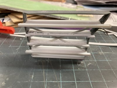
The trusses have been cut out and glued in place. Note the inner center truss has the .010” X .060” strip and the outer hasn’t been fitted yet.
You could buy a 3-D printed set to avoid all this. 3D Wild makes one for $75.00. They have separate sets for the Tamiya and MHM kits. Both include the elevators, accurate closed doors, elevator door wells, elevator guides and 2 sets of side skirts for lowered elevators. There is no deck plating so you would also need a set of the Gold Medal photoetch or make your own somehow. The parts are not 100% accurate as far as the bracing goes and Elevator 1 has the same problem with the two trusses not being wide enough as the Eduard photoetch set. I did not find another supplier. Below is a link to the page if you would like to see it.

I made the trusses for the two support beams just like the Eduard parts using them as templates to get the sizes right. A .040”X.080” beam was wrapped with .010” X .060” strip on the bottom, ends and then HO Scale 1X6 strip on top. This is heavier than the Eduard parts but it matches the elevator beams I made. These were glued to the bottom of the elevator with the smaller strip up. Various sized strip was used to detail the parts. The two inner beams were done in a similar way using the Eduard parts with the curved outer edge for a template. These only received the .010” X .060” strip on the bottom. They were glued to the center beams. When I added center beams I made them straight across, when I added the curved portions it was easier to mate them up. The 2 center beams are a solid part on the real elevators. Notches were cut for the cross brace and then the 2 parts were glued together. Some filling and sanding was required on the beam faces around the cross brace.
I used the Eduard parts meant to detail Elevator 2’s forward and aft frames as a drilling template for the lightening holes on the sides of all the elevators. This worked well but you need to make sure you drill inboard and outboard of the beams. Don’t just place the template and start drilling. There is also a row of openings just under the top edge of the deck. They are represented on the Eduard piece but aren’t open. I cut down the plastic between the transverse beams on the side walls. I used some vertical ladder material from Tom’s Modelworks to frame the openings. Then I added a piece of strip to reinforce the photoetch at the top. You can see these drains looking up at the model with the elevator raised.
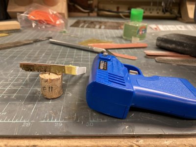
I am ready to drill out the first set of lightening holes using my makeshift guide.
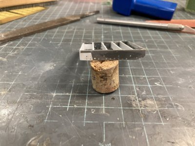
This is the result.
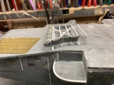
Here all the drain openings are framed with the photoetched ladder material.
Now I have capped the openings with strip to give the ladder more support.
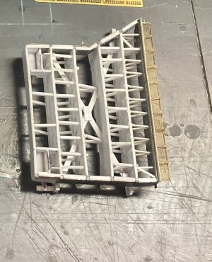
The bisecting frame I made in 3 parts rather than trying to notch the beam that was already in position. This angles up like the sides and has the lightening holes also. I made it only as high as the upper “window” drain holes. Then I made all the bracing between the beams. This is very time consuming because in just the first space there are 46 pieces making up the frames and only 9 are longer than a ¼ inch. The first beam on elevator 1 forms a trapezoid with the front plate so each frame part is a different size. The end result looks good though. I moved on to the next row verifying with reference photos before I made a part. The second row is slightly complicated by the x brace. The third row has only two braces and the fourth is a repeat of the second minus 2 struts. As you add all these struts the elevator frame becomes a nice firm piece.
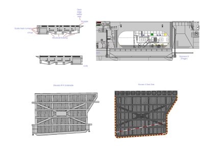
This is what I originally drew for elevator 4. Looking at the framework you will find several things where I diverged from this drawing especially in the guide rollers.
The final space is completely different to account for the part that slides in the guide rails. There is a relatively involved structure to duplicate. I have a few photos of the real elevators but only one which shows this area. The photo turned out to be from the Nimitz or at least a Nimitz class ship. Many of the details are different from Enterprise. The support trusses are a giveaway because they have the cut out like the two inner trusses on the Enterprise elevators. So in this area I used calibrated eyeballs, imagination and guess work. The version in my drawings is close but I drew them with 2 guide rollers on each side which is wrong there should only be the lower one. I didn’t have any interior bracing like on the Nimitz. So I co-opted details from the photo. There is an angled plate that is about ¼ of the width of the beam. It starts below the height of the elevator frame and matches up to the rear truss which supports the guide rollers. This is held off of the truss beam by a vertical metal plate and a strut. On the inner side there is a curved fillet plate that fairs the assembly to the back wall. There are 4 additional struts to support the inside wall.
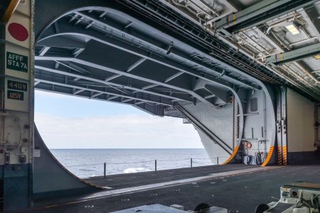
This shows the inboard edge of an elevator showing the supports for the roller guides. It is actually a Nimitz class ship but it gives you an idea of the structure.
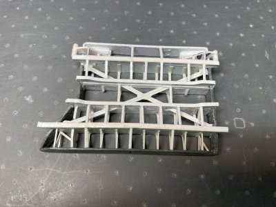
This is Elevator 1 with all frames finished.
The kit elevator guides are incorrect because the slot the elevator slides in is on the side of the guides instead of the outboard face. Some carriers do have a side slot but not Enterprise. This is primarily for an operating feature on the model that lets you position the elevators as you wish. There is a tab that sticks out of the back wall on each side. Once the kit guides are in place on the model and before the flight deck is glued on you slide the tabs for elevators 1 thru 4 (2 thru 4 on the Tamiya kit) into the guides, and cement the flight deck in place trapping them in the guides. I replaced the guides with an aftermarket set and removed the tabs on the back plates of each elevator. Both kits have this feature.
These are the guides for Elevator 1.
Years ago when I was shopping for detail parts I found a Shapeways product that replaced the kit elevator guides. They were made of a hard clear resin like the mooring bits. The nice thing about this resin is it reacts to Micro Weld brand glue so you don’t need CA. I do not remember which seller made these but they don’t seem to be available anymore. You can buy the 3D Wild set of Elevator guides separately for $15.00. Those sets are different for the Tamiya or the MHM kits because the mounting pins are not the same. Make sure you buy the right one if you get these. Since my resin set was for the Tamiya kit the mounting posts wouldn’t work except on the part for elevator 4. I removed all the pins on the starboard guides and filled all the mounting holes on the hull. Then the guides were glued in position on all four elevators. I needed these located to make sure that the guides lined up with the guide rollers on the elevators.
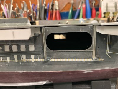
 Hull 044.jpg
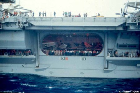
View of Elevator 2 in 1978.
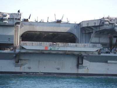
View of Elevator 2 in 2012. This is the version represented by Eduard. But it isn’t correct for the 1980’s or prior.
Sorry I ran out of space for photos so I will continue this in a second post.
It has been some 42 days since my last post and I know that I didn’t work every day so say 38 days at around 3 hours per day would mean I spent around 114 hours making the 4 elevators. Because of the number of photos that I want to attach I may have to break this into 2 posts.
On the ship each elevator is approximately 4000 square feet. They are capable of lifting two aircraft weighing up to 100,000 pounds each. The elevators are vital to operations on any aircraft carrier. The Enterprise, Forrestal, Kitty Hawk and Nimitz Classes all have 4 elevators but the Gerald R Ford Class has only 3 so any one going out of operation would seriously hamper the ships ability to function. I saw Elevator 2 jam a couple of times during the 1978 deployment. They had to rock the controls from up to down repeatedly to un-stick it. This is one reason why it was partially plated over during the major refit that followed that deployment. The plating was to keep the giant platform from flexing and locking up in the guides. They plated over the drain holes under the deck by 2012 which is an indicator that the deck was solid by that time too. I am sure that all 4 elevators were completely plated over sometime during the final 12 years of service. I believe the Enterprise was unique in having grated elevators. I never served on another carrier with them nor heard of one. I imagine it was tried for its ability to shed water quickly, weight and/or cost reduction.

In this photo from the decommissioning in 2012 you can see that the drain holes are plated over. Compare that side view to the one below.

The drain holes are open in this photo of Elevator 2 in the 80’s. Coupled with the grated deck the elevators could shed water quickly. Note the cable attachment points.
The actual elevators have a 5 sided exterior frame. It slopes up at the outboard edge and on the outboard plate. There are 4 inner transverse beams. Two of these have a support truss attached on the bottom while the two center beams have a curved cut out center section. I am not sure but I think the ends of these are part of the locking device. On the side of the elevator with the angled extension there is a frame that goes from that side straight forward to the outside wall bisecting the extension. There is a cross brace to strengthen the framework and a number of struts to brace everything else. There are drain holes just under the deck and lightening holes along each side. The sides on the inboard edge have a piston that rides in the elevator guide track.

This photo of Elevator 1 from the same time as the one above shows the construction of the support system very well. The white arrows are pointing to the bisecting frame.
I have a couple of stories that involve the elevators. The first involves my wildest elevator ride. It was not unusual to ride an elevator up or down if you were moving heavy equipment and you were riding with it. If you were riding brakes in a plane going up or down you stayed in the cockpit while they ran the elevator. The ride I’m thinking about occurred on the morning of 2 October, 1976 at Latitude 000 degrees, 00 minutes and East Longitude 141 degrees 15 minutes. On this day I was inducted into the hallowed ranks of Trusty Shellbacks.
We rode up to the flight deck on Elevator 2 but in order to get there we had many hurdles to cross. We were rousted out in the dark. I worked nights so I was already up but it was dark when the festivities began. The Trusty Shellbacks who took us in charge saw to it that we were properly attired. Dungaree pants inside out and backwards. A ”T” shirt inside out and backwards with a 12 inch P stenciled on the front and back and a set of underwear also inside out and backwards, stenciled with a P, worn over the dungarees. To promote good order and discipline wherever we travelled we did so on our hands and knees probably so we could be swatted more easily with all those shillelaghs (worn out canvas fire hose jackets). We got to experience all the culinary delights of Pollywog Breakfast. After that we waited in the shop and had many fine adventures courtesy of the illustrious Shellbacks in our squadron. When our division was finally called away we crawled to the hanger and then to Elevator 2.
We were placed face down on the elevator. I have no idea how many of us but at least a couple hundred. The Shellbacks kept popping their shillelaghs but left us alone on the elevator (I wonder why). Whenever the elevators travel, they sound a klaxon horn (it makes that ah-ooga, ah-ooga sound) a warning to anybody nearby. Up we went only to be hit with several streams from salt water fire hoses as we rode up. I remember grabbing that grated deck and hanging on for dear life because it felt like I was going to be flushed overboard. There was a ring of Shellbacks screaming and waving shillelaghs at the top of the elevator opening. I actually felt a glimmer of fear.

The moment I met the Royal Baby, there were so many Pollywogs we had 3 Royal Babies. I gave my camera to one of the Shellbacks and he caught this for me. In the background to the right is the Royal Court.
The rest of the morning was spent crawling around the flight deck making manners with Neptune’s Royal Court, the Royal Baby, the Royal Dentist, the Royal Barber and the Royal Devil. Then there were pleasant interludes in the chute, the stocks and finally the tank. I thought I would never be clean again. I am glad that I went through it though. It wasn’t mandatory just a bit of fun at the Pollywogs expense. They ran the elevator repeatedly to cycle all the Pollywogs through initiation. They went by division and there were 61 divisions if I counted right. I later heard that over 60% or around 3500 of the crew were Pollywogs.

My Shellback Certificate from 1976.
We were in the infancy of the Naval Aviation Tool Control Program in 1976. Tool control is being able to account for your tools 100% of the time. It was a spin-off of the FOD ( Foreign Object Damage specifically damage to engines,)reduction program. It was drummed into us that a lost tool could potentially destroy an aircraft engine or become a missile when blown by aircraft exhausts. Heaven forbid you lose a tool in the cockpit. When I reported to the squadron in June of 1975 there really wasn’t much of a program compared to what it became later. It was just assumed that you would take care of your tools because you were told to. One of the first things that happened after checking in was to go to the tool room and get issued tools. The tool room was simply a room with a lot of tools in it. Nobody worked in the tool room that I knew of and anybody could go in and get anything they needed within limits. I’m sure someone was in charge but it wasn’t obvious. The only restriction was that you had to go to Maintenance Control and check out the key and they did not just hand it out. There had to be a valid reason. The checkout/in was logged but records of what you took were on you.
Three of us IWT technicians reported aboard at the same time and one of the Second Class Petty officers in the shop took us around the squadron. One stop was the tool storage room. We were directed to take one of the tool boxes, a box much like my father’s fishing tackle box. The lid opened in the center and as it opened 2 levels of trays opened with it. It was well used but sound. It was painted Royal Mace Green, the squadron color, and stenciled with yellow shop and squadron markings. Primary storage was a large space in the bottom of the box. The petty officer with us went through the bins and selected what tools we would need. But when we were done he entertained requests for other items like hacksaws and hand drills (the old fashioned hand cranked kind, In Naval slang a Hurdy Gurdy).
Back in the shop we used a paper form to record all of the tools in our new boxes. If you weren’t honest you could get away with some swag here. Nobody checked my inventory when I was done. This went in a document protector and was kept in the box. A copy went to the shop supervisor to be filed away. We were told to inventory the boxes contents once a quarter. We were also told that all of these tools were our responsibility and when we left the squadron they would all be inventoried and returned to the tool room. Any discrepancies would be deducted from our pay. I didn’t make much back then so the thought of losing any of my pay did not sit well with me. It made more sense to me to inventory my tools every day.
All of the tools were placed in the box as we liked but there was no organization other than the trays were convenient for small tools like pin extractors and socket wrenches everything else went in the bottom. I probably had 50 tools and consumables in my box. I also had a lock and key to keep it secure, a carpenter’s leather tool pouch with a web belt and nylon bag/cover to keep everything in the pouch, two kinds of safety wire, two kinds of electricians tape, a TL-29 Electricians knife with a belt pouch and a Navy flashlight also with a belt holder. That was in 1975. Despite the lack of organization I never lost a tool.
By 1976 things were changing. The shop received a wall tool box and 4 aluminum attaché cases. We also received layered foam sheets to organize the tools in the cases. Every shop in the squadron was doing this locally but it was a navy wide change. Each tool would have a cut out where only it could go. Ideally the cut out was colored to highlight a missing tool (shadowed). At a glance you could tell if everything was where it was supposed to be. The tools we had in the boxes were reduced to the minimum as determined by us. Any tools that didn’t make the cut for the attaché cases and couldn’t be stored in the wall box were turned in. I said goodbye to my green tackle box. These new boxes were inventoried at every shift change and after every job you went out on. Nobody had their own set of tools any more.
New tool pouches were designed by our supervisor. He did a pretty fair job with the pouches and we all collaborated on what was essential to put in them. He did the lay out and worked with the squadron PR (Parachute Rigger) who would sew the pouches up for us. Now every shop in the squadron was doing this too so the Rigger was pretty busy, he still had his regular work to keep up with too. The boss designed a pouch of heavy canvas, double stitched with nylon covered hems. It had 2 rows of slots separated by a central space and covered by a Velcro closed flap. There was a secure pocket to hold the speed wrench located on the outer panel and a built in flash light holder.
The central space could hold the inventory form and consumables for whatever job you were going out on. The inner side was conventional but (here’s that fatal but) the outer panel was held closed by more Velcro down the sides. He had it made this way so at the end of the job you could open the whole thing up and clean any bits of safety wire, hardware and other debris, leaving the pouch clean for the next job. But when opened, the outer row of tools was now pointing down if you were wearing it! This was okay in the shop but not so much if you were wearing the pouch on deck. When the pouches were new the tool slots were tight but they soon loosened up with use.
Velcro is pretty good stuff but after it is used extensively it gets weak and can disconnect pretty easily. We were quick to point out that while the ease which the pouch could be cleaned was nice, the fact that the thing could pop open on deck and drop tools everywhere might be asking for trouble. We wanted the pouch sides sewed up but the PR was buried in work and would not be able to do this job for a while. The boss did not believe it would ever pop open. We had to use those pouches for almost a month and don’t get me wrong they were miles better than the carpenter’s pouches. You could run down the flight deck and things stayed where they were supposed to. Unfortunately the flight deck is a very dirty place and constantly exposed to the weather so the pouches were soon dirty, oily and damp and this adversely affected the Velcro holding the outer panel closed. The closure for the cover flap held up pretty well but when you opened the flap the outer panel tended to drop open under the weight of the tools on it (remember that speed handle). You had to hold it closed until the flap was secured again.
One fine day I was sent up on deck to work on the RADAR on one of our planes. We were shorthanded and I had to work on the gripe by myself. I took a ladder, a pouch, my flight deck gear and headed up. I found the plane on elevator 1. Usually our aircraft were parked along the bow or in an area called the 6 pack but it was not unheard of to put one on an elevator. I got set up, carefully positioned the ladder, got the radome opened up, located a power cord and got the aircraft powered up with some help from our roving CDI (Collateral Duty Inspector, it takes two people minimum to apply 400hz aircraft power). It was fairly easy to verify the gripe and determine a faulty box and I climbed up on the ladder to remove the defective item. The thing about using a step ladder on the elevators was those grates were just the right size to swallow one of the legs. The legs had rubber blocks to keep them from moving around but shifting your weight could cause one to jerk and slip into a hole.
 Plate 07J Flight Deck Terms
I will probably refer to various parts on the flight deck from time to time so this should help. The Six Pack is just across from the angle forward of the island to the starboard of the foul line. It was called that since you could park six smaller aircraft there say A-4’s or in my case A-7E’s.
I was removing the power supply on the forward RADAR package which required swinging it out to starboard from the nose to access all the plugs and hardware. Disconnecting the cables went well but when I went to the pouch to get a ratchet and socket for the bolts I had one hand on the flap and one hand for the ladder. Out of hands, I was using my body to hold the RADAR package open. The weight shift caused the ladder to shift just as I pulled open the flap on the pouch and the outer panel promptly fell down. All the tools fell out of the slots except the speed wrench, (it was held in its pocket by more Velcro). Tools were hitting the ladder and then the deck with a nice ping pinging sound. Every tool on the outside panel fell through the grates and went to Davy Jones Locker. I sure hope none of the Royal Court got boinked on the head with a tool!
I cursed profoundly but it was done. Everything we complained about had come to pass with a vengeance. I now had to go below and report the loss of all those tools. It was not good. The red tape went on for what seemed like hours. I must have explained what happened 20 times. When it was all said and done new tools got ordered for the pouch and all the tool pouch inner and outer flaps were sewed together pretty quickly but my boss was not happy because I had made him look bad (a major faux pas, the Maintenance Chief did chew on him a bit). I did seem to get a lot of Shore Patrols and late watches in port after that.
The Navy continued to evolve its tool control program. It seemed like there was a change every few months. When I retired, I was in an F/A-18C squadron. The tool boxes and pouches were all specified for each shop. They were laid out identically throughout the Navy. You could go to any other F/A-18 squadron and easily inventory their tools because they were the same as yours. All the tools for all the different aircraft were managed the same way. You checked all tools out from a tool room where someone was in charge. Tools were used for one job then you returned them. The only exceptions were Plane Captains and Troubleshooters who checked out their pouches for the shift. Each tool was etched with the squadron and shop.
You inventoried the box or pouch at check out from the tool room, with your supervisor and a CDI before you went on the job, and reverse the process when you were done. If you should lose a tool on the ship the CAG Maintenance Chief, the squadron Maintenance Chief, your supervisor and Quality Assurance all had to be notified immediately. If the ship was flying, flight ops were suspended until the missing item was found. Ashore, thankfully only your squadron was involved. All hands would search and the person who lost the tool would face disciplinary action. I remember all hands staying late one night at the home station because of a missing tool which was found in a manual marking a page! Missing tools became very rare.
This escalation of rules and regulations was a direct result of the end of the Viet Nam War. During the war you worked hard and on liberty you played hard. Nobody was concerned with much but the mission. Admiral Zumwalt the CNO had relaxed rules regarding civilian clothes, haircut regulations and even beards were permitted. Things were pretty easy as long as you did your job. But the end of the war saw major budget cuts along with a reduction in force. There was more legislative oversight and the draft ended. It was only a matter of time till things tightened up across the board. We saw changes and new regulations frequently during that time period.
 Sprue C
The upper side of the kit elevators, the arrows point to the 2 kit parts for Elevator 1. These are the parts you will work with.

The underside of the 4 elevators. The arrows point to the 8 openings in the sides.
On the model I intend to have the starboard elevators all up and number 4 on the port side down. Each elevator will be as accurate as I can make it. The elevators in the kit have an approximation of the support structure but if you want to accurize them a good bit of work will be required. The grated deck plates that I purchased from Gold Medal Models are very nicely done. They fit very well. But all of the existing deck on the plastic parts must be removed to use them. The fore and aft beams in the under structure match up with the plating on the Photoetched deck and should be retained but they were on the thin side. The other braces were just not correct.
I determined that the best way to proceed was to use a razor saw, drill and burrs to remove the material and then sand or replace the beams. In the end I only retained one beam out of the 4 elevators. If you just try to thin the deck by sanding it, you will lose some of the vertical height of the elevator, (around .060”) and this will have to be replaced. I did have to sand the molded grating off the elevators. As a result they were not thick enough for the 2 support trusses to fit in the under deck area and I used a .040” X .040” strip between the elevator and the truss to get the spacing right.

This photo shows Elevator 1 opened up between all the beams and they all have been replaced along with the back wall. The side gaps are also filled. It is dry fitted to the opening. So far, so good.
The elevators all need to have the inside or rear wall added except Elevator 1. It is a separate “L” shaped part for 2 thru 4, but is part of the insert for Elevator 1. For the other 3 it adds more material just under the deck that must be removed. It is also too wide because of the kits mounting system. There is a portion of the outer fore and aft wall (side wall) that is cut away on both sides of each elevator between the rear wall and the last beam on the kit parts. I could not find any photographic evidence of this gap. My research shows this to be solid like the rest of the outer frame. I used scrap plastic to fill this on all the elevators. 8 patches total. On Elevator 1 the under structure is a separate part. I was going to glue this in place and then treat it like the other three elevators but the 4 beams don’t fit tightly. They didn’t touch the side walls. I ended up cutting the deck away and replacing all the beams. I used the photoetched deck to get them located right.

Here I have checked the fit of the deck plate to the opening.
The Tamiya kit has elevator 1 molded in place with the flight deck. In this case I was glad that I had the MHM kit vice the Tamiya. All of the Tamiya elevators have a separate structural part that is glued to the underside of each elevator. I just had to deal with it on Elevator 1. The separate structure is molded on a flat plate that would make twice the thickness of deck to remove. I read an article and saw some in progress photos where a modeler drilled out, filed and sanded to remove all the plate material just leaving the structural parts. It is a lot of additional work and most of the structure isn’t correct anyway. He also used the photo etched deck. He had to remove the entire deck surface of the elevator too. It would be difficult to use the photoetch grates on elevator 1 of the Tamiya kit without removing it from the flight deck. If you leave it in place you will have to remove material from the deck side to compensate for the thickness of the photoetch. It doesn’t make much sense for Tamiya to have just one elevator molded in place with the flight deck.
With Elevator 1’s deck removed and new transverse beams in place I checked the fit to the flight deck and the fit of the photoetched deck to the elevator which was pretty good. A small strip must be added to the angled section and another to the inside edge of the elevator opening for a perfect fit. I wanted to add the X shaped cross brace that I could see in photos and then the Eduard photoetch trusses. Two of the beams have trusses attached which extend past the edges of the elevator frame. These are the supports and connections for the Elevator cables. They are not provided in the kit but the Eduard Set Part 4 has them for all 4 elevators. The cross brace runs between the two beams with the trusses corner to corner. It is a T Beam structural part. It is welded at each corner and where it crosses the two center beams it appears to be cut and welded to each.

This is the scanned image of Elevator 1 and the drawing of the cross brace I made.
I scanned the underside of the 4 elevators and then drew the cross brace on the scan in Corel. I only kept the drawn part discarding the scan. I printed the drawing on card stock. The Elevators are almost the same except Elevator 4 which is a mirror image of the other 3. Elevator 2 and 3 are virtually identical on the model. In real life none of the elevators is the same, they are distinctly different. My drawing worked for all 4. I put wax paper over this and taped it down. I could lay the plastic strip on the wax paper, tape the pieces over the diagram and glue the individual parts together. On the longest section I used a full length of .015” plastic strip. The remaining legs were two separate pieces. On the upper side (the visible side is the lower or under side) I added a rectangular brace at the cross point. Then on the underside I glued a thin strip to the center of the pieces to represent the T Beam. This time I used a full length piece over the leg with multiple parts and short pieces for the other two. It gave the assembly some strength. I let them dry overnight and I lifted them from the wax paper as an assembly. I made each leg longer than needed to make sure I got a good fit. I even remembered to make the Elevator 4 brace as a mirror image of the other 3.

This is the beginning of the assembly.

I have added the thinner strip and assembled one of the cross braces.
I removed the first 2 Eduard parts from the fret to make the outer truss on Elevator 1. This will be glued to the bottom of the elevator at the first transverse beam inboard of the outer plate. Assembly was extremely fiddly and using CA would get it together only to have it break at the slightest twinge. I decided to remove all the CA and solder it together. It took a very frustrating hour to do this. I would have gotten better with the soldering but when I put it in position on the elevator, it didn’t extend past the edges like it should! I rechecked that I used the right parts and followed the instructions correctly but Eduard made it wrong.

The assembled truss isn’t wide enough.
Well that is to say they made it to fit on the Tamiya model with the sides of the under deck up against the elevator on a part molded with the flight deck. I had cut the under deck area back to be more accurate on my model and my elevator was already a separate part. I only wish I had known about the Eduard parts before I put the truss together. If they had made the parts true to real life they wouldn’t have fit on 1 without some serious modifications (which I had already made). They made a call to make the parts fit the model with no modifications. Yet on Elevator 4 Eduard has you cut back the under deck structure and the beams are the correct width. The remaining trusses are correct but I was a bit disgruntled over Elevator 1 and did not use the Eduard parts except as templates. If I had used the photoetch for the other elevators it would look too different from Elevator 1. The Eduard photoetch is designed to have elevators 2 and 3 down and 1 and 4 up. They provide side skirts with up locks for Elevator 2 and 3 but none for the others.
On Elevator 1 I made these trusses out of plastic strip. I fit the elevator to the flight deck attached to the hull to get the width right. Rather than mess with the photoetch for the two inner trusses, (which fit poorly anyways). The kit parts have a cut out on the underside which the Eduard parts are supposed to follow. I just went ahead and made these from plastic as well. This turned out to be a good decision since I had to modify both of these to fit over the cross brace. It was markedly easier to assemble too.

The trusses have been cut out and glued in place. Note the inner center truss has the .010” X .060” strip and the outer hasn’t been fitted yet.
You could buy a 3-D printed set to avoid all this. 3D Wild makes one for $75.00. They have separate sets for the Tamiya and MHM kits. Both include the elevators, accurate closed doors, elevator door wells, elevator guides and 2 sets of side skirts for lowered elevators. There is no deck plating so you would also need a set of the Gold Medal photoetch or make your own somehow. The parts are not 100% accurate as far as the bracing goes and Elevator 1 has the same problem with the two trusses not being wide enough as the Eduard photoetch set. I did not find another supplier. Below is a link to the page if you would like to see it.

Big E Elevator Set Tam
1:350 Scale for the 1:350 CVN-65 Enterprise Aircraft Carrier model kit. This model kit is designed by Small Designer (Belgium) and manufactured/distributed by 3D-WILD (USA).
3d-wild.com
I made the trusses for the two support beams just like the Eduard parts using them as templates to get the sizes right. A .040”X.080” beam was wrapped with .010” X .060” strip on the bottom, ends and then HO Scale 1X6 strip on top. This is heavier than the Eduard parts but it matches the elevator beams I made. These were glued to the bottom of the elevator with the smaller strip up. Various sized strip was used to detail the parts. The two inner beams were done in a similar way using the Eduard parts with the curved outer edge for a template. These only received the .010” X .060” strip on the bottom. They were glued to the center beams. When I added center beams I made them straight across, when I added the curved portions it was easier to mate them up. The 2 center beams are a solid part on the real elevators. Notches were cut for the cross brace and then the 2 parts were glued together. Some filling and sanding was required on the beam faces around the cross brace.
I used the Eduard parts meant to detail Elevator 2’s forward and aft frames as a drilling template for the lightening holes on the sides of all the elevators. This worked well but you need to make sure you drill inboard and outboard of the beams. Don’t just place the template and start drilling. There is also a row of openings just under the top edge of the deck. They are represented on the Eduard piece but aren’t open. I cut down the plastic between the transverse beams on the side walls. I used some vertical ladder material from Tom’s Modelworks to frame the openings. Then I added a piece of strip to reinforce the photoetch at the top. You can see these drains looking up at the model with the elevator raised.

I am ready to drill out the first set of lightening holes using my makeshift guide.

This is the result.

Here all the drain openings are framed with the photoetched ladder material.

Now I have capped the openings with strip to give the ladder more support.
The bisecting frame I made in 3 parts rather than trying to notch the beam that was already in position. This angles up like the sides and has the lightening holes also. I made it only as high as the upper “window” drain holes. Then I made all the bracing between the beams. This is very time consuming because in just the first space there are 46 pieces making up the frames and only 9 are longer than a ¼ inch. The first beam on elevator 1 forms a trapezoid with the front plate so each frame part is a different size. The end result looks good though. I moved on to the next row verifying with reference photos before I made a part. The second row is slightly complicated by the x brace. The third row has only two braces and the fourth is a repeat of the second minus 2 struts. As you add all these struts the elevator frame becomes a nice firm piece.

This is what I originally drew for elevator 4. Looking at the framework you will find several things where I diverged from this drawing especially in the guide rollers.
The final space is completely different to account for the part that slides in the guide rails. There is a relatively involved structure to duplicate. I have a few photos of the real elevators but only one which shows this area. The photo turned out to be from the Nimitz or at least a Nimitz class ship. Many of the details are different from Enterprise. The support trusses are a giveaway because they have the cut out like the two inner trusses on the Enterprise elevators. So in this area I used calibrated eyeballs, imagination and guess work. The version in my drawings is close but I drew them with 2 guide rollers on each side which is wrong there should only be the lower one. I didn’t have any interior bracing like on the Nimitz. So I co-opted details from the photo. There is an angled plate that is about ¼ of the width of the beam. It starts below the height of the elevator frame and matches up to the rear truss which supports the guide rollers. This is held off of the truss beam by a vertical metal plate and a strut. On the inner side there is a curved fillet plate that fairs the assembly to the back wall. There are 4 additional struts to support the inside wall.

This shows the inboard edge of an elevator showing the supports for the roller guides. It is actually a Nimitz class ship but it gives you an idea of the structure.

This is Elevator 1 with all frames finished.
The kit elevator guides are incorrect because the slot the elevator slides in is on the side of the guides instead of the outboard face. Some carriers do have a side slot but not Enterprise. This is primarily for an operating feature on the model that lets you position the elevators as you wish. There is a tab that sticks out of the back wall on each side. Once the kit guides are in place on the model and before the flight deck is glued on you slide the tabs for elevators 1 thru 4 (2 thru 4 on the Tamiya kit) into the guides, and cement the flight deck in place trapping them in the guides. I replaced the guides with an aftermarket set and removed the tabs on the back plates of each elevator. Both kits have this feature.

These are the guides for Elevator 1.
Years ago when I was shopping for detail parts I found a Shapeways product that replaced the kit elevator guides. They were made of a hard clear resin like the mooring bits. The nice thing about this resin is it reacts to Micro Weld brand glue so you don’t need CA. I do not remember which seller made these but they don’t seem to be available anymore. You can buy the 3D Wild set of Elevator guides separately for $15.00. Those sets are different for the Tamiya or the MHM kits because the mounting pins are not the same. Make sure you buy the right one if you get these. Since my resin set was for the Tamiya kit the mounting posts wouldn’t work except on the part for elevator 4. I removed all the pins on the starboard guides and filled all the mounting holes on the hull. Then the guides were glued in position on all four elevators. I needed these located to make sure that the guides lined up with the guide rollers on the elevators.
 Hull 044.jpg
View of Elevator 2 in 1978.

View of Elevator 2 in 2012. This is the version represented by Eduard. But it isn’t correct for the 1980’s or prior.
Sorry I ran out of space for photos so I will continue this in a second post.
- Joined
- May 8, 2021
- Messages
- 53
- Points
- 78

Continued from previous post. I wanted to use the Eduard photoetch for the outside face. They have some nice parts for this area. There is a coaming at the deck edge which has a lot of nice vertical detail. Unfortunately this detail wasn’t there in my time frame in fact it wasn’t there till the 2000’s. So that part wasn’t used. I made coamings out of plastic strip and detailed it with bits of .010” x .020” strip. Their safety nets are pretty nice but they split them to install bomb disposal ramps. In 1978 there were 5 bomb ramps located at various points over the catwalks. They were only rigged if we were actually carrying ordnance because you had to stoop down and duck under them. When they weren’t deployed they were stored in the catwalks. I first built up Elevator 1 using Eduard’s photoetch but it didn’t look right. More research revealed that it wasn’t right for 1978.
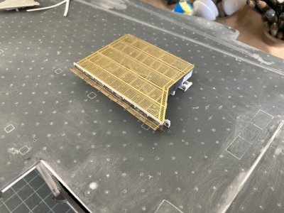
This is my take on the safety nets and coaming on Elevator 1.
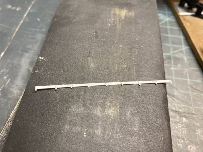
This coaming is assembled and ready to install.
That is probably why they were moved to the elevators at some point. There were two others, one located over the safety nets on the port side round down and another over the nets on the port side angle but none on the elevators. If you were to use the Eduard nets for the elevators there will be a gap in the middle. I had two other sets of photoetch and since the White Ensign nets were closer to the width of the elevators I used theirs. I did mount it like the Eduard nets at an angle and then add braces from the Eduard set. The actual elevator nets were individual nets in series and Eduard is correct in in having pairs of braces together. Since the coaming in 1978 was smooth I made my own using more strip. I had a heck of a time mounting the nets and getting them relatively straight. I tried several ways and I settled on gluing a strip just below where the net will go and using that to locate it. The Eduard set also has 2 small rectangular pieces that are mounted below the nets, but above the angled face and extend past the elevator edges which I did use. I don’t know what these did or what they were called but they were there in the 70’s.
 Flight
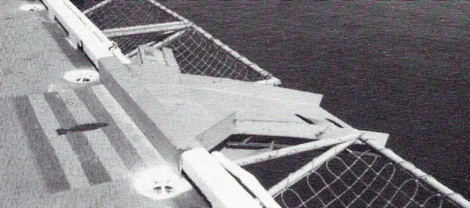
This photo from the 80’s shows the ordnance disposal ramp on the angle. Notice how the nets are rigged.
The nets on the elevators were individual assemblies because sometimes conveyors or brows were rigged to the elevators in port. The nets would interfere with this. You could pull the pins securing the braces and let select nets hang down so they wouldn’t be in the way. The usual manner of mounting the nets horizontally doesn’t look quite right to me. The nets were really steel cable woven into a net and secured at the intersections with swedges, they were laced to the frames with more cable. They sagged in the frames they were not tight. Assembling something to replicate that would be fiddley squared plus.
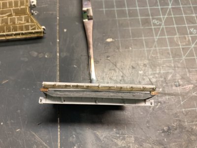
Here is the strip under the net once it is painted it won’t be that visible.
On the trusses for the elevator cables there appear to be 5 cables which are routed through a block of some sort and then are secured to the truss with nuts and washers. I had thought this originally was some kind of multiple pulley block and tackle arrangement but that would mean that each set of elevator cables would have been just one wire. There are 3 cables attached to each outboard edge and 2 inboard. I used a piece of .040” X .060” strip to represent the block. Bits of lead wire are for the 3 cables on the outboard face. I didn’t do the inboard because on the elevators that are up you won’t be able to see them. Then I used punched discs to represent the nuts and washers.
This completed Elevator 1 except for the deck but I did not want to glue it in place till the elevators are painted. Because of all the structural elements it will be easier to paint the elevator from the top and bottom. I’ll paint the underside of the deck with the hull color, allow that to dry and flip it over and paint the deck colors. At this point I am not sure if I will paint the red and yellow warning stripes or use the decals. But doing either will be simplified by keeping the parts separate. Now I just have to repeat this 3 more times.
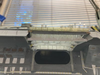
I think this captures the look of the real one.
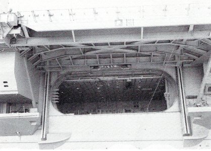 Elevator 01.jpg
The real one in the 80’s.
From Elevator 1 I moved on to 4. It is best to work on one space between frames at a time rather than drilling the entire deck area. This gives the part a bit more rigidity as you begin the filing and sanding process. As I opened up more deck I used wood shims to help support the elevator frame. I used a razor saw to cut through the deck between each beam. Then I drilled the holes at each end joining up the cuts. I used a cutting plier to cut the braces in each section. I could break the piece free opening up the space. I used a drum burr to remove most of the remaining plastic. I looked over the beam and if I damaged it or it appeared too thin I cut it away and glued a .040” strip of the correct height in its place. As I said I only kept one of the original beams.
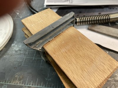
When I was still trying to save the transverse beams this is how I supported them.
Since Elevator 4 will be in the lowered position I wanted to come up with a positive locating feature before I went too far in the construction. I placed it in position and realized that the lip at the hanger deck opening would require some spacers to hold the elevator at the right distance. The Elevator 4 door well has the widest lip of all the elevators. I added blocks of plastic scrap on the backside of the inner wall of the elevator until it was positioned in the right spot. I drilled two .10” holes below the lip through the hull spaced about ¾“ apart. I taped the deck plate in place and then taped the elevator in the down position making sure that the deck was lined up and level with the lip. I used the .10” drill bit to just make an impression of the correct location on the rear wall by twirling it by hand through one of the holes. I removed the elevator and drilled the hole. I then fit a .10” rod onto the elevator. This was glued from the inside. The elevator was placed back on the hull now using the single rod to position it. I taped it again to hold it there and marked the second hole. This was drilled and pinned in the same way. I can place Elevator 4 in position and it matches up perfectly every time.
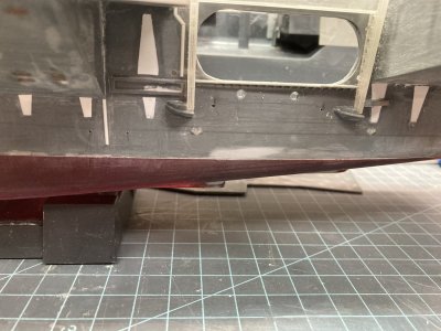
Here I have drilled the mounting holes under the lip.
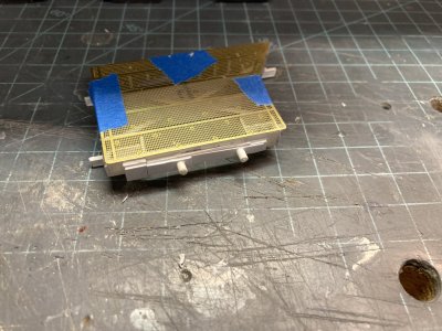
This shows the spacers and pins on the back wall of Elevator 4.
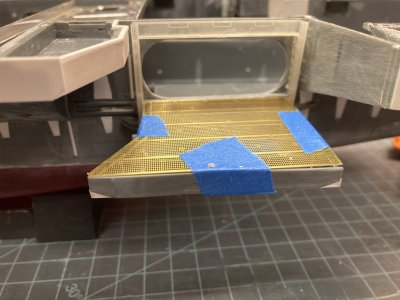
This is Elevator 4 with the deck taped in place and mounted in the lowered position.
Detailing the remaining three elevators was an assembly line process from then on. When I got to a point where one elevator needed glue to set up I simply moved on to the next and brought it up to my latest stopping point. I was able to use a Chopper cutting tool to make several pieces of the same size. It sped things up considerably. I could use the prototype Elevator 1 whenever I had a question about materials or construction. On Elevator 4 when I made up the trusses I had to detail the inner sides since you can see them from above on the starboard side. I also drilled out the cable blocks to accept five wires. On Elevator 2’s deck I decided to use my second set of plates to come up with a fully plated piece for it. Elevator 3 comes closest and it matches up to the padeyes on the flight deck. It took several weeks to put the finishing touches to all the elevators. The results are pretty good in my opinion and it felt like a major item was completed. In order to complete the various sponsons I will need the elevators to determine the location for the slot that the inner truss passes through. When I construct items in the under deck area the elevators will help locate things like the cable reels.
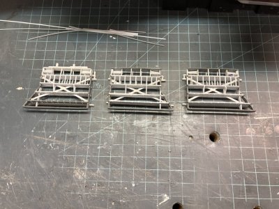
The progress on elevators 2 thru 4.
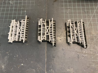
All the framework and bracing is completed on Elevators 2 thru 4.
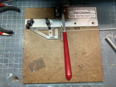
When you have to duplicate several hundred parts this tool is invaluable.
Elevator 4 needed one last detail. If you look at the 80’s side view phot o there is some detail on the ends of the beams that I just didn’t know how to replicate. Nothing I could think of would be fine enough to make raised detail on the ends. I was looking for something else and sumbled on the solution. I found some 1/400 scale railing in my stash. I could cut it up at the posts and…
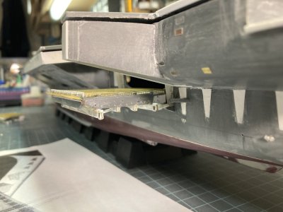
Looking at the ends of the beams on Elevator 4 you can see the result of trimming railing and gluing it on the end plate.
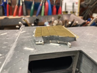
The other side.
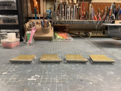
The 4 elevators finished.
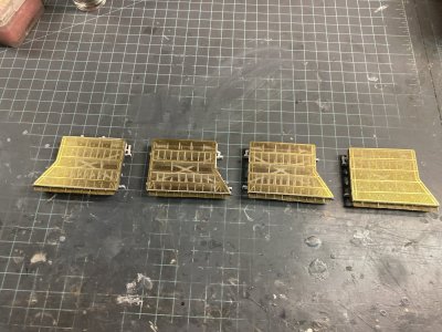
The 4 elevators from above I like the see through effect.
Well that is all for this post I I hope it will be useful for some of you. In the next part I want to work on the hanger deck. I want to get the supports for the hanger in place and then cut out and fit the hanger deck. Until the next time enjoy your modeling.

This is my take on the safety nets and coaming on Elevator 1.

This coaming is assembled and ready to install.
That is probably why they were moved to the elevators at some point. There were two others, one located over the safety nets on the port side round down and another over the nets on the port side angle but none on the elevators. If you were to use the Eduard nets for the elevators there will be a gap in the middle. I had two other sets of photoetch and since the White Ensign nets were closer to the width of the elevators I used theirs. I did mount it like the Eduard nets at an angle and then add braces from the Eduard set. The actual elevator nets were individual nets in series and Eduard is correct in in having pairs of braces together. Since the coaming in 1978 was smooth I made my own using more strip. I had a heck of a time mounting the nets and getting them relatively straight. I tried several ways and I settled on gluing a strip just below where the net will go and using that to locate it. The Eduard set also has 2 small rectangular pieces that are mounted below the nets, but above the angled face and extend past the elevator edges which I did use. I don’t know what these did or what they were called but they were there in the 70’s.
 Flight
This photo from the 80’s shows the ordnance disposal ramp on the angle. Notice how the nets are rigged.
The nets on the elevators were individual assemblies because sometimes conveyors or brows were rigged to the elevators in port. The nets would interfere with this. You could pull the pins securing the braces and let select nets hang down so they wouldn’t be in the way. The usual manner of mounting the nets horizontally doesn’t look quite right to me. The nets were really steel cable woven into a net and secured at the intersections with swedges, they were laced to the frames with more cable. They sagged in the frames they were not tight. Assembling something to replicate that would be fiddley squared plus.

Here is the strip under the net once it is painted it won’t be that visible.
On the trusses for the elevator cables there appear to be 5 cables which are routed through a block of some sort and then are secured to the truss with nuts and washers. I had thought this originally was some kind of multiple pulley block and tackle arrangement but that would mean that each set of elevator cables would have been just one wire. There are 3 cables attached to each outboard edge and 2 inboard. I used a piece of .040” X .060” strip to represent the block. Bits of lead wire are for the 3 cables on the outboard face. I didn’t do the inboard because on the elevators that are up you won’t be able to see them. Then I used punched discs to represent the nuts and washers.
This completed Elevator 1 except for the deck but I did not want to glue it in place till the elevators are painted. Because of all the structural elements it will be easier to paint the elevator from the top and bottom. I’ll paint the underside of the deck with the hull color, allow that to dry and flip it over and paint the deck colors. At this point I am not sure if I will paint the red and yellow warning stripes or use the decals. But doing either will be simplified by keeping the parts separate. Now I just have to repeat this 3 more times.

I think this captures the look of the real one.
 Elevator 01.jpg
The real one in the 80’s.
From Elevator 1 I moved on to 4. It is best to work on one space between frames at a time rather than drilling the entire deck area. This gives the part a bit more rigidity as you begin the filing and sanding process. As I opened up more deck I used wood shims to help support the elevator frame. I used a razor saw to cut through the deck between each beam. Then I drilled the holes at each end joining up the cuts. I used a cutting plier to cut the braces in each section. I could break the piece free opening up the space. I used a drum burr to remove most of the remaining plastic. I looked over the beam and if I damaged it or it appeared too thin I cut it away and glued a .040” strip of the correct height in its place. As I said I only kept one of the original beams.

When I was still trying to save the transverse beams this is how I supported them.
Since Elevator 4 will be in the lowered position I wanted to come up with a positive locating feature before I went too far in the construction. I placed it in position and realized that the lip at the hanger deck opening would require some spacers to hold the elevator at the right distance. The Elevator 4 door well has the widest lip of all the elevators. I added blocks of plastic scrap on the backside of the inner wall of the elevator until it was positioned in the right spot. I drilled two .10” holes below the lip through the hull spaced about ¾“ apart. I taped the deck plate in place and then taped the elevator in the down position making sure that the deck was lined up and level with the lip. I used the .10” drill bit to just make an impression of the correct location on the rear wall by twirling it by hand through one of the holes. I removed the elevator and drilled the hole. I then fit a .10” rod onto the elevator. This was glued from the inside. The elevator was placed back on the hull now using the single rod to position it. I taped it again to hold it there and marked the second hole. This was drilled and pinned in the same way. I can place Elevator 4 in position and it matches up perfectly every time.

Here I have drilled the mounting holes under the lip.

This shows the spacers and pins on the back wall of Elevator 4.

This is Elevator 4 with the deck taped in place and mounted in the lowered position.
Detailing the remaining three elevators was an assembly line process from then on. When I got to a point where one elevator needed glue to set up I simply moved on to the next and brought it up to my latest stopping point. I was able to use a Chopper cutting tool to make several pieces of the same size. It sped things up considerably. I could use the prototype Elevator 1 whenever I had a question about materials or construction. On Elevator 4 when I made up the trusses I had to detail the inner sides since you can see them from above on the starboard side. I also drilled out the cable blocks to accept five wires. On Elevator 2’s deck I decided to use my second set of plates to come up with a fully plated piece for it. Elevator 3 comes closest and it matches up to the padeyes on the flight deck. It took several weeks to put the finishing touches to all the elevators. The results are pretty good in my opinion and it felt like a major item was completed. In order to complete the various sponsons I will need the elevators to determine the location for the slot that the inner truss passes through. When I construct items in the under deck area the elevators will help locate things like the cable reels.

The progress on elevators 2 thru 4.

All the framework and bracing is completed on Elevators 2 thru 4.

When you have to duplicate several hundred parts this tool is invaluable.
Elevator 4 needed one last detail. If you look at the 80’s side view phot o there is some detail on the ends of the beams that I just didn’t know how to replicate. Nothing I could think of would be fine enough to make raised detail on the ends. I was looking for something else and sumbled on the solution. I found some 1/400 scale railing in my stash. I could cut it up at the posts and…

Looking at the ends of the beams on Elevator 4 you can see the result of trimming railing and gluing it on the end plate.

The other side.

The 4 elevators finished.

The 4 elevators from above I like the see through effect.
Well that is all for this post I I hope it will be useful for some of you. In the next part I want to work on the hanger deck. I want to get the supports for the hanger in place and then cut out and fit the hanger deck. Until the next time enjoy your modeling.
Very Impressive!
- Joined
- May 8, 2021
- Messages
- 53
- Points
- 78

Thanks, I appreciate the comment.Very Impressive!
I really like the see-through elevators!
- Joined
- May 8, 2021
- Messages
- 53
- Points
- 78

I really like the see-through elevators!
They were a lot of work but the real thing was really something. Thanks for the comment.I really like the see-through elevators!
- Joined
- May 8, 2021
- Messages
- 53
- Points
- 78

Part 8 The Hanger Deck
In this part I document my build-up of the hanger deck. I had to make 4 separate posts to accommodate all the photos and additional information.
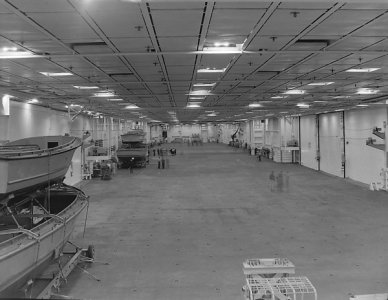
This appears to be some sort of time lapse of the hanger note the group of people to the right which are faded out. It was taken in front of the Power Plants shop facing forward. All the elevator doors are closed. The forward end is in its original configuration before the addition of the overhanging shops. All the way forward the roll-up doors to the left are the GSE shops. Just off the centerline is the entrance to the tunnel and the forward weapons elevator trunk is to the right. You are looking through the divisional doors at the backside of the bulkheads that cover them. The aft weapons elevators are to the right just forward of elevator door # 3 on the right. Elevator door # 4 is on the left.
The hanger bay of the Enterprise was a cavernous area divided into two sections. It was 25’ high X 96’ wide (at the widest point) X 732’ long (.85” X 3.3” X 25.1” in 1/350 Scale). It began at frame 62, the divisional doors were at frame 153 and it ended at frame 242. It could house at least 1/3rd of the air wing or about 32 aircraft for CVW-14. At sea, deployed it was a noisy, chaotic scene of maintenance activity 24/7 for the entire deployment unless we were in a liberty port. Then a handful of aircraft were cleaned up and placed in the hanger as a display and all the others were crammed onto the flight deck. They did this in ports where visitors were permitted aboard to allow foot traffic with minimum peril from tie down chains and sharp surfaces. Usually they all went to the bow and guests were discouraged from walking around them.
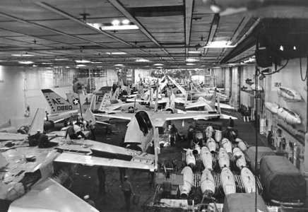
View of the hanger in the late 60’s or early 70’s. Note how the aircraft are stacked in here and there is very little space remaining.
This movement was usually preceded by a flight deck and hanger deck scrub down of epic proportions. Zamboni scrubbers were not in use at the time so it was all done by massive working parties. Each division provided bodies. We manned salt water fire hoses and stiff bristled brooms. First we cleaned the stern then all the aircraft would be moved aft and we scrubbed the forward flight deck. At the same time the hanger would be undergoing the same treatment. If the port was important signal flags would be hung from the overhead.
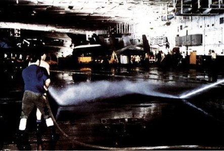
Hanger deck Scrubbex in progress. This is from the 80’s but apparently they didn’t have a Zamboni yet.
The hanger housed a large inventory of GSE (Ground Support Equipment), numerous spare engines in cans, large parts for the catapults and arresting gear, any other material that couldn’t be stored somewhere else and the ships liberty boats Including the Captain’s Gig and the Admiral’s Barge. Even the overhead was used for storage with aircraft drop tanks located in racks. After the rework following this deployment racks were added for arresting gear cables in crates in the door well openings. During my time they were hung on the bulkheads wrapped in plastic. In a holdover from the Vietnam War the bulkheads were festooned with hooks which could take MER/TER bomb racks and launchers that the squadrons or weapons couldn’t store. These were now turned over to Weapons Department at the beginning of a deployment and kept in their spaces and the hooks were used for other things.
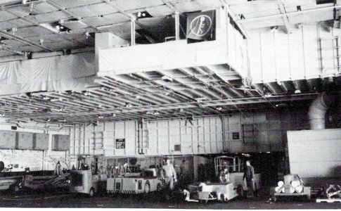
This is the GSE area in the early 80’s after the rework that changed the island. On the overhang at the 02 level the vans are not installed. The openings are the forward entrance to the vans.
Although I never saw a movie on the hanger deck of the Enterprise there was a projection booth on the port side of the hanger. KENT TV the Enterprise’s CC station played several movies each day and they could be viewed on any television connected to the system. Basketball hoops could be swung down for sporting events. They had a boxing ring that could be set up for smokers. There was a stage that could be set up for USO shows which usually occurred at least once during a deployment. Any free space was used by joggers, guys jumping rope, martial arts and there was even a group of cyclists who would set up their bicycles on stands and ride in place. The hanger was used for formations for various divisional/departmental quarters, award ceremonies or inspections. The MARDET (Marine Detachment) used the hanger for PT, close order drill and weapons inspection.
In this photo from one of the cruisebooks a basketball game is underway and to the right is the projection booth. This prior to the painting of the hanger deck murals.
The hanger had a great deal of installed firefighting equipment, salt water fire hose stations, AFFF hoses (Aqueous Film Forming Foam,) these were the older flaked hoses not the reels which would be installed after the 1978 deployment, spare hoses, hose extension wands, battle lanterns, sprinkler control groups, CO2 and PKP fire extinguishers, litters and first aid boxes. Looking over it all were the 4 Conflagration Stations high up on the bulkheads 2 per Hanger Bay. There were several lockers for damage control teams, life jacket lockers in case of abandon ship and a lot of large shoring timbers were stored on the bulkhead.
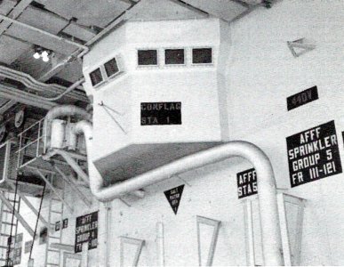
Conflagration Station # 1 was the master control station Conflag #2-4 were smaller. The bulkhead markings show the locations of equipment. There is an AFFF sprinkler group control as well as a AFFF and salt water fire hoses. The 440V sign indicates an aircraft power station. Note the incandescent lighting.
There were 3 fuel and defuel stations around the hanger. There were two sliding padeyes for use during UNREPs and fuel transfer hoses were hung on the bulkheads as well. There were a number of overhead cranes, two for AIMD Power Plants (one inside and one outside), one for the Mezzanine, one for the Calibration Lab and one for the ECM Vans. There were 4 large rectangular hatches in the hanger deck the most forward was a weapons elevator the other in the forward hanger was a shaft for stowing stores I believe. These two both were hinged on the long edge. In the aft hanger there were two more which lifted out on tracks exposing vertical shafts for stores. There were a number of oval hatches which I never learned the purpose of.
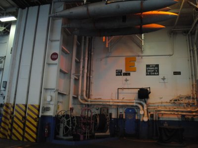
Good shot of the midships fuel station from the last deployment 2012. This is pretty much the same layout for this area in 1978 the color scheme is different but most things are in the same places.
We spent a good deal of our maintenance time on aircraft struck below. Any downing gripe that couldn’t be worked off easily usually went to the hanger. All the big aircraft inspections were performed there. Aircraft that needed to be jacked up for inspections or landing gear issues would be given space on the centerline. Engine changes, weapons station changes and M61A1 gun changes were done below. A huge amount of labor was devoted to corrosion control. We still painted entire aircraft at that time but this could not be done on the ship. The fumes were too dangerous in such confined quarters. Aboard we were limited to touch up only to cover bare metal but aircraft could be left ashore for painting at NAS Cubi Point, RP which had a dedicated corrosion control hanger.
While we worked up it was common to have white lights in the hanger but we also practiced for Darken Ship. On the Enterprise during this time frame they used incandescent flood lights. After we deployed outside of U.S. waters the ship would set Darken Ship nightly and only red lights were used in the hanger at night. On the flight deck all the lights were off. I particularly hated trying to do corrosion control under red lighting. Most of the work had to be done at night under red lights and the quality assurance inspections would be done in the daytime. They always found something we missed and that would get you in hot water with the Shop Supervisor and/or the Maintenance Chief, “Why can’t you **%#! guys get it right the first time?” During the daylight hours it was all about the flight schedule.
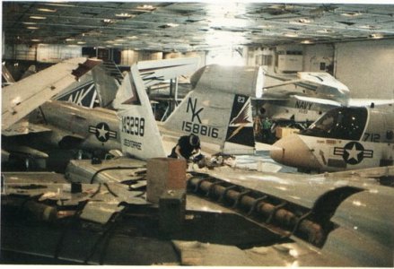
This is the hanger during my 1976 deployment.
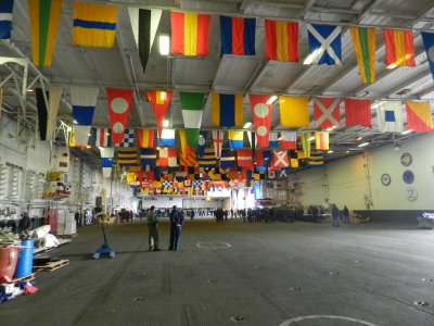
This is the hanger probably in the ships home port sometime in the 2000's. No aircraft are present and it appears that they are prepping for some ceremony or event. In the bow they have expanded the overhang some more to add a fitness center which helps date the photo.
In the Navy, or any branch of the military, a good portion of your time requires standing in line. You will stand in line to see a doctor, go to the dentist, get a haircut, shop in the ship’s store, get your paycheck, cash your paycheck, get vaccinated, sometimes even to use a toilet or take a shower, go to personnel or disbursing ( The pay guys), buy stamps or other post office stuff, go on liberty and eat. There are probably other things you had to stand in line for but those are the primary reasons. After a tour of duty you could say to a new guy I have more time standing in line than you have in the Navy and be quite accurate
The last two reasons for being in a line often required starting far from your goal and formed up or ended in the hanger deck. On the Enterprise there were two galleys with two lines for each on the 2nd deck. There was some overlap but they weren’t necessarily all open at the same time. The forward galley was the Navy version of fast food. It served soups, salads, sandwiches and for breakfast, scrambled eggs bacon, sausage, toast and cereal. Generally you could co to the forward galley and get in, eat and be out in 30 minutes or so. Only rarely did the line have to go up to the hanger bay. If you wanted a full on sit down meal then you needed to go to the aft galley. Unfortunately 3 thousand other people usually had the same idea at the same time as you.
The line started just aft of each serving line and before it wandered into the first berthing compartment aft it went up a ladder and into the hanger. If the galley was serving something popular it might stretch from that ladder to the divisional doors. Waiting in line 30 minutes to an hour was entirely possible. If you were on shift more often than not you’d just eat in the forward galley so you could get back to the shop so someone else could go to chow. I would eat in the aft galley before or after my shift for breakfast because the lines were down by then and they cooked omelets and eggs to order (breakfast for supper). If they were serving something particularly good I’d get up a little early and have supper (for breakfast).
Now the other reason to be standing in a line in the hanger was for liberty, beautiful liberty in exotic foreign ports. It was a chance to get out in the world and off the ship. When we anchored in the harbor for Hobart Tasmania in 1976 or Perth Australia in 1978 the liberty line went by paygrade and went on forever. They would call away rank by rank and then you could go get in line. It would stretch through the entire hanger. For a port like Karachi Pakistan where we were told not to eat or drink anything in town then the line wasn’t so long. The ship had to set up a barbecue and drink station on the landing in Karachi. The aft accommodation ladder on the fantail via AIMD Power Plants shop was the only way off the ship in most ports and you had to wait for ferries or liberty boats to arrive and start loading. In Hobart we stood in line for nearly 2 hours to go ashore on the first day and we waited for the lines to go down. After the first days liberty party had gone ashore the lines were only about an hour.
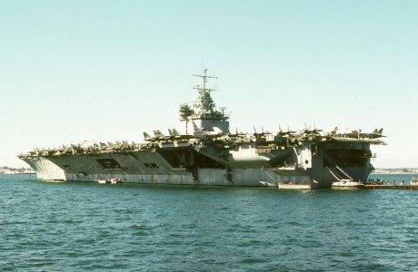
USS Enterprise (CVN 65) anchored off Fremantle, Western Australia in August 1978. The round opening on the hull over the aft sponson is the jet engine test cell.
I have participated in multiple working parties in the hanger including the Scrubbex mentioned previously. During UNREP/VERTREP all those stores coming aboard needed to be stowed away fast and the air wing troops were only good for one thing and that was to act as strong backs moving stuff below. I have worked far below stowing food into the freezers and store rooms, up on the Mezzanine pushing barrels onto pallets and down in the hanger moving boxes along on those conveyers with the rollers. When ammo came aboard that was mainly the Weapons Departments bailiwick.
If you were lollygagging about (goofing off) or working on an aircraft when a FOD walk down was called away then you were automatically part of that, same thing on the flight deck for that matter. Any GQ evolutions would catch you up in the drill if you were in the hanger when it was called away. Being up in the shop was no guarantee of staying out of any of those evolutions because the shop supervisor could order you into it or the Maintenance Chief could call the shop seeking more “volunteers.”
Now on to building a hanger deck in miniature; I have spent more time thinking, researching, planning and drawing this part of the build than it actually took me to construct it. Years ago when I was building the hanger for the 1/400 scale Enterprise, I made the basic parts quite easily but I found that the details were making me go around in circles. I would make the parts for say the shops in the aft end of the hanger and go through 2 or 3 iterations of that set and then maddeningly find some new photograph that had me doing it over again. Tired of reworking the thing over and over, I decided to first collect as many photographs as I could find and then draw a set of plans to lock down what I would build.
First I drew the elevations or the bulkheads for the starboard side, port side, forward, aft and divisional doors. I poured over the photos and painstakingly compiled a picture of the final product. This steamrolled however because after I completed the bulkheads I decided I needed a plan view which became plan views of the 1st deck, 01 level, 02 level and even some of the 03 level. Of course I should include the sponsons and…. then it became a never ending monster. I spent something on the order of 4 years making drawings from 2012 to 2016. I did these drawings in a bitmap raster program called Photo Impact which is similar to Adobe Photoshop or Corel Photo Paint. These drawings were originally made for the AMR 1/400 scale Enterprise but are up-scaled to 1/350. There is a 6 inch ruler on each drawing to help you get the size right.
I tried downloading some of the drawings below myself to make sure it worked and it appears it does not. If you want to get decent files go to the end of the fourth part of this post and there is a link to some better quality files.

Plate 02A Starboard Hanger Bay Elevations

Plate 02B Port Hanger Bay Elevations

Plate 02C Fore and Aft Elevations and Plan Details

Plate 03A Hanger Deck 1st Deck

Plate 03B Hanger Deck 01 Level

Plate 03C Hanger Deck 02 Level

Plate 03D Hanger Overhead
You may use these drawings for your own models, but keep in mind that unless you are building the A/M/R version they will only be useful as a reference.
When I went to the MHM 1/350 scale kit I thought I would just up-scale the drawings. Unfortunately the two models are not simply a different scale kit of the same thing. The locations of the various items are not the same. I needed a drawing of the hanger deck for this kit. I really did not want to start from scratch. On an IPMS website I found a review of a set of drawings for the Tamiya kit. The drawings were by a fellow modeler named Tom Pope. I put the link below again. His drawing will allow you to cut out most of the deck and drop it into place. He has copyrighted his drawing and there is a small charge for it.
https://reviews.ipmsusa.org/review/cvn-65-uss-enterprise-hangar-deck-scale-drawings
I took Tom’s drawings and added some details from my research. I made them the full length of the aft hull from the where the bow is glued on to the fantail. I marked out the locations of the bulkheads. I added the deck hatches and door tracks for the divisional doors and the hanger doors. I got ahold of Tom and obtained his permission to post those drawings for these parts in this post and you may use them for your models.

Hanger Template

Hanger Overhead Light Template. The lights here were moved around to better fit my model so you may find that you will need to adjustments.
I wanted to make the hanger deck from a single sheet of plastic. I started looking for a large sheet of .040” or better yet .060” sheet. I did not find anything in the hobby shops in my area at the time. They couldn’t or wouldn’t even special order it in that size. I went to the internet. I checked the sites for Evergreen and Plastruct plastics. Low and behold I was able to obtain from Plastruct 36” x 12” X .060” and .040”sheets. To be safe I got 2 of each of them. I stored these flat on a shelf in my garage for several years until I was ready to cut plastic. They are still available in their catalog. Simply go to Plastruct.com open the catalog and find what you need. There is a page for plain white styrene sheet in various sizes. They sell a mountain of architectural parts as well as strip and sheet. They do have a minimum order of $20.00 U.S. before they will ship it to you.
The full sheet from Plastruct.
To add the hanger deck you first have to make some way to support it. I took some fairly heavy Evergreen strip, .060” X .250” and began gluing it to the inside hull below the starboard hanger doors. To make sure that it was the right height I took a small piece of .060” X .060” strip and laid it on top adjusting the height until the small strip was just flush with the door opening. While the first section was drying I measured from the heavy strip to the hull bottom at the doors. I used this measurement to adjust the strips where there wasn’t any visual reference. This is made easy in the MHM kit as the upper hull is cut off at the waterline which gives it a constant depth.
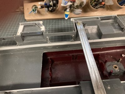
Here I have started the framework for the hanger deck.
To make cross beams I measured with a pair of dividers and glued sections of the heavy strip under the longitudinal stringer on the hull. Then I glued another piece vertically on top of the horizontal beam. This formed a T beam and proved to be very strong. You want to be accurate as possible here because if the beam is too wide you will distort the hull. Wherever possible I added a vertical support under the beam in the center of the hull. There is one where the motor and transmission will be installed that does not have a vertical strut but this doesn’t seem to be a problem. I used solvent glues on this part of the job because I wanted the parts to be welded together. Later when I had to make the hanger deck from .040” sheet instead of the .060” I added a cap of .020” X .060” strip to the top of the entire framework structure.
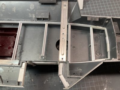
The bow.
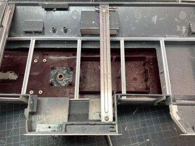
Midships.
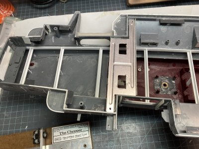
The stern. I have laid the kit fantail in place to see if the frame will work with my deck.
The Silhouette machine was made for scrap bookers and other home crafters and was designed to cut paper, cardboard, vinyl and things like that. I saw a video review of the thing on a modeling website cutting plastic sheet. I was hooked. I asked for it for Christmas that year. It is very handy and I confess that I use it a lot. It simply cuts straighter and more accurately than I ever could. But like all technology there is a learning curve. I made a new drawing based on Tom’s hanger and printed it out as a banner before I made the plastic version. I cut the diagram out and set it onto my hanger support structure. It dropped right into position. But the drawing indicated where some corrections were needed and these were made, printed and confirmed. This base drawing was used to build up the program for cutting and engraving the hanger deck in the Silhouette Design Studio proprietary software. When I did the hanger for the AMR Enterprise it was several days of cut, sand and try it then repeat trial and error.
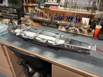
Here I have printed, cut out and laid my drawing on the frame to see how it will fit.
The material you want to cut is placed on a self-adhesive cutting mat. You then load the material and the mat into the machine and adjust the cutting settings and off it goes. The mats are designed to track through the machine with great accuracy. I did find that it was better to use slower speeds, smaller cutting depths, which were increased gradually for deep cuts, cutting complex drawings in several smaller jobs and making multiple passes. Now for this to work you don’t want the material to move on the mat. Even with a new mat the plastic sheet tended to move on the mat in tiny increments. This would ruin a cut project immediately since the mat is the reference point. My solution was to tape the work down on the mat. Do not rely on just the adhesive on the mat. But do not place tape where the machines primary rollers will go directly over it. I found that this would cause the knife to lock up. The silhouette mats are very sticky and might have worked but I found less expensive mats on Amazon so…
The literature I received said you could load larger projects directly into the machine with no mat. It might be okay to do this with paper or card stock but it did not work with the large plastic sheets. They slipped easily. The Silhouette folks make a 12” X 12” and a 12” X 24” mat but nothing longer. I took a 12” and a 24“ mat put them end to end and taped them together then placed my plastic sheet on it, taped everything down and still had problems until I cut a .040” sheet in half lengthwise. I just about had the .060” sheet working but ran out of unmarked blanks. When I ran the .040” material into the machine it finally worked beyond all my expectations. It took about 4 hours cutting slowly and multiple times. It did not shift on the mat nor did my homemade 36 inch mat shift in the machine. Full plastic sheets were just too heavy. There isn’t a setting for a 36” mat so you have to use the no mat settings.
I will have to end this post and continue in a second.
In this part I document my build-up of the hanger deck. I had to make 4 separate posts to accommodate all the photos and additional information.

This appears to be some sort of time lapse of the hanger note the group of people to the right which are faded out. It was taken in front of the Power Plants shop facing forward. All the elevator doors are closed. The forward end is in its original configuration before the addition of the overhanging shops. All the way forward the roll-up doors to the left are the GSE shops. Just off the centerline is the entrance to the tunnel and the forward weapons elevator trunk is to the right. You are looking through the divisional doors at the backside of the bulkheads that cover them. The aft weapons elevators are to the right just forward of elevator door # 3 on the right. Elevator door # 4 is on the left.
The hanger bay of the Enterprise was a cavernous area divided into two sections. It was 25’ high X 96’ wide (at the widest point) X 732’ long (.85” X 3.3” X 25.1” in 1/350 Scale). It began at frame 62, the divisional doors were at frame 153 and it ended at frame 242. It could house at least 1/3rd of the air wing or about 32 aircraft for CVW-14. At sea, deployed it was a noisy, chaotic scene of maintenance activity 24/7 for the entire deployment unless we were in a liberty port. Then a handful of aircraft were cleaned up and placed in the hanger as a display and all the others were crammed onto the flight deck. They did this in ports where visitors were permitted aboard to allow foot traffic with minimum peril from tie down chains and sharp surfaces. Usually they all went to the bow and guests were discouraged from walking around them.

View of the hanger in the late 60’s or early 70’s. Note how the aircraft are stacked in here and there is very little space remaining.
This movement was usually preceded by a flight deck and hanger deck scrub down of epic proportions. Zamboni scrubbers were not in use at the time so it was all done by massive working parties. Each division provided bodies. We manned salt water fire hoses and stiff bristled brooms. First we cleaned the stern then all the aircraft would be moved aft and we scrubbed the forward flight deck. At the same time the hanger would be undergoing the same treatment. If the port was important signal flags would be hung from the overhead.

Hanger deck Scrubbex in progress. This is from the 80’s but apparently they didn’t have a Zamboni yet.
The hanger housed a large inventory of GSE (Ground Support Equipment), numerous spare engines in cans, large parts for the catapults and arresting gear, any other material that couldn’t be stored somewhere else and the ships liberty boats Including the Captain’s Gig and the Admiral’s Barge. Even the overhead was used for storage with aircraft drop tanks located in racks. After the rework following this deployment racks were added for arresting gear cables in crates in the door well openings. During my time they were hung on the bulkheads wrapped in plastic. In a holdover from the Vietnam War the bulkheads were festooned with hooks which could take MER/TER bomb racks and launchers that the squadrons or weapons couldn’t store. These were now turned over to Weapons Department at the beginning of a deployment and kept in their spaces and the hooks were used for other things.

This is the GSE area in the early 80’s after the rework that changed the island. On the overhang at the 02 level the vans are not installed. The openings are the forward entrance to the vans.
Although I never saw a movie on the hanger deck of the Enterprise there was a projection booth on the port side of the hanger. KENT TV the Enterprise’s CC station played several movies each day and they could be viewed on any television connected to the system. Basketball hoops could be swung down for sporting events. They had a boxing ring that could be set up for smokers. There was a stage that could be set up for USO shows which usually occurred at least once during a deployment. Any free space was used by joggers, guys jumping rope, martial arts and there was even a group of cyclists who would set up their bicycles on stands and ride in place. The hanger was used for formations for various divisional/departmental quarters, award ceremonies or inspections. The MARDET (Marine Detachment) used the hanger for PT, close order drill and weapons inspection.

In this photo from one of the cruisebooks a basketball game is underway and to the right is the projection booth. This prior to the painting of the hanger deck murals.
The hanger had a great deal of installed firefighting equipment, salt water fire hose stations, AFFF hoses (Aqueous Film Forming Foam,) these were the older flaked hoses not the reels which would be installed after the 1978 deployment, spare hoses, hose extension wands, battle lanterns, sprinkler control groups, CO2 and PKP fire extinguishers, litters and first aid boxes. Looking over it all were the 4 Conflagration Stations high up on the bulkheads 2 per Hanger Bay. There were several lockers for damage control teams, life jacket lockers in case of abandon ship and a lot of large shoring timbers were stored on the bulkhead.

Conflagration Station # 1 was the master control station Conflag #2-4 were smaller. The bulkhead markings show the locations of equipment. There is an AFFF sprinkler group control as well as a AFFF and salt water fire hoses. The 440V sign indicates an aircraft power station. Note the incandescent lighting.
There were 3 fuel and defuel stations around the hanger. There were two sliding padeyes for use during UNREPs and fuel transfer hoses were hung on the bulkheads as well. There were a number of overhead cranes, two for AIMD Power Plants (one inside and one outside), one for the Mezzanine, one for the Calibration Lab and one for the ECM Vans. There were 4 large rectangular hatches in the hanger deck the most forward was a weapons elevator the other in the forward hanger was a shaft for stowing stores I believe. These two both were hinged on the long edge. In the aft hanger there were two more which lifted out on tracks exposing vertical shafts for stores. There were a number of oval hatches which I never learned the purpose of.

Good shot of the midships fuel station from the last deployment 2012. This is pretty much the same layout for this area in 1978 the color scheme is different but most things are in the same places.
We spent a good deal of our maintenance time on aircraft struck below. Any downing gripe that couldn’t be worked off easily usually went to the hanger. All the big aircraft inspections were performed there. Aircraft that needed to be jacked up for inspections or landing gear issues would be given space on the centerline. Engine changes, weapons station changes and M61A1 gun changes were done below. A huge amount of labor was devoted to corrosion control. We still painted entire aircraft at that time but this could not be done on the ship. The fumes were too dangerous in such confined quarters. Aboard we were limited to touch up only to cover bare metal but aircraft could be left ashore for painting at NAS Cubi Point, RP which had a dedicated corrosion control hanger.
While we worked up it was common to have white lights in the hanger but we also practiced for Darken Ship. On the Enterprise during this time frame they used incandescent flood lights. After we deployed outside of U.S. waters the ship would set Darken Ship nightly and only red lights were used in the hanger at night. On the flight deck all the lights were off. I particularly hated trying to do corrosion control under red lighting. Most of the work had to be done at night under red lights and the quality assurance inspections would be done in the daytime. They always found something we missed and that would get you in hot water with the Shop Supervisor and/or the Maintenance Chief, “Why can’t you **%#! guys get it right the first time?” During the daylight hours it was all about the flight schedule.

This is the hanger during my 1976 deployment.

This is the hanger probably in the ships home port sometime in the 2000's. No aircraft are present and it appears that they are prepping for some ceremony or event. In the bow they have expanded the overhang some more to add a fitness center which helps date the photo.
In the Navy, or any branch of the military, a good portion of your time requires standing in line. You will stand in line to see a doctor, go to the dentist, get a haircut, shop in the ship’s store, get your paycheck, cash your paycheck, get vaccinated, sometimes even to use a toilet or take a shower, go to personnel or disbursing ( The pay guys), buy stamps or other post office stuff, go on liberty and eat. There are probably other things you had to stand in line for but those are the primary reasons. After a tour of duty you could say to a new guy I have more time standing in line than you have in the Navy and be quite accurate
The last two reasons for being in a line often required starting far from your goal and formed up or ended in the hanger deck. On the Enterprise there were two galleys with two lines for each on the 2nd deck. There was some overlap but they weren’t necessarily all open at the same time. The forward galley was the Navy version of fast food. It served soups, salads, sandwiches and for breakfast, scrambled eggs bacon, sausage, toast and cereal. Generally you could co to the forward galley and get in, eat and be out in 30 minutes or so. Only rarely did the line have to go up to the hanger bay. If you wanted a full on sit down meal then you needed to go to the aft galley. Unfortunately 3 thousand other people usually had the same idea at the same time as you.
The line started just aft of each serving line and before it wandered into the first berthing compartment aft it went up a ladder and into the hanger. If the galley was serving something popular it might stretch from that ladder to the divisional doors. Waiting in line 30 minutes to an hour was entirely possible. If you were on shift more often than not you’d just eat in the forward galley so you could get back to the shop so someone else could go to chow. I would eat in the aft galley before or after my shift for breakfast because the lines were down by then and they cooked omelets and eggs to order (breakfast for supper). If they were serving something particularly good I’d get up a little early and have supper (for breakfast).
Now the other reason to be standing in a line in the hanger was for liberty, beautiful liberty in exotic foreign ports. It was a chance to get out in the world and off the ship. When we anchored in the harbor for Hobart Tasmania in 1976 or Perth Australia in 1978 the liberty line went by paygrade and went on forever. They would call away rank by rank and then you could go get in line. It would stretch through the entire hanger. For a port like Karachi Pakistan where we were told not to eat or drink anything in town then the line wasn’t so long. The ship had to set up a barbecue and drink station on the landing in Karachi. The aft accommodation ladder on the fantail via AIMD Power Plants shop was the only way off the ship in most ports and you had to wait for ferries or liberty boats to arrive and start loading. In Hobart we stood in line for nearly 2 hours to go ashore on the first day and we waited for the lines to go down. After the first days liberty party had gone ashore the lines were only about an hour.

USS Enterprise (CVN 65) anchored off Fremantle, Western Australia in August 1978. The round opening on the hull over the aft sponson is the jet engine test cell.
I have participated in multiple working parties in the hanger including the Scrubbex mentioned previously. During UNREP/VERTREP all those stores coming aboard needed to be stowed away fast and the air wing troops were only good for one thing and that was to act as strong backs moving stuff below. I have worked far below stowing food into the freezers and store rooms, up on the Mezzanine pushing barrels onto pallets and down in the hanger moving boxes along on those conveyers with the rollers. When ammo came aboard that was mainly the Weapons Departments bailiwick.
If you were lollygagging about (goofing off) or working on an aircraft when a FOD walk down was called away then you were automatically part of that, same thing on the flight deck for that matter. Any GQ evolutions would catch you up in the drill if you were in the hanger when it was called away. Being up in the shop was no guarantee of staying out of any of those evolutions because the shop supervisor could order you into it or the Maintenance Chief could call the shop seeking more “volunteers.”
Now on to building a hanger deck in miniature; I have spent more time thinking, researching, planning and drawing this part of the build than it actually took me to construct it. Years ago when I was building the hanger for the 1/400 scale Enterprise, I made the basic parts quite easily but I found that the details were making me go around in circles. I would make the parts for say the shops in the aft end of the hanger and go through 2 or 3 iterations of that set and then maddeningly find some new photograph that had me doing it over again. Tired of reworking the thing over and over, I decided to first collect as many photographs as I could find and then draw a set of plans to lock down what I would build.
First I drew the elevations or the bulkheads for the starboard side, port side, forward, aft and divisional doors. I poured over the photos and painstakingly compiled a picture of the final product. This steamrolled however because after I completed the bulkheads I decided I needed a plan view which became plan views of the 1st deck, 01 level, 02 level and even some of the 03 level. Of course I should include the sponsons and…. then it became a never ending monster. I spent something on the order of 4 years making drawings from 2012 to 2016. I did these drawings in a bitmap raster program called Photo Impact which is similar to Adobe Photoshop or Corel Photo Paint. These drawings were originally made for the AMR 1/400 scale Enterprise but are up-scaled to 1/350. There is a 6 inch ruler on each drawing to help you get the size right.
I tried downloading some of the drawings below myself to make sure it worked and it appears it does not. If you want to get decent files go to the end of the fourth part of this post and there is a link to some better quality files.

Plate 02A Starboard Hanger Bay Elevations

Plate 02B Port Hanger Bay Elevations

Plate 02C Fore and Aft Elevations and Plan Details

Plate 03A Hanger Deck 1st Deck

Plate 03B Hanger Deck 01 Level

Plate 03C Hanger Deck 02 Level

Plate 03D Hanger Overhead
You may use these drawings for your own models, but keep in mind that unless you are building the A/M/R version they will only be useful as a reference.
When I went to the MHM 1/350 scale kit I thought I would just up-scale the drawings. Unfortunately the two models are not simply a different scale kit of the same thing. The locations of the various items are not the same. I needed a drawing of the hanger deck for this kit. I really did not want to start from scratch. On an IPMS website I found a review of a set of drawings for the Tamiya kit. The drawings were by a fellow modeler named Tom Pope. I put the link below again. His drawing will allow you to cut out most of the deck and drop it into place. He has copyrighted his drawing and there is a small charge for it.
https://reviews.ipmsusa.org/review/cvn-65-uss-enterprise-hangar-deck-scale-drawings
I took Tom’s drawings and added some details from my research. I made them the full length of the aft hull from the where the bow is glued on to the fantail. I marked out the locations of the bulkheads. I added the deck hatches and door tracks for the divisional doors and the hanger doors. I got ahold of Tom and obtained his permission to post those drawings for these parts in this post and you may use them for your models.

Hanger Template

Hanger Overhead Light Template. The lights here were moved around to better fit my model so you may find that you will need to adjustments.
I wanted to make the hanger deck from a single sheet of plastic. I started looking for a large sheet of .040” or better yet .060” sheet. I did not find anything in the hobby shops in my area at the time. They couldn’t or wouldn’t even special order it in that size. I went to the internet. I checked the sites for Evergreen and Plastruct plastics. Low and behold I was able to obtain from Plastruct 36” x 12” X .060” and .040”sheets. To be safe I got 2 of each of them. I stored these flat on a shelf in my garage for several years until I was ready to cut plastic. They are still available in their catalog. Simply go to Plastruct.com open the catalog and find what you need. There is a page for plain white styrene sheet in various sizes. They sell a mountain of architectural parts as well as strip and sheet. They do have a minimum order of $20.00 U.S. before they will ship it to you.

The full sheet from Plastruct.
To add the hanger deck you first have to make some way to support it. I took some fairly heavy Evergreen strip, .060” X .250” and began gluing it to the inside hull below the starboard hanger doors. To make sure that it was the right height I took a small piece of .060” X .060” strip and laid it on top adjusting the height until the small strip was just flush with the door opening. While the first section was drying I measured from the heavy strip to the hull bottom at the doors. I used this measurement to adjust the strips where there wasn’t any visual reference. This is made easy in the MHM kit as the upper hull is cut off at the waterline which gives it a constant depth.

Here I have started the framework for the hanger deck.
To make cross beams I measured with a pair of dividers and glued sections of the heavy strip under the longitudinal stringer on the hull. Then I glued another piece vertically on top of the horizontal beam. This formed a T beam and proved to be very strong. You want to be accurate as possible here because if the beam is too wide you will distort the hull. Wherever possible I added a vertical support under the beam in the center of the hull. There is one where the motor and transmission will be installed that does not have a vertical strut but this doesn’t seem to be a problem. I used solvent glues on this part of the job because I wanted the parts to be welded together. Later when I had to make the hanger deck from .040” sheet instead of the .060” I added a cap of .020” X .060” strip to the top of the entire framework structure.

The bow.

Midships.

The stern. I have laid the kit fantail in place to see if the frame will work with my deck.
The Silhouette machine was made for scrap bookers and other home crafters and was designed to cut paper, cardboard, vinyl and things like that. I saw a video review of the thing on a modeling website cutting plastic sheet. I was hooked. I asked for it for Christmas that year. It is very handy and I confess that I use it a lot. It simply cuts straighter and more accurately than I ever could. But like all technology there is a learning curve. I made a new drawing based on Tom’s hanger and printed it out as a banner before I made the plastic version. I cut the diagram out and set it onto my hanger support structure. It dropped right into position. But the drawing indicated where some corrections were needed and these were made, printed and confirmed. This base drawing was used to build up the program for cutting and engraving the hanger deck in the Silhouette Design Studio proprietary software. When I did the hanger for the AMR Enterprise it was several days of cut, sand and try it then repeat trial and error.

Here I have printed, cut out and laid my drawing on the frame to see how it will fit.
The material you want to cut is placed on a self-adhesive cutting mat. You then load the material and the mat into the machine and adjust the cutting settings and off it goes. The mats are designed to track through the machine with great accuracy. I did find that it was better to use slower speeds, smaller cutting depths, which were increased gradually for deep cuts, cutting complex drawings in several smaller jobs and making multiple passes. Now for this to work you don’t want the material to move on the mat. Even with a new mat the plastic sheet tended to move on the mat in tiny increments. This would ruin a cut project immediately since the mat is the reference point. My solution was to tape the work down on the mat. Do not rely on just the adhesive on the mat. But do not place tape where the machines primary rollers will go directly over it. I found that this would cause the knife to lock up. The silhouette mats are very sticky and might have worked but I found less expensive mats on Amazon so…
The literature I received said you could load larger projects directly into the machine with no mat. It might be okay to do this with paper or card stock but it did not work with the large plastic sheets. They slipped easily. The Silhouette folks make a 12” X 12” and a 12” X 24” mat but nothing longer. I took a 12” and a 24“ mat put them end to end and taped them together then placed my plastic sheet on it, taped everything down and still had problems until I cut a .040” sheet in half lengthwise. I just about had the .060” sheet working but ran out of unmarked blanks. When I ran the .040” material into the machine it finally worked beyond all my expectations. It took about 4 hours cutting slowly and multiple times. It did not shift on the mat nor did my homemade 36 inch mat shift in the machine. Full plastic sheets were just too heavy. There isn’t a setting for a 36” mat so you have to use the no mat settings.
I will have to end this post and continue in a second.
Last edited:
- Joined
- May 8, 2021
- Messages
- 53
- Points
- 78

This is the second post of my Enterprise Hanger construction.
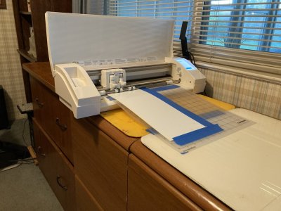
This how I arranged the machine during the engraving and cutting of the hanger deck.
I tried to draw several versions of padeyes for the machine to engrave but none of them worked well so I settled for a small index mark at each padeye location. I used the same tool that I made for the flight deck to represent padeyes in the hanger. I used the same spacing for the padeyes as on the flight deck.
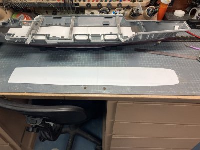
The newly cut hanger deck sitting beside the model.
In each elevator well there is a railing that raises and lowers depending on the position of the elevator. When the elevator is up at the flight deck the safety rails are raised in the hanger. Or if the elevator is down then the barrier is up on the flight deck. I set up an engraving for this too because the real thing is recessed in the deck. I will need to manually scribe them on the flight deck as well. The door tracks have a series of rectangular metal plates that move with the doors as they travel. They cover the actual track to keep out debris. Finally inboard of the hanger door tracks is a grate over a scupper or drain for sea water. I probably could have gotten the machine to engrave something for this but I just represented it with a thin rectangle. I had the machine cut these nearly all the way through. Later I punched them out and glued a .030” X .040” strip in the slot partially filling it. I cut some photoetched grating material and glued it in the remaining .010” space.
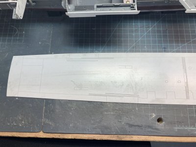
This is the aft section of the hanger I have wiped the surface with black water color to bring out the engravings.
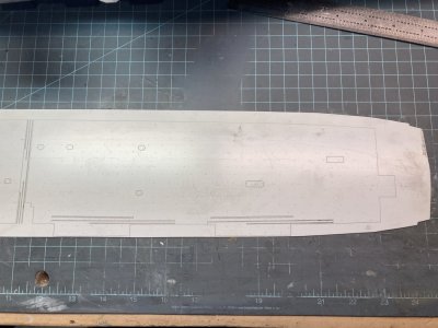 Hanger Deck (28)
The forward section it was too big to photograph up close in one shot.
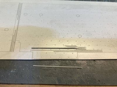
The scupper is punched out.
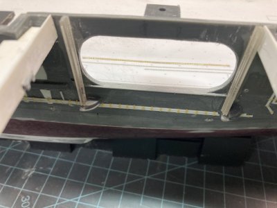 Hanger Deck (42)
The photoetched grate is installed to represent the scupper.
When I placed the plastic deck onto the supports it fit very well. I had to sand the bow and stern area edges at an angle to match the shape of the hull. There were some places with gaps but most of those would be hidden. Around Elevator 2 I added some strip to the edge to fill a gap. I also added some to the fantail and bow to get a tight fit. That was my fault for sanding a bit too enthusiastically. I was very pleased to get this all to work so well.
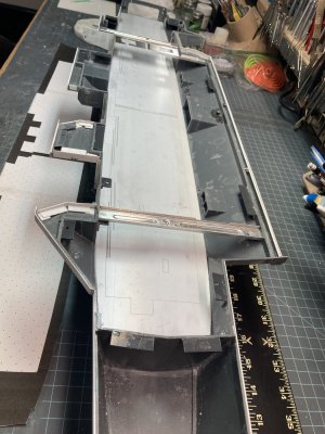
It fits!
The plastic of the models hull is very thick, .060” or more in places. The hanger door openings, the fantail opening and the various doors needed to be thinned down for a more scale appearance. I laid the hanger deck in place the glued sandpaper to thin wood shim stock. This can be held against the hull and you can sand the hull without marring the deck. I thinned the hull to approximately .040”. This step had to be complete before I started building up the bulkheads.
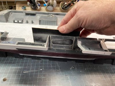
Sanding down the elevator door area.
I next set up a new cut job for the hanger bulkheads. The hanger door openings in particular are difficult to get consistent. I did not make every piece but made several lengths of the hangers overall height. I also wanted the double watertight doors at the stern, bow, Sponsons 1, 4 and 5 open. So they were also programmed into the cut job. The garage door openings at the bow and stern were also cut out. I used 2 .020” X 6“ X 12“ Evergreen plastic sheets to make it all. When I had all these parts ready I began assembling the bulkheads.
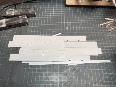 Hanger Deck (47)
The parts for the bulkheads.
I used the elevator door wells as my starting point. I glued the fore and aft bulkheads to the inner door well opening and used a square to keep them plum and true while the glue set. I then added a piece for the overhead. To help fix these into position dry I added a piece of 5/16” angle to the fore and aft ends. The door wells were taped in place and I drilled holes to receive 1/16” rod in the angle and through the deck. Short sections of rod were secured with tube glue fixing them to the angle only. After this had dried I removed the tape and glued a small piece of angle to the hull above the door opening. This holds the door well in position relatively securely.
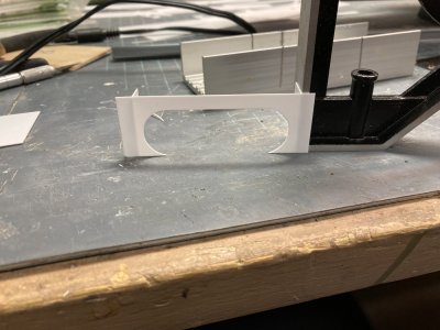
Building a Door well.
The very forward and aft bulkheads were next to position. I had engraved lines on the hanger deck to show me where to place all the bulkheads so the positioning was fairly easy. I used more of the large angle with pins to anchor them in place and used small angle to help hold them in place vertically. On the starboard side the bulkheads are typically smaller sections between the aft end and from door well to door well. I used the same techniques to hold them in position but also glued a piece of overlapping strip at each junction on the back of one of the bulkhead parts. This provides support for the sections of bulkhead and eventually a gluing surface. All of the parts were left unglued to the hanger deck in order to remove each part for detailing and painting.
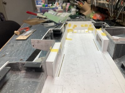
The tape up of the first hanger parts.
On the port side I tried to make a single piece from the Elevator 4 door well to the bow. I did get it all pinned down but the long piece kept bowing and lifting in the middle. I had some extra holes for pins by the time I was done and I had to fill these in with more rod which was cut flush when dry. To fix the bowing problem I cut a section out of the middle of the length and got it to set down properly. Then I made a section to fill the gap and glued the 3 pieces together. At the bow where they will be hidden I put opposing pieces of large angle to hold the port and starboard bulkheads vertically. With the four walls standing up and connected I moved on to making the divisional doors and then the ordnance elevator shafts on the starboard side.
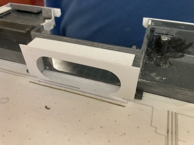
I have added the overhead and angle to position each door.
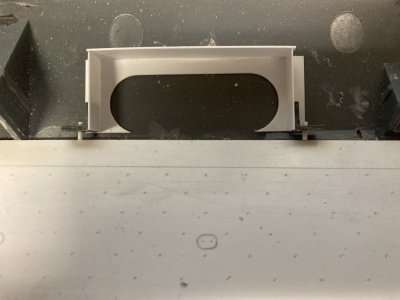
This how I will locate the parts each time.
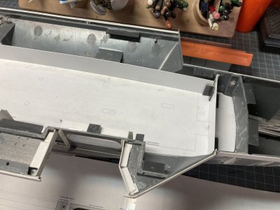
The port bulkhead you can see the joint at the forward bulkhead. The port side is sitting down fine now but when I drilled the angles through the deck I moved things just enough to cause problems.
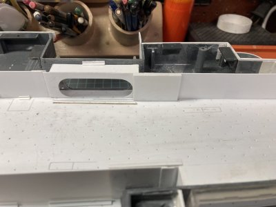
You can see how the elevator doors help with the joins in the bulkheads. In other place I have a short piece glued to one side to hold two sections together.
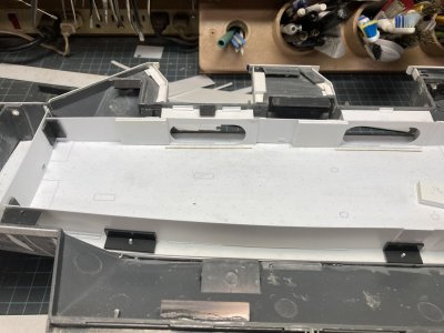
Most of the port and starboard bulkheads are now located with pins, above the door wells a small piece of angle holds them down better and I have cut and rejoined the port bulkhead.
For the divisional doors I used 3 sections of .060” sheet cut to the proper size from my plans, separated by .010” strip layered to give the doors the correct thickness to match the engraved tracks. I made a set for each side and allowed the glue to dry overnight. These are cut slightly shorter than the hanger doors to account for the overhead tracks. The next day I drilled each set of doors vertically at the middle door. When both sets were done I positioned them in the hanger and drilled through the deck. This allowed me to pin each set of doors in place. On the starboard side there is a structure on the forward end, on the aft a bulkhead with a flange on the inside edge.
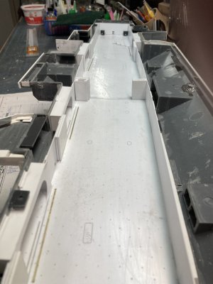
I am building up the divisional doors. The starboard side structure is in place but not the aft bulkheads.
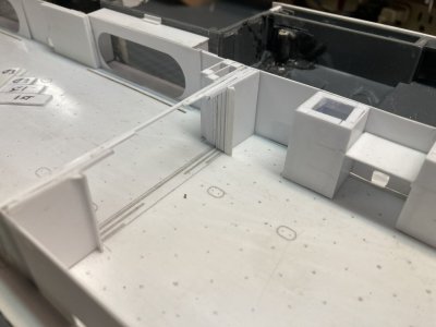
Here is the completed unit with the door tracks in place. Off to the right the basic weapons elevator shafts are glued to the bulkhead.
The Port side only has the aft bulkhead mirroring the port. I used .020” sheet to make these and separated them from the doors with .010” strip. The center set of doors has a keyed edge to fit snugly together when closed. I used .010“ X .020” strip on the edge of the doors to simulate this. On The port side a single strip centered vertically and on the starboard side 2 strips with a corresponding gap in the center. I used some very fine pieces of strip to fashion the upper door tracks. This was some finicky stuff but I finally got all the parts in place and aligned. The 4 sets of hanger doors were made the same way but they are the full height of the hanger. They were spaced with the .010” strip from the bulkhead. These were glued to the hanger bulkheads in the open positions. The upper tracks will be done later.
The two ordnance elevator shafts were made from .020” sheet backed up by thick strip. I first tried to pin these to the deck but went with gluing them to the bulkhead instead. Up until the yard period after the 1978 deployment there was a deck at the 02 level spanning them. There was a hoist that allowed large items to be brought up to the Calibration Lab as an option to the platform at Elevator 3. This was walled off sometime after that deployment but I am not sure when. Originally I thought these shafts had been rounded off on the vertical edges but a couple of good shots of the area finally came my way and dispelled that notion. The exteriors will require detailing with strip but during this initial part of the build will be just the basic construction. The doors to Sponson 7 lead to the After Brow or the enlisted access to the ship which was used in port tied to a pier.
When Enterprise was launched the forward bulkhead was a doorway to the tunnel area of avionics shops and supply work centers. The bulkhead at frame 62 is the doorway. There is an overhang over the door and a protrusion of the forward weapons elevator trunk on the starboard side of the entry way and GSE Shops on the port side. They extend out from frame 62 to frame 66. These features form the bulkhead of the forward hanger bay.
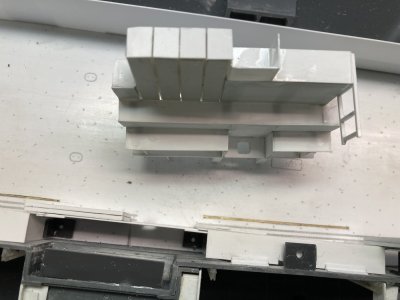
The completed basic forward bulkhead.
The forward overhangs were added because newer aircraft like the F-14A, A-7E, A6E, EA-6B and the E-2B had more complicated avionics which required additional shop space to repair it. The solution was the construction of the overhangs. I am not sure what was done but it occurred sometime between the after the 1969 cruise and before the 1974 deployment. On the starboard side the overhang could not connect up to the bulkhead because the open hanger doors were in the way. So the starboard side was supported by two pillars just inboard of the hanger doors. When I built my first version of the forward bulkhead it ended well forward of the open hanger doors which made the need for the pillars seem odd. You can’t see this area after everything is closed up but it really bugged me because I knew how it really looked.
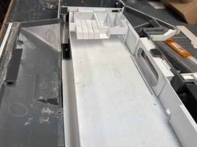
This the final position of the forward bulkhead adjusted to the kits door positions. Note how the structure is built around the elevator 1 doors.
The problem was the MHM and Tamiya kits elevator locations being off all along the starboard side. The forward elevator opening in the kit is at frame 89 but it should be at frame 82 by the Book of General Plans drawings. As a consequence when you build up the forward end of the hanger with its overhang it doesn’t end in the right place in relation to the open hanger doors. My engraved forward bulkhead line is right on frame 62. I needed to move the whole thing aft by 7 frames or about .5”. But if I moved it the front bulkhead wouldn’t be at frame 62 plus I would be losing some hanger space. I could have extended the overhang until it ended in the right spot but it would have looked too long that way. When I moved the entire assembly aft it looked more correct so that is what I went with positioning it at the engraved line for the GSE Shops vice the forward bulkhead.. The only way to really fix it would be to cut away the doors and move them. Then you would have to do the same thing with the elevator openings on the flight deck. It would be a very involved correction.
This overhang area was a very complicated structure featuring an inverted stair step design at the 01 and 02 levels. The 01 level is cantilevered over the structure on the main deck and it goes straight across. The 02 level is primarily the ECM shop that supports the EA-6B aircraft. It provides a location to connect the Vans. The 02 level is cantilevered over the 01 but it is not a straight line across. On the starboard side it is built around the open hanger doors. It juts out further than the port and there is an open platform on the starboard side which provides electrical and A/C connections to the vans. When the ship isn’t deployed and the vans have been removed the 02 level on the port side is a catwalk which would provide access to the forward end of the vans. AIMD (Aircraft Intermediate Maintenance Department) has hung various AIMD banners across this area.
This four 40’ ECM vans would be hung from the overhead prior to deployment. The trailers arrive like commercial shipping containers. The trailers are hoisted aboard and they are moved into position. The vans are raised up to the overhead and secured there and then the trailers are removed. On their aft end is another catwalk. These are part of each trailer. They form a feature of the forward hanger commonly called the balcony. There is a hoist operated from the catwalk to move equipment from the EA-6B ECM pods. The expense of equipping each carrier with these shops (WC 64C) full time was apparently just too much and the development of the vans was the solution. The vans are moved from ship to ship as they get close to movement overseas. When I was Ship’s company on the Kitty Hawk and Constellation the vans were not installed until the final work-up detachment before we deployed.
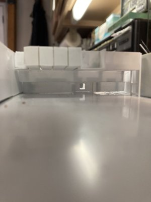
The ECM vans are the 4 boxes on the port side.
It is critical that you ensure your parts are squared up before gluing to ensure the overall look of the thing. I had purchased 1/350 scale 40’ trailers from Shapeways which turned out to be a little under scale. I had a full sheet of Evergreen .020” Railroad Car Siding which helped beef them out a bit. Most of the structure is .020” sheet backed up by square strip and angle. I worked on this subassembly for four 3 hour sessions before I finally got it to where it looks right. I had originally intended to have some of the roll up doors leading to the GSE shops open but because of the interior supports I shelved this idea for closed doors. My drawings helped me with the general shapes but couldn’t be used as plan drawings because of the differences in the models shapes.
I moved on to the shop area at the aft end of the hanger. The center section is AIMD Powerplants which has a large watertight double door out to the fantail which I have opened. This door is taller than standard doors to accommodate engines on trailers going out to the test cell. There are 4 roll up doors for Powerplants which will be open. To the port I believe was the Tire Shop and on the starboard side was Airframes. I am unsure of what was above the Powerplants Shop. Each of these has 1 Roll up door which will be closed. These shops were unique in that they were 1 ½ decks tall to starboard and 2 decks tall for the center and port. This was to accommodate the overhead crane system inside the Powerplants shop. Above Airframes was the Mezzanine which belonged to the supply department. To access it you had to go to the 02 level on the starboard side, through a door and down a short ladder. I got assigned to this area during a working party along with a friend who knew the way up to it or I would never have found it.
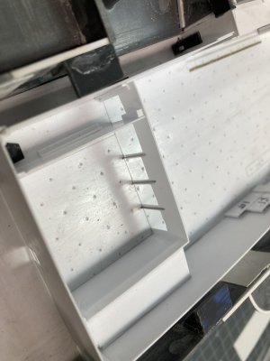 Hanger Deck (86)
The aft structure pinned in place.
The build-up of this area is much more straight forward than the bow construction. I already had the forward and aft bulkheads. I made 2 Side bulkheads both the height of the Powerplants Shop. I glued these to the forward bulkhead and reinforced the joints with strip and angle. I was a bit worried by the flimsiness of the area around the roll up doors though. I glued the door material on each of the outside shops to represent closed doors. I decided to pin each of the center 3 frame posts to the deck. I marked the locations from the front part. I used some stiff stainless safety wire to make pins which I superglued on the backside of the three center door frames. I marked their locations on the inside deck. I drilled each hole just inside the engraved line on the deck. This locates the shop parts solidly.
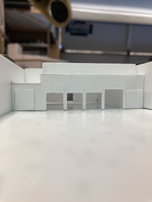
Looking through the completed basic aft structure to the fantail
I next fitted the deck for the Mezzanine and then the deck over Powerplants. With these glued in place and reinforced the aft shop area is pretty solid even if the aft bulkhead is not glued in place. I had to extend the port bulkhead at the Mezzanine up to the level of the aft bulkhead. Then I made a forward bulkhead for the top structure and reinforced them. With all of these parts constructed but not detailed the basic hanger bay is complete with the exception of the overhead.
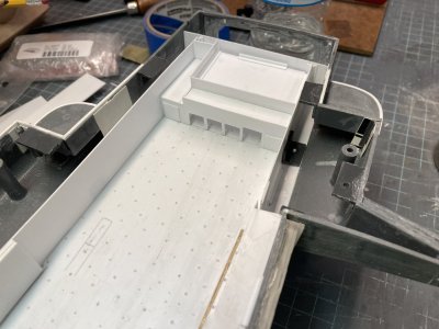
The aft structure. The Mezzanine is to the starboard side.
My hanger deck template provided the basic general shape for this part. I placed the printed hanger deck that I used to test the fit of the plastic hanger deck on top of the hanger structures. I made some penciled lines where the drawing will be changed for the overhead. I took this to my computer and made a new drawing for the overhead. I squared off the bow and extended the stern to fit correctly for the fantail overhead. I cut back both sides but left some material to overhang the bulkheads. On my model there are some plastic angle supports for the flight deck around the hull and I added cut outs to fit around them. This was printed and inserted over the hanger again. I found a few points that I wanted to adjust and took those corrections back to the computer.
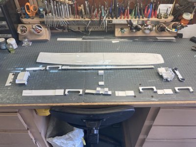
The various parts of the hanger laid out minus the overhead.
Well I have run out of picture room again so I will add a third post.

This how I arranged the machine during the engraving and cutting of the hanger deck.
I tried to draw several versions of padeyes for the machine to engrave but none of them worked well so I settled for a small index mark at each padeye location. I used the same tool that I made for the flight deck to represent padeyes in the hanger. I used the same spacing for the padeyes as on the flight deck.

The newly cut hanger deck sitting beside the model.
In each elevator well there is a railing that raises and lowers depending on the position of the elevator. When the elevator is up at the flight deck the safety rails are raised in the hanger. Or if the elevator is down then the barrier is up on the flight deck. I set up an engraving for this too because the real thing is recessed in the deck. I will need to manually scribe them on the flight deck as well. The door tracks have a series of rectangular metal plates that move with the doors as they travel. They cover the actual track to keep out debris. Finally inboard of the hanger door tracks is a grate over a scupper or drain for sea water. I probably could have gotten the machine to engrave something for this but I just represented it with a thin rectangle. I had the machine cut these nearly all the way through. Later I punched them out and glued a .030” X .040” strip in the slot partially filling it. I cut some photoetched grating material and glued it in the remaining .010” space.

This is the aft section of the hanger I have wiped the surface with black water color to bring out the engravings.
 Hanger Deck (28)
The forward section it was too big to photograph up close in one shot.

The scupper is punched out.
 Hanger Deck (42)
The photoetched grate is installed to represent the scupper.
When I placed the plastic deck onto the supports it fit very well. I had to sand the bow and stern area edges at an angle to match the shape of the hull. There were some places with gaps but most of those would be hidden. Around Elevator 2 I added some strip to the edge to fill a gap. I also added some to the fantail and bow to get a tight fit. That was my fault for sanding a bit too enthusiastically. I was very pleased to get this all to work so well.

It fits!
The plastic of the models hull is very thick, .060” or more in places. The hanger door openings, the fantail opening and the various doors needed to be thinned down for a more scale appearance. I laid the hanger deck in place the glued sandpaper to thin wood shim stock. This can be held against the hull and you can sand the hull without marring the deck. I thinned the hull to approximately .040”. This step had to be complete before I started building up the bulkheads.

Sanding down the elevator door area.
I next set up a new cut job for the hanger bulkheads. The hanger door openings in particular are difficult to get consistent. I did not make every piece but made several lengths of the hangers overall height. I also wanted the double watertight doors at the stern, bow, Sponsons 1, 4 and 5 open. So they were also programmed into the cut job. The garage door openings at the bow and stern were also cut out. I used 2 .020” X 6“ X 12“ Evergreen plastic sheets to make it all. When I had all these parts ready I began assembling the bulkheads.
 Hanger Deck (47)
The parts for the bulkheads.
I used the elevator door wells as my starting point. I glued the fore and aft bulkheads to the inner door well opening and used a square to keep them plum and true while the glue set. I then added a piece for the overhead. To help fix these into position dry I added a piece of 5/16” angle to the fore and aft ends. The door wells were taped in place and I drilled holes to receive 1/16” rod in the angle and through the deck. Short sections of rod were secured with tube glue fixing them to the angle only. After this had dried I removed the tape and glued a small piece of angle to the hull above the door opening. This holds the door well in position relatively securely.

Building a Door well.
The very forward and aft bulkheads were next to position. I had engraved lines on the hanger deck to show me where to place all the bulkheads so the positioning was fairly easy. I used more of the large angle with pins to anchor them in place and used small angle to help hold them in place vertically. On the starboard side the bulkheads are typically smaller sections between the aft end and from door well to door well. I used the same techniques to hold them in position but also glued a piece of overlapping strip at each junction on the back of one of the bulkhead parts. This provides support for the sections of bulkhead and eventually a gluing surface. All of the parts were left unglued to the hanger deck in order to remove each part for detailing and painting.

The tape up of the first hanger parts.
On the port side I tried to make a single piece from the Elevator 4 door well to the bow. I did get it all pinned down but the long piece kept bowing and lifting in the middle. I had some extra holes for pins by the time I was done and I had to fill these in with more rod which was cut flush when dry. To fix the bowing problem I cut a section out of the middle of the length and got it to set down properly. Then I made a section to fill the gap and glued the 3 pieces together. At the bow where they will be hidden I put opposing pieces of large angle to hold the port and starboard bulkheads vertically. With the four walls standing up and connected I moved on to making the divisional doors and then the ordnance elevator shafts on the starboard side.

I have added the overhead and angle to position each door.

This how I will locate the parts each time.

The port bulkhead you can see the joint at the forward bulkhead. The port side is sitting down fine now but when I drilled the angles through the deck I moved things just enough to cause problems.

You can see how the elevator doors help with the joins in the bulkheads. In other place I have a short piece glued to one side to hold two sections together.

Most of the port and starboard bulkheads are now located with pins, above the door wells a small piece of angle holds them down better and I have cut and rejoined the port bulkhead.
For the divisional doors I used 3 sections of .060” sheet cut to the proper size from my plans, separated by .010” strip layered to give the doors the correct thickness to match the engraved tracks. I made a set for each side and allowed the glue to dry overnight. These are cut slightly shorter than the hanger doors to account for the overhead tracks. The next day I drilled each set of doors vertically at the middle door. When both sets were done I positioned them in the hanger and drilled through the deck. This allowed me to pin each set of doors in place. On the starboard side there is a structure on the forward end, on the aft a bulkhead with a flange on the inside edge.

I am building up the divisional doors. The starboard side structure is in place but not the aft bulkheads.

Here is the completed unit with the door tracks in place. Off to the right the basic weapons elevator shafts are glued to the bulkhead.
The Port side only has the aft bulkhead mirroring the port. I used .020” sheet to make these and separated them from the doors with .010” strip. The center set of doors has a keyed edge to fit snugly together when closed. I used .010“ X .020” strip on the edge of the doors to simulate this. On The port side a single strip centered vertically and on the starboard side 2 strips with a corresponding gap in the center. I used some very fine pieces of strip to fashion the upper door tracks. This was some finicky stuff but I finally got all the parts in place and aligned. The 4 sets of hanger doors were made the same way but they are the full height of the hanger. They were spaced with the .010” strip from the bulkhead. These were glued to the hanger bulkheads in the open positions. The upper tracks will be done later.
The two ordnance elevator shafts were made from .020” sheet backed up by thick strip. I first tried to pin these to the deck but went with gluing them to the bulkhead instead. Up until the yard period after the 1978 deployment there was a deck at the 02 level spanning them. There was a hoist that allowed large items to be brought up to the Calibration Lab as an option to the platform at Elevator 3. This was walled off sometime after that deployment but I am not sure when. Originally I thought these shafts had been rounded off on the vertical edges but a couple of good shots of the area finally came my way and dispelled that notion. The exteriors will require detailing with strip but during this initial part of the build will be just the basic construction. The doors to Sponson 7 lead to the After Brow or the enlisted access to the ship which was used in port tied to a pier.
When Enterprise was launched the forward bulkhead was a doorway to the tunnel area of avionics shops and supply work centers. The bulkhead at frame 62 is the doorway. There is an overhang over the door and a protrusion of the forward weapons elevator trunk on the starboard side of the entry way and GSE Shops on the port side. They extend out from frame 62 to frame 66. These features form the bulkhead of the forward hanger bay.

The completed basic forward bulkhead.
The forward overhangs were added because newer aircraft like the F-14A, A-7E, A6E, EA-6B and the E-2B had more complicated avionics which required additional shop space to repair it. The solution was the construction of the overhangs. I am not sure what was done but it occurred sometime between the after the 1969 cruise and before the 1974 deployment. On the starboard side the overhang could not connect up to the bulkhead because the open hanger doors were in the way. So the starboard side was supported by two pillars just inboard of the hanger doors. When I built my first version of the forward bulkhead it ended well forward of the open hanger doors which made the need for the pillars seem odd. You can’t see this area after everything is closed up but it really bugged me because I knew how it really looked.

This the final position of the forward bulkhead adjusted to the kits door positions. Note how the structure is built around the elevator 1 doors.
The problem was the MHM and Tamiya kits elevator locations being off all along the starboard side. The forward elevator opening in the kit is at frame 89 but it should be at frame 82 by the Book of General Plans drawings. As a consequence when you build up the forward end of the hanger with its overhang it doesn’t end in the right place in relation to the open hanger doors. My engraved forward bulkhead line is right on frame 62. I needed to move the whole thing aft by 7 frames or about .5”. But if I moved it the front bulkhead wouldn’t be at frame 62 plus I would be losing some hanger space. I could have extended the overhang until it ended in the right spot but it would have looked too long that way. When I moved the entire assembly aft it looked more correct so that is what I went with positioning it at the engraved line for the GSE Shops vice the forward bulkhead.. The only way to really fix it would be to cut away the doors and move them. Then you would have to do the same thing with the elevator openings on the flight deck. It would be a very involved correction.
This overhang area was a very complicated structure featuring an inverted stair step design at the 01 and 02 levels. The 01 level is cantilevered over the structure on the main deck and it goes straight across. The 02 level is primarily the ECM shop that supports the EA-6B aircraft. It provides a location to connect the Vans. The 02 level is cantilevered over the 01 but it is not a straight line across. On the starboard side it is built around the open hanger doors. It juts out further than the port and there is an open platform on the starboard side which provides electrical and A/C connections to the vans. When the ship isn’t deployed and the vans have been removed the 02 level on the port side is a catwalk which would provide access to the forward end of the vans. AIMD (Aircraft Intermediate Maintenance Department) has hung various AIMD banners across this area.
This four 40’ ECM vans would be hung from the overhead prior to deployment. The trailers arrive like commercial shipping containers. The trailers are hoisted aboard and they are moved into position. The vans are raised up to the overhead and secured there and then the trailers are removed. On their aft end is another catwalk. These are part of each trailer. They form a feature of the forward hanger commonly called the balcony. There is a hoist operated from the catwalk to move equipment from the EA-6B ECM pods. The expense of equipping each carrier with these shops (WC 64C) full time was apparently just too much and the development of the vans was the solution. The vans are moved from ship to ship as they get close to movement overseas. When I was Ship’s company on the Kitty Hawk and Constellation the vans were not installed until the final work-up detachment before we deployed.

The ECM vans are the 4 boxes on the port side.
It is critical that you ensure your parts are squared up before gluing to ensure the overall look of the thing. I had purchased 1/350 scale 40’ trailers from Shapeways which turned out to be a little under scale. I had a full sheet of Evergreen .020” Railroad Car Siding which helped beef them out a bit. Most of the structure is .020” sheet backed up by square strip and angle. I worked on this subassembly for four 3 hour sessions before I finally got it to where it looks right. I had originally intended to have some of the roll up doors leading to the GSE shops open but because of the interior supports I shelved this idea for closed doors. My drawings helped me with the general shapes but couldn’t be used as plan drawings because of the differences in the models shapes.
I moved on to the shop area at the aft end of the hanger. The center section is AIMD Powerplants which has a large watertight double door out to the fantail which I have opened. This door is taller than standard doors to accommodate engines on trailers going out to the test cell. There are 4 roll up doors for Powerplants which will be open. To the port I believe was the Tire Shop and on the starboard side was Airframes. I am unsure of what was above the Powerplants Shop. Each of these has 1 Roll up door which will be closed. These shops were unique in that they were 1 ½ decks tall to starboard and 2 decks tall for the center and port. This was to accommodate the overhead crane system inside the Powerplants shop. Above Airframes was the Mezzanine which belonged to the supply department. To access it you had to go to the 02 level on the starboard side, through a door and down a short ladder. I got assigned to this area during a working party along with a friend who knew the way up to it or I would never have found it.
 Hanger Deck (86)
The aft structure pinned in place.
The build-up of this area is much more straight forward than the bow construction. I already had the forward and aft bulkheads. I made 2 Side bulkheads both the height of the Powerplants Shop. I glued these to the forward bulkhead and reinforced the joints with strip and angle. I was a bit worried by the flimsiness of the area around the roll up doors though. I glued the door material on each of the outside shops to represent closed doors. I decided to pin each of the center 3 frame posts to the deck. I marked the locations from the front part. I used some stiff stainless safety wire to make pins which I superglued on the backside of the three center door frames. I marked their locations on the inside deck. I drilled each hole just inside the engraved line on the deck. This locates the shop parts solidly.

Looking through the completed basic aft structure to the fantail
I next fitted the deck for the Mezzanine and then the deck over Powerplants. With these glued in place and reinforced the aft shop area is pretty solid even if the aft bulkhead is not glued in place. I had to extend the port bulkhead at the Mezzanine up to the level of the aft bulkhead. Then I made a forward bulkhead for the top structure and reinforced them. With all of these parts constructed but not detailed the basic hanger bay is complete with the exception of the overhead.

The aft structure. The Mezzanine is to the starboard side.
My hanger deck template provided the basic general shape for this part. I placed the printed hanger deck that I used to test the fit of the plastic hanger deck on top of the hanger structures. I made some penciled lines where the drawing will be changed for the overhead. I took this to my computer and made a new drawing for the overhead. I squared off the bow and extended the stern to fit correctly for the fantail overhead. I cut back both sides but left some material to overhang the bulkheads. On my model there are some plastic angle supports for the flight deck around the hull and I added cut outs to fit around them. This was printed and inserted over the hanger again. I found a few points that I wanted to adjust and took those corrections back to the computer.

The various parts of the hanger laid out minus the overhead.
Well I have run out of picture room again so I will add a third post.
- Joined
- May 8, 2021
- Messages
- 53
- Points
- 78

This is the third post for the hanger deck.
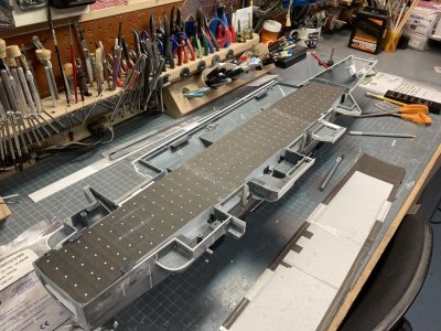
The overhead light drawing is laid on top of the hanger bulkheads to test for fit.
I had two thoughts about how the LED light strips would be used. In the ideal world both the red and white diode strips would be equal in spacing from diode to diode and I would cut the holes in the overhead based on the spacing. I would lay the strips on the overhead with the diodes lining up with the holes. I had purchased the rolls at separate times and they were not the same spacing. My second Idea was to adhere the strips to the underside of the flight deck and let the light come out through equally spaced holes. This is what I went with. I printed out the new ceiling drawing with the light locations and check for conflicts with the interior structures. I moved lights around accordingly on the computer and printed the drawing again. After verifying the final locations I converted the drawing to a cut program in the Silhouette software.
I used all the lessons that I learned making the hanger deck and cut the overhead from a .020” X 6” X 12” sheet. I t went like clockwork and after about 3 hours I had the new overhead. I went out to the model and it went into place with a couple minor modifications. To secure the position I put several pieces of angle around the lip up against the bulkheads. I then removed the hanger and assembled it out of the model. I used tape to hold things together and then added more angle pieces to gaps around the bulkhead to deck joins and then around the bulkhead to overhead joins. I only wish that I could take this whole assembly and drop it in place but unfortunately that isn’t possible. I blame the quasi- engineer who designed and built the thing.
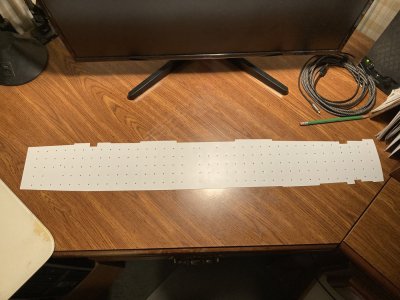
The cut out plastic overhead part. Getting the plastic to poke out of the light holes was a little tedious. If you allow the machine to cut all the way through to the mat these little parts can float around and cause a jam.
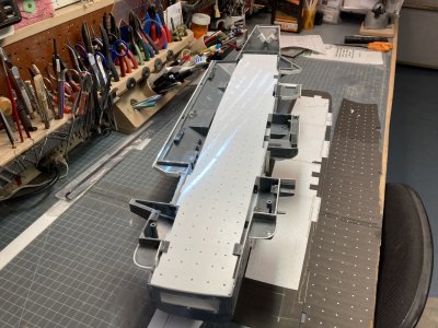
The overhead is laid in place.
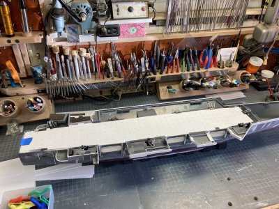
Clamping the angle locators in place for glueing.
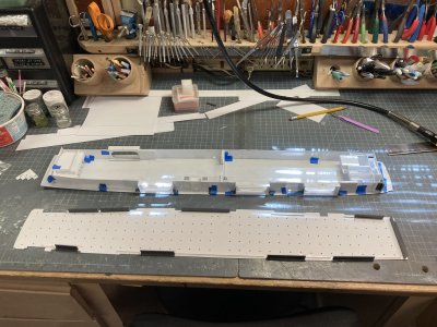
The hanger taped up outside the ship. The overhead has the angle attached to locate it when installed. I have just finished adding sections of smaller angle to finish the locators.
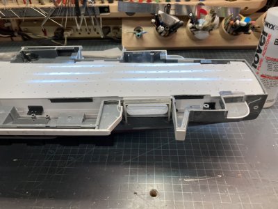
The aft end of the overhead.
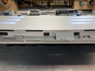
Amidships.
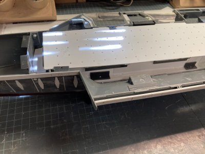
The forward end
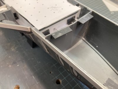
The bow.
That brings this part of the build to a finish. See you in the next post and happy modeling. I tried to download one of the drawings and it seems that when it is compressed in the website it is not very usable. I don't know if this can be fixed but I will make an online file to all my drawings and post a link later.

The overhead light drawing is laid on top of the hanger bulkheads to test for fit.
I had two thoughts about how the LED light strips would be used. In the ideal world both the red and white diode strips would be equal in spacing from diode to diode and I would cut the holes in the overhead based on the spacing. I would lay the strips on the overhead with the diodes lining up with the holes. I had purchased the rolls at separate times and they were not the same spacing. My second Idea was to adhere the strips to the underside of the flight deck and let the light come out through equally spaced holes. This is what I went with. I printed out the new ceiling drawing with the light locations and check for conflicts with the interior structures. I moved lights around accordingly on the computer and printed the drawing again. After verifying the final locations I converted the drawing to a cut program in the Silhouette software.
I used all the lessons that I learned making the hanger deck and cut the overhead from a .020” X 6” X 12” sheet. I t went like clockwork and after about 3 hours I had the new overhead. I went out to the model and it went into place with a couple minor modifications. To secure the position I put several pieces of angle around the lip up against the bulkheads. I then removed the hanger and assembled it out of the model. I used tape to hold things together and then added more angle pieces to gaps around the bulkhead to deck joins and then around the bulkhead to overhead joins. I only wish that I could take this whole assembly and drop it in place but unfortunately that isn’t possible. I blame the quasi- engineer who designed and built the thing.

The cut out plastic overhead part. Getting the plastic to poke out of the light holes was a little tedious. If you allow the machine to cut all the way through to the mat these little parts can float around and cause a jam.

The overhead is laid in place.

Clamping the angle locators in place for glueing.

The hanger taped up outside the ship. The overhead has the angle attached to locate it when installed. I have just finished adding sections of smaller angle to finish the locators.

The aft end of the overhead.

Amidships.

The forward end

The bow.
That brings this part of the build to a finish. See you in the next post and happy modeling. I tried to download one of the drawings and it seems that when it is compressed in the website it is not very usable. I don't know if this can be fixed but I will make an online file to all my drawings and post a link later.
Last edited:
- Joined
- May 8, 2021
- Messages
- 53
- Points
- 78

1-350 Scale USS Enterprise CVN-65 - Google Drive
 drive.google.com
This is the fourth pat of this post. With the link above you will gain access to my google drive file for my Enterprise build. There are files with all the drawings, scale plans, photos, and the studio 3 files to cut your own parts if you would like to try.
Last edited:


