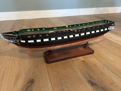
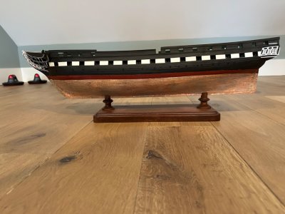
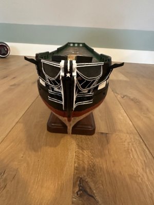
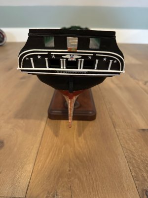
Thank you Allan. Being a novice at some of the terminology used in ships of the age of sail, could you enlighten me as to the meaning of spirketting and quickworks and the difference between them. It seems the dictionary says they are essentially the same. Whatever the case may be, I am “relieved” that they are correct on my model.Dr. Herzog responded and basically these are bolts that went through the spirketting and quickwork inboard, the frames, and outer planking in lieu of treenails from both inboard and outboard. Looking at your photo again it is great to see you have the thickness of the quickwork less than that of the spirketting. This is often missed by many folks, myself included in my earlier builds.
Allan
-

Win a Free Custom Engraved Brass Coin!!!
As a way to introduce our brass coins to the community, we will raffle off a free coin during the month of August. Follow link ABOVE for instructions for entering.
-

PRE-ORDER SHIPS IN SCALE TODAY!
The beloved Ships in Scale Magazine is back and charting a new course for 2026!
Discover new skills, new techniques, and new inspirations in every issue.
NOTE THAT OUR FIRST ISSUE WILL BE JAN/FEB 2026
You are using an out of date browser. It may not display this or other websites correctly.
You should upgrade or use an alternative browser.
You should upgrade or use an alternative browser.
Model Shipways USF Constitution
- Thread starter kingkahn1950
- Start date
- Watchers 14
Kahn
Learning the terminology can be like learning a foreign language at times. The following is from the dictionary portion Steel's The Elements and Practice of Naval Architecture. The spirketting and quickwork scantlings for various size ships and for each deck can be found in the Establishments, as well as the folios in The Elements and Practice of Naval Architecture. Both sets can be found in Scantlings of Royal Navy Ships.
From Steel

Note that it extends to the lower sills which are the lower cross pieces that makes up the gunports.

The picture below is from Peter Goodwin's The Construction and Fitting of the English Man of War, page 44
The quickwork is the thinner planking above the spirketting.
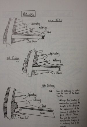
I hope this is useful to you.
Allan
Learning the terminology can be like learning a foreign language at times.
From Steel

Note that it extends to the lower sills which are the lower cross pieces that makes up the gunports.

The picture below is from Peter Goodwin's The Construction and Fitting of the English Man of War, page 44
The quickwork is the thinner planking above the spirketting.

I hope this is useful to you.
Allan
Thanks so much for including the illustrations. Now I can see your main point about the bulwark thickness. RobKahn
Learning the terminology can be like learning a foreign language at times.The following is from the dictionary portion Steel's The Elements and Practice of Naval Architecture. The spirketting and quickwork scantlings for various size ships and for each deck can be found in the Establishments, as well as the folios in The Elements and Practice of Naval Architecture. Both sets can be found in Scantlings of Royal Navy Ships.
From Steel
View attachment 457632
Note that it extends to the lower sills which are the lower cross pieces that makes up the gunports.
View attachment 457630
The picture below is from Peter Goodwin's The Construction and Fitting of the English Man of War, page 44
The quickwork is the thinner planking above the spirketting.
View attachment 457634
I hope this is useful to you.
Allan
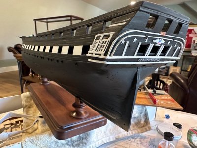
Finally back to work on the hull after taking the summer off, then going to Uganda to do a medical mission (carve a few prostates instead of stern decorations!), then recovering from shoulder surgery. Worked first on the quarter galleries which was a challenge. Read that there was a “head” just inside the aft window. Couldn’t confirm it on the ship herself because it was closed to visitors the day I made it to Boston. Nevertheless, I installed one on each side with a copper lid. The photo shows a slight copper reflection in the window. Barely visible, but it was fun trying. At least I know it’s there and the officers appreciate it. 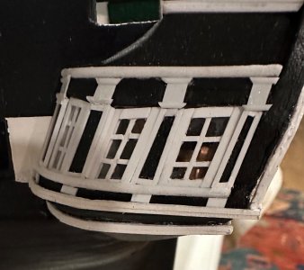
I had difficulty finding the correct angular ion of the rails and stiles of the windows and then used styrene to complete the trim. The styrene (half rounds) that required curves was difficult to clamp to the superstructure except using rubber bands helped along with a spot of super glue.
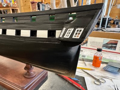
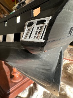
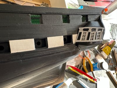
Then I added the molding trim for the stern. The kit comes with very fragile wooden laser cut pieces and I decided to try to sand them. Well using finger pressure on the pieces while sanding small sections at a time worked.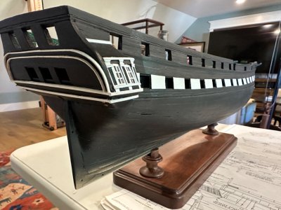

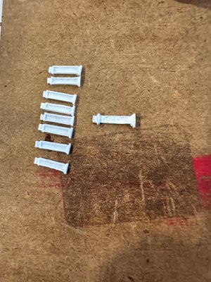
Finally I added the decorative details. The kit comes with Britain’s castings for the columns but they were not very complete and looked worse when painted, so I constructed the columns out of styrene according to the Hunt practicum. I’m going to install the three port lids after I copper the hull so the lids which are vulnerable to breakage will avoid injury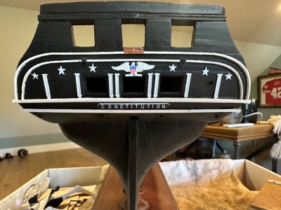

Now starts the next challenge : the bow with all of its compound curves.

I had difficulty finding the correct angular ion of the rails and stiles of the windows and then used styrene to complete the trim. The styrene (half rounds) that required curves was difficult to clamp to the superstructure except using rubber bands helped along with a spot of super glue.


Then I added the molding trim for the stern. The kit comes with very fragile wooden laser cut pieces and I decided to try to sand them. Well using finger pressure on the pieces while sanding small sections at a time worked.


Finally I added the decorative details. The kit comes with Britain’s castings for the columns but they were not very complete and looked worse when painted, so I constructed the columns out of styrene according to the Hunt practicum. I’m going to install the three port lids after I copper the hull so the lids which are vulnerable to breakage will avoid injury


Now starts the next challenge : the bow with all of its compound curves.
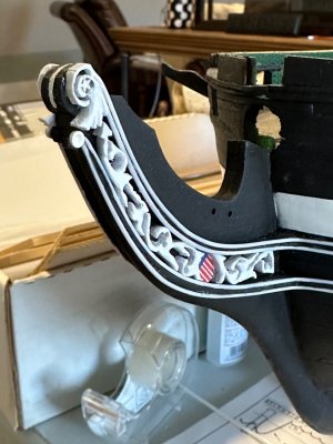
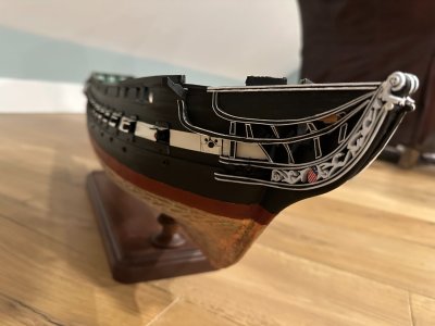
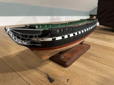
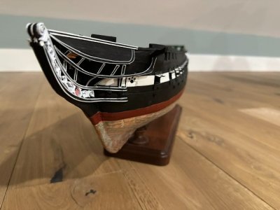
I installed the cheek rails P and S after attaching .04” half round white trim in styrene to the edges as described in the Hunt practicum. Then came the carvings which I cut out on a scroll saw with a 5-0 blade and trimmed it down further with #11 knife blade and files. The practicum described using three laminated pieces of .04” thick sheet styrene. It was my first attempt at such a carving. I’m sure etching brass sheet or a 3-d printer would come out better, but I am satisfied with my efforts. The most difficult part was the third rail (the long one that goes from the cat head to the stem). It’s compound curve and on my third attempt I was happy with the pieces. The second rail (above the third rail) was a 2 dimensional structure and was more straightforward to fashion and install. Finally I put together the grating and the heads and installed the top rail. The top rail is actually a lamination of three strips of 1/32” thick basswood with a “spacer” of 1/64” styrene between each layer. That way the rail maintains the edge triple bead that is consistent with the rail on top of the bulwarks. I painted the edge of the first and third bead to create the white trim. 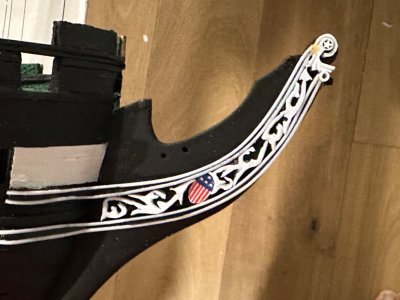
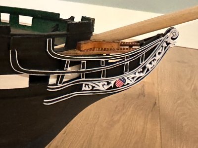
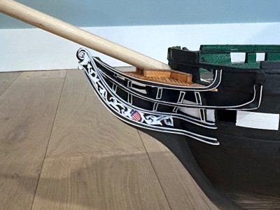
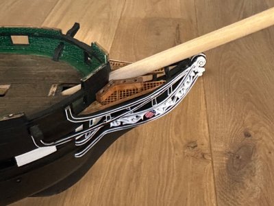
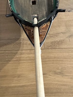
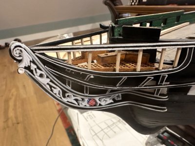
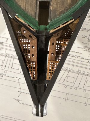
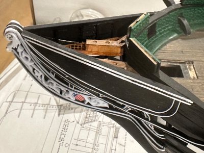
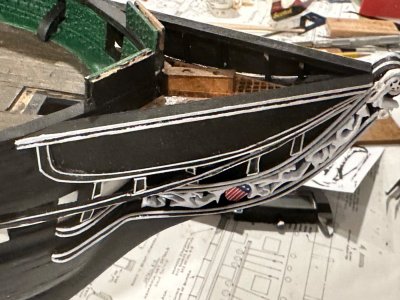


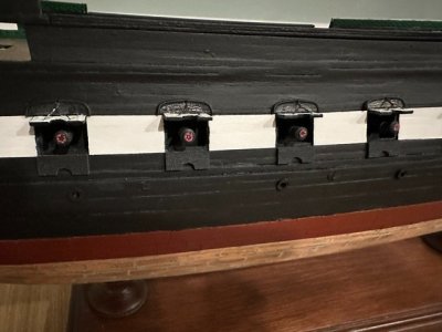
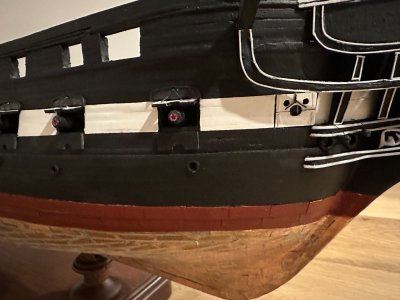
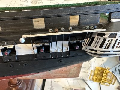
In the New Year I completed the gun deck gunports (dummy cannon) and decided to leave them open except for the bridle port which doesn't have a gun. I used very fine steel wire for the pull. I used Sketch up to print red tampions to glue into the end of the gun barrel. The star on the tompions was a little large for the scale, but at least I could see it is a star. Started on the chain plates on the mizzen channel and quite a lot of soldering left to do to finish the chain plates for the main and the foremast channels.


Last edited:
Another 6 weeks have passed and I was able to finish the chain plates and small parts needed for anchor stowage and studding boom brackets on the fore channel. Finally the quarter day it’s were installed. The hull exterior is now finished. 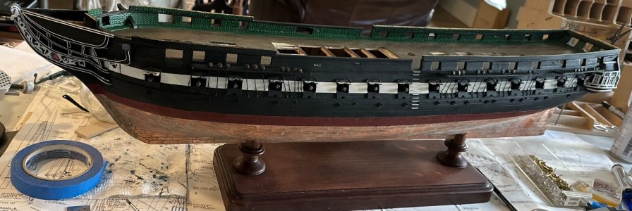
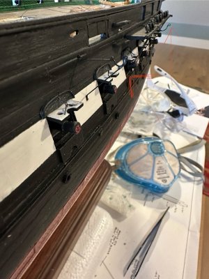
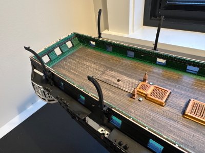
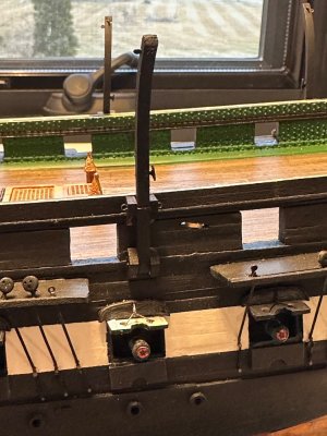
The sheaves in the bulwarks were tricky in order to get the holes on the inside to match up with the inside. The cleats on the quarter davits took some practice with the soldering iron and they probably could be even more improved upon.
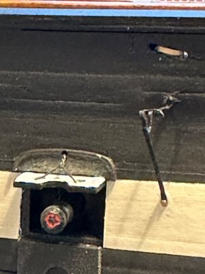
The studding boom brackets - another adventure in soldering!
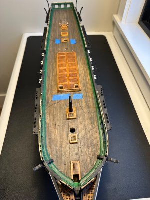
Then it was time to start finishing the spar deck.
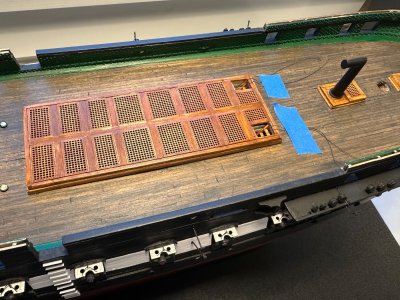
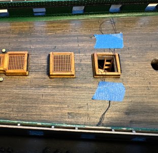
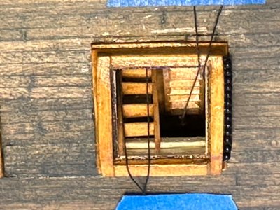
First the hatches were added. I had modified two of them to show ladders to the gun deck. Once I add the brass canopies, the black thread railing will be attached.
To be continued in a few weeks…


The sheaves in the bulwarks were tricky in order to get the holes on the inside to match up with the inside. The cleats on the quarter davits took some practice with the soldering iron and they probably could be even more improved upon.

The studding boom brackets - another adventure in soldering!
Then it was time to start finishing the spar deck.

First the hatches were added. I had modified two of them to show ladders to the gun deck. Once I add the brass canopies, the black thread railing will be attached.


To be continued in a few weeks…
Excellent work I know how challenging this model is and you have mastered it.Another 6 weeks have passed and I was able to finish the chain plates and small parts needed for anchor stowage and studding boom brackets on the fore channel. Finally the quarter day it’s were installed. The hull exterior is now finished. View attachment 508401
View attachment 508402
View attachment 508403View attachment 508404
The sheaves in the bulwarks were tricky in order to get the holes on the inside to match up with the inside. The cleats on the quarter davits took some practice with the soldering iron and they probably could be even more improved upon.
View attachment 508405
The studding boom brackets - another adventure in soldering!
Then it was time to start finishing the spar deck.
View attachment 508409
First the hatches were added. I had modified two of them to show ladders to the gun deck. Once I add the brass canopies, the black thread railing will be attached.
View attachment 508413
View attachment 508410View attachment 508411
To be continued in a few weeks…
Tony
Kurt Konrath
Kurt Konrath
Looking good, and the stove stack stands nicely in view.
I never knew ships kept a stove with stack until a few years ago, when I saw some discussion here on the forum.
I never knew ships kept a stove with stack until a few years ago, when I saw some discussion here on the forum.
Thank you so much for your kind words.Excellent work I know how challenging this model is and you have mastered it.
Tony
Thank you.Looking good, and the stove stack stands nicely in view.
I never knew ships kept a stove with stack until a few years ago, when I saw some discussion here on the forum.
Good evening. Lovely progress. Cheers GrantAnother 6 weeks have passed and I was able to finish the chain plates and small parts needed for anchor stowage and studding boom brackets on the fore channel. Finally the quarter day it’s were installed. The hull exterior is now finished. View attachment 508401
View attachment 508402
View attachment 508403View attachment 508404
The sheaves in the bulwarks were tricky in order to get the holes on the inside to match up with the inside. The cleats on the quarter davits took some practice with the soldering iron and they probably could be even more improved upon.
View attachment 508405
The studding boom brackets - another adventure in soldering!
Then it was time to start finishing the spar deck.
View attachment 508409
First the hatches were added. I had modified two of them to show ladders to the gun deck. Once I add the brass canopies, the black thread railing will be attached.
View attachment 508413
View attachment 508410View attachment 508411
To be continued in a few weeks…
Thank you so much.
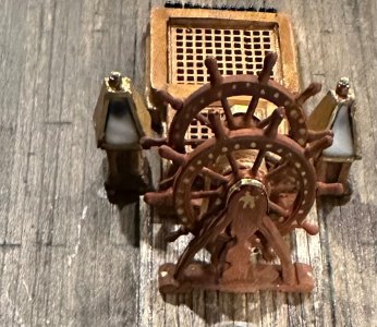
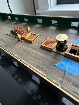
Next comes the ship’s double wheel. I’m using the Bob Hunt practicum and he rightly warns that the piece that makes up the stand (which is not included in the kit) is very difficult to make out of wood because it breaks very easily. He suggests styrene. I was thinking about the wood finish I wanted to have, so I gave it a try with wood. The problem with wood grain and curved pieces is that the curve cuts across grain lines and makes the wood susceptible to breakage. I do a lot of woodworking as a hobby and have become familiar with bentwood lamination, a technique where thin veneer like layers and glued to each other in a stack and placed in a form, which is the same shape as the desired curve. I decided to give it a try by making each half of one side of the stand in a sort of “S” curve and then carve a center post and then glue it all together. I used only two layers of 1/32” thick wood for the curve and fashioned a formed equivalent to the curve of the stand. 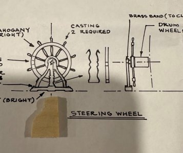
Here’s the form. I soaked two pieces of wood and used a soldering iron to curve it over the form held in a vise and then applied PVA and scotch taped it to the form for a half hour. I wrapped some tape on the edge of the form so I wouldn’t fuse the form to the assembly.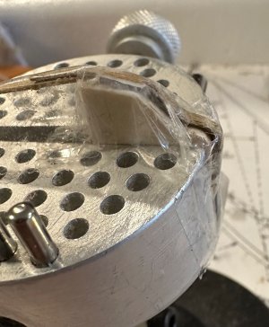
This shows the form with the thin strips bent over it and taped to the vise. The pieces come out very flexible, but hold the basic shape. I then took a length of 1/16” wood and filed the middle spindle and then glued it all together. I used some Squadron putty at the top of the stand where the sharp curve is and sanded the final curve. I drill a hole in the center of the base piece and inserted a tiny nail which strengthened the middle post attachment. The curved sides were splayed to just attach to the sides of the base.
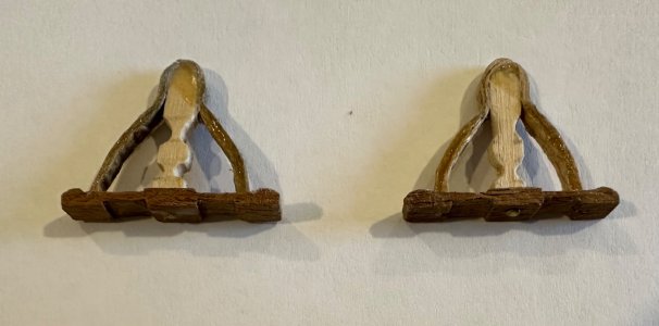
A little more sanding and then the double wheel was attached. I chose Decoart-Americana brand “Burnt Sienna” as a solid color paint to give the wheel (Britannia castings) and the stand the same color. Then a coating of water based gloss clear finish and add the rope to the drum and install.
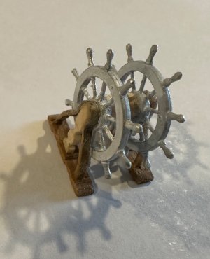
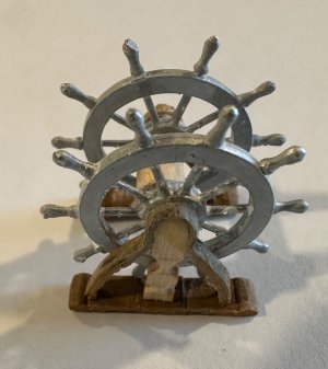
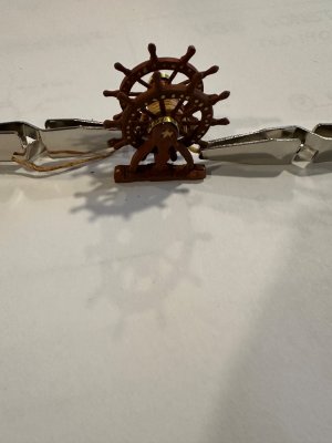
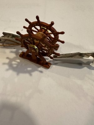
The rope which goes through the deck was glued in place with dilute PVA and the ends were stiffened with CA in order to insert them into the deck holes.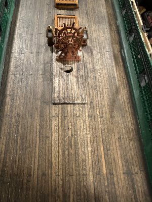
In this photo the gloss hasn’t been applied yet.
I then constructed the capstan. I used brass (paper thin) sheet to do the top and between the square holes on the topsides.
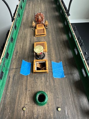

Here’s the form. I soaked two pieces of wood and used a soldering iron to curve it over the form held in a vise and then applied PVA and scotch taped it to the form for a half hour. I wrapped some tape on the edge of the form so I wouldn’t fuse the form to the assembly.

This shows the form with the thin strips bent over it and taped to the vise. The pieces come out very flexible, but hold the basic shape. I then took a length of 1/16” wood and filed the middle spindle and then glued it all together. I used some Squadron putty at the top of the stand where the sharp curve is and sanded the final curve. I drill a hole in the center of the base piece and inserted a tiny nail which strengthened the middle post attachment. The curved sides were splayed to just attach to the sides of the base.

A little more sanding and then the double wheel was attached. I chose Decoart-Americana brand “Burnt Sienna” as a solid color paint to give the wheel (Britannia castings) and the stand the same color. Then a coating of water based gloss clear finish and add the rope to the drum and install.


The rope which goes through the deck was glued in place with dilute PVA and the ends were stiffened with CA in order to insert them into the deck holes.

In this photo the gloss hasn’t been applied yet.
I then constructed the capstan. I used brass (paper thin) sheet to do the top and between the square holes on the topsides.


Been working on the carronades and the gun tackle. I felt that the wooden blocks supplied in the kit were still out of scale (1/8”) so I decided to take the plunge and go with 3/32” single and double blocks. I live right down the road from Bluejacket Shipcrafters, so I decided to use their blocks. All of their blocks are Britannia metal with mostly fine detail, and have to painted. I bought the single stropped blocks and the standard double block and am planning to fashion my own hooks out of wire. I also made my eyebolts on the carronade carriage, since the ones in the kit were also out of scale. I will need 5 tackles per gun as I’d like to show the train tackle as well, although they are not installed now on the real ship because of visitor safety. There appear to be two pair of inhaul tackle, one the base of the gun (1 inch in length to the bulwark) and one for the slide mount (5/8” to the bulwark). The latter one would need a shorter jig to fashion On the spar deck there are 20 Carronades and two long guns, so I will need three “ longer” tackles and two shorter ones per carronade gun. The long guns will need only three tackles each.
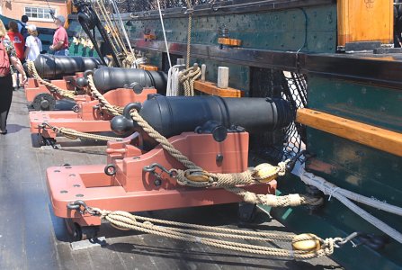
The photo from the Constitution spar deck shows a pair of inhaul tackle, a breeching line, and the eyebolt for the training - outhaul tackle.
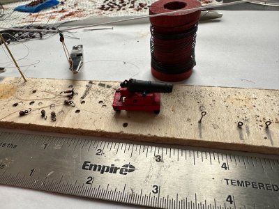
Here’s my jig with several unassembled tackle blocks all ready with hooks and the line. Also one completed tackle on the “clothesline” being stretched so it lies correctly on the model. The short and long tackle “jig” eyebolts in the lower right corner.
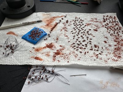
Unfortunately I’ll be doing this tedious job for weeks!

The photo from the Constitution spar deck shows a pair of inhaul tackle, a breeching line, and the eyebolt for the training - outhaul tackle.

Here’s my jig with several unassembled tackle blocks all ready with hooks and the line. Also one completed tackle on the “clothesline” being stretched so it lies correctly on the model. The short and long tackle “jig” eyebolts in the lower right corner.

Unfortunately I’ll be doing this tedious job for weeks!


