ModelShipways Norwegian Sailing Pram In Progress

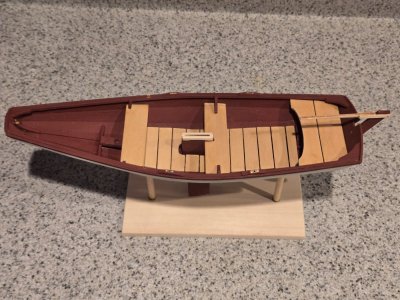
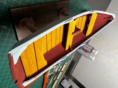
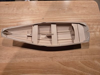
Ok, after all my ranting, everything turned out well. The rear stern sheet sits on the ledge between the two transom parts and the stern transom knee. The other part of the stern sheet is sanded and fits snug between the sheer strakes. I removed the two stern thwart knees and will replace them so they reach higher and add support to that sheet. The thwart that partially surrounds the daggerboard case needed the most sanding to fit. I had done this earlier before I relocated the daggerboard case and ended up cutting too much off. I added a piece of scrap to the end of it and now have it sanded to fit correctly. The forward thwart needed the least sanding but needed the two notches deepened. I used my dremel scroll saw to make a series of cuts into each notch and then my #11 blade to clean up the notch. I am now happy with the results.
20250324_111611.jpg

Now to move on to the floor boards.
 
The hull has been primed and is now drying. I will next sand it and paint it. While I am waiting to paint, I have been working on the tiller and re-reading the next steps. This is where I feel the instructions are very confusing.

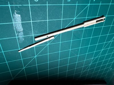
I have joined the three tiller parts and installed the pin in them. I don't have small hammer so I grasped the pin in the jaws of needle nose pliers and hit it with hammer. I think that served the same purpose. Question is, am I supposed to use same 1/16 wire for the tiller extension? Seems extension is too narrow and will split.

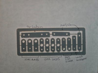
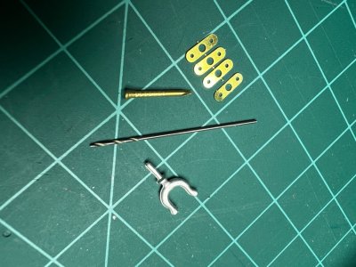
Next I started looking at installing the various hardware pieces. I found it confusing as to which photo etched brass pieces were what. So I took a picture and then went through directions and labeled them as I see them. Here is the picture. Do I have these correct?
20250325_152100.jpg.
Thanks for looking.
 
I believe you have those correct. I found that most of the holes were too small for the parts and nails and had to be enlarged. A few of the items like the oar locks I just glued into place using CA.

Rob
 
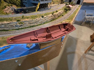
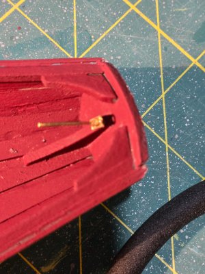
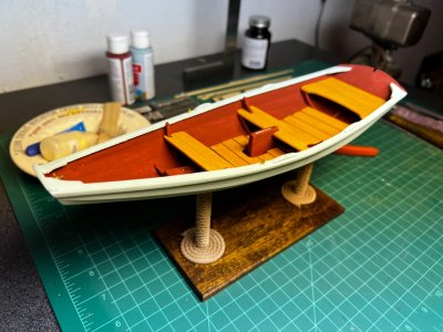
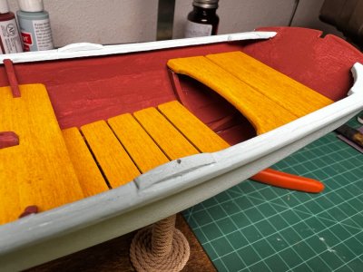
The Pram has been painted and I have started installing hardware. I installed the stay plate on the bow transom. I used a Dremel cutoff wheel to cut the brass tube to simulate the hex nut. Much easier using Dremel for this. For the two stay plates on the side, I merely glued them in the slots using CA. What is the best way to open up the holes in the photo etched parts to accept the brass nails? I got tired of messing with those little pieces that I would switch to working on the mast. I glued the two halves of the square mast and started assembling the spar shaping jig. Of course like everyone else there is a fifth notched piece that is missing. I will try to make one from the scrap wood. Did others do this or just omit one and if so which hole did you leave empty?

Here are pictures of the painted hull.
20250327_103209.jpg20250327_103449.jpg

20250327_094516.jpg
 
When the directions said to check measurement at the widest point I measured exactly 3 3/4" from the outside edges of the sheer strake. Usually you would expect to do some minor sanding to fit. I have a Drexel scroll saw that I can use to cut them quickly but afraid of cutting them too short. I'll try to file them. For the stern sheets, I'll probably have to build up the knees to keep everything level.
I had to shim to get the stern sheets level. Wasn't a big thing and it looks good now.
 
Reading the instructions, they say it can be done with or without the bent bottom... thus there will HAVE to be a bit of extra wood somewhere to allow the kit pieces to work with either option.

Also the thing to wonder, is it better to thin the frames to 1/16" BEFORE any assembly starts?
 
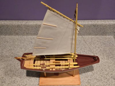
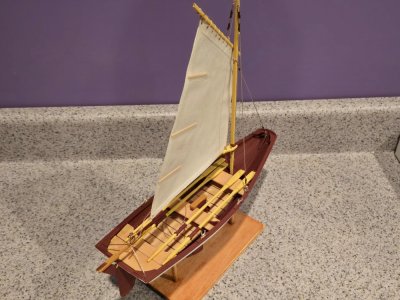
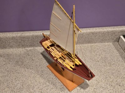
Ok, more frustrations. It's been several days since last post. I have completed gluing the flooring and the thwarts in place and proceeded working on the rudder. Used the dremel cutoff wheel to cut the tiny brass tubing pieces, and left many of them hiding somewhere on my basement floor. Tried using tweezers to sand those little devils and lost several more that took off flying to who knows where. Used CA glue to attach them to the gudgeons and attached those to the stern transom. Proceeded to work on the pintles. Why oh why did they make the brass pintle pieces so short? I saw on an older build log, don't know if it was on this site or Model Ship World, where the pintles were much longer. Also, our directions show them longer. Anyway, got those attached to the rudder also using CA. Installed the rudder on the ship and was getting ready to take pictures but realized I didn't have the tiller attached. Went to do that and the little tubing pieces fell off the gudgeons and went off to join their fellow friends. Off to the store to buy epoxy. Cut new brass tubing pieces and epoxied them to the gudgeons and now have it all together ready to take pictures.20250404_145435.jpg20250404_145512.jpg

Way too much fun.

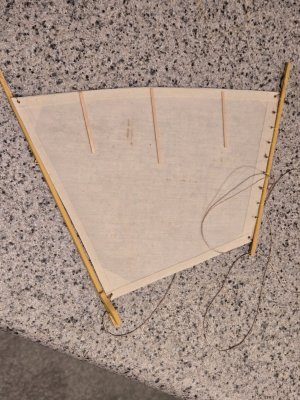
Ok, now let's move onto the mast. I glued the two mast halves together and proceeded to drill the required holes. Directions specify a hole 3/8" and one 5/16" from the top. Wow, this puts the holes nearly on top of the predrilled hole. Can this be right? Looked at the diagram of the mast on page 5 and this didn't look correct. Ok, maybe they meant from the top hole. Is this correct?
 
Ok, more frustrations. It's been several days since last post. I have completed gluing the flooring and the thwarts in place and proceeded working on the rudder. Used the dremel cutoff wheel to cut the tiny brass tubing pieces, and left many of them hiding somewhere on my basement floor. Tried using tweezers to sand those little devils and lost several more that took off flying to who knows where. Used CA glue to attach them to the gudgeons and attached those to the stern transom. Proceeded to work on the pintles. Why oh why did they make the brass pintle pieces so short? I saw on an older build log, don't know if it was on this site or Model Ship World, where the pintles were much longer. Also, our directions show them longer. Anyway, got those attached to the rudder also using CA. Installed the rudder on the ship and was getting ready to take pictures but realized I didn't have the tiller attached. Went to do that and the little tubing pieces fell off the gudgeons and went off to join their fellow friends. Off to the store to buy epoxy. Cut new brass tubing pieces and epoxied them to the gudgeons and now have it all together ready to take pictures.View attachment 511746View attachment 511747

Way too much fun.

Ok, now let's move onto the mast. I glued the two mast halves together and proceeded to drill the required holes. Directions specify a hole 3/8" and one 5/16" from the top. Wow, this puts the holes nearly on top of the predrilled hole. Can this be right? Looked at the diagram of the mast on page 5 and this didn't look correct. Ok, maybe they meant from the top hole. Is this correct?
Lovely progress
 
Ok, more frustrations. It's been several days since last post. I have completed gluing the flooring and the thwarts in place and proceeded working on the rudder. Used the dremel cutoff wheel to cut the tiny brass tubing pieces, and left many of them hiding somewhere on my basement floor. Tried using tweezers to sand those little devils and lost several more that took off flying to who knows where. Used CA glue to attach them to the gudgeons and attached those to the stern transom. Proceeded to work on the pintles. Why oh why did they make the brass pintle pieces so short? I saw on an older build log, don't know if it was on this site or Model Ship World, where the pintles were much longer. Also, our directions show them longer. Anyway, got those attached to the rudder also using CA. Installed the rudder on the ship and was getting ready to take pictures but realized I didn't have the tiller attached. Went to do that and the little tubing pieces fell off the gudgeons and went off to join their fellow friends. Off to the store to buy epoxy. Cut new brass tubing pieces and epoxied them to the gudgeons and now have it all together ready to take pictures.View attachment 511746View attachment 511747

Way too much fun.

Ok, now let's move onto the mast. I glued the two mast halves together and proceeded to drill the required holes. Directions specify a hole 3/8" and one 5/16" from the top. Wow, this puts the holes nearly on top of the predrilled hole. Can this be right? Looked at the diagram of the mast on page 5 and this didn't look correct. Ok, maybe they meant from the top hole. Is this correct?
I believe I cut the brass tubing using a small razor saw. It is actually quite soft. I agree with you 100% that the gudgeons and pintles are really difficult to work with and too short. I had the rudder fall off countless times. Instead of CA glue I used silver solder to solder the pieces together. It is actually quite easy to do and makes for a really solid join. I have to say your boat is really looking great!
 
Back
Top