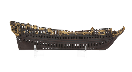
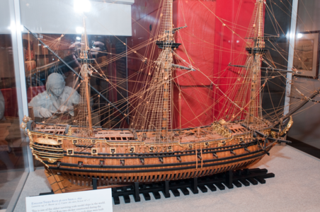
Naseby 1655 - reverse engineering the ship model

With the conclusion of this stage of exploration of the mid-17th century shipbuilding, I ought to express enormous thanks to

@- Waldemar - , without whose expertise and perseverance this could never be achieved
@DonatasBruzas , who found the 3d scan of the model and brought it to our attention
The Swedish Maritime Museum, that was so kind to make the scan available to the public

And, of course, our patient viewers and participants in this discussion.
 

some of what I've written could be considered a challenge to the 'official' symposium versions, which I'm beginning to see as being somewhat stagnant and disappointing in this particular aspect, for various reasons.


.​
Yes, as a complete amateur, myself, I am nonetheless fascinated by academic tendency to hew very closely to established orthodoxy. If no one ever dares to look at a problem from a different angle, how are we ever to glean anything new? This, for me, is the greatest value of what you and Martes are doing. The work is rooted in primary sources, but you are using tech to suss out technique. What good are computers, if we aren't going to apply them to interesting problems!

I look forward to a re-visit of the London drawings, as I was also following through that thread. Again, great stuff! Beer
 
.​

Thanks again, Marc. You've reminded me of something else. Given that what I have written and shown in this thread has the potential value of a thesis that could provoke all sorts of arguments and discussions (as has already happened), I must stress that they express my personal analysis, conclusions and views and not anyone else's. Thus, any "complaints" of any kind should therefore be addressed solely to my address and charged to my account.

.​
 
Last edited:
We have been discussing the London case with @- Waldemar - , and there are three potential points of reference, aside from the plans from Royal Collection Trust, for the 1651 building programme: this model, the Ö 3 from Stockholm that was discussed in this thread,

the SLR0217 model from RMG

1686604129219.png

and the No. 107 model from Rogers collection in USNA museum

1686604362269.png

These models represent the smaller and earlier units of the programme.
 
.​

That's right! Has anyone by any chance come across 3D scans of these models? Because it would really be desirable to analyse their design as well, before returning to London 1656 and her heavily stylised 'plans'.

Even an appropriate information as to whether the two institutions would follow the Swedes' lead and make such scans available would also help to plan the whole project more rationally.

.​
 
What Martes just stated is astounding to me given that historians have had access to these models for 200+ years. You'd think they would have been studied in the modern era by this time as well. Given the shipwrecks that have been found and recorded, it would be logical to learn how they were designed as compared to a model from that era.

From what I can tell, this field of study is still wide open and rich for new discoveries.
 
.​

There is still hope in Donatas, who is developing an ambitious, universal programme that generates ship shapes from that time and place. But he, too, must be given input data, and then these shapes must be confronted with extant models.

Alternatively, we can wait for 'official' publications, perhaps another 200+ years, if that clarifies these aspects at all or, in fact, be content with the simplified and even then already somewhat outdated Deane's Doctrine 1670.

.​
 
Last edited:
@Waldemar - thank you for your reply. Yes that is very true. But given your in-depth study and the revelations you and @Martes have had examining this model, I believe your view point on the subject was more solidly confirmed.
I just thought that a nice summary would be in order given the incredible analysis that you both conducted as you now have further evidence to back up your theory.
 
.​

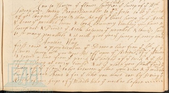
For all fans of variable floor sweeps (and likewise for unbelievers), still a relevant postscript, in the form of some passages I found in a set of documents from 1675–1695, Dimensions of ships etc. (kept in the Library of the Russian Academy of Sciences, inv. no. PIB39).

The recipes given by the author are not quite clear and precise, yet there is no doubt they are about variable floor sweeps.

Document title: A Rule for Drawing & building of ships


petrb_039_105.jpg.121e29476a1f711aa15bb05f8a8d3774.jpg


And the somewhat modernized transcription:

[…]

How to shorten the floor sweep at the head or the sweep of the breadth

Sweep your sweep proportionable to the scale to be the biggest of your longest sweep & then set off the thwart sweep in the arch & draw the parallel lines & look how many timbers you have to sweep out & divide the arc between the parallel & thwart sweep to so many parallels & it will give you the sweep for every timber.

Another way

First raise a perpendicular then draw a line from the length of the floor sweep which you must set off upon your straight […] of the floor & extend a line from there, prick to the height of the tuck & then set off the rising at every timber; & at that place you shall find the sweep of the floor to lye between the line you draw & the middle line of your bend & for the like you must do by setting the height of your gripe of your middle line then work as before.


[…]

Another way for drawing or building as was practiced by sir Phineas Pett

[...]


petrb_039_108.jpg.30af8c6b6aedbb5559bad0f7c99e56dd.jpg


Another way to sweep the midship bend. The sweep of the wrong head is ¾ of the height of breadth [too large for the floor sweep!]. The reconciling sweep is twice the first [i.e. floor] sweep. The sweep under the breadth 2/7 of the breadth. The sweep above the breadth is as 33 is to 39 so in the whole breadth which divided in half as was for each side.

[Sample dimensions:]

Breadth of the ship: 32-0
Ditto floor: 10-8
Sweep of the floor head: 12-6
[too large for the floor sweep!]
The lower breadth sweep: 8-0
Above breadth ditto: 16-0
Reconciling sweep: 18-1½


[...]


Thank you,
Waldemar Gurgul

.
 
Last edited:
@Waldemar thank you for this update on how the floor sweep may have been conducted. I'm very very new in this field and some of the terminology and systems used to design ships is unknown to me.

Should time permit, could you post a simple drawing (even hand drawn) of both techniques along with the math. I greatly appreciated the results of both methodologies but I'm having a hard time with coming up with the numbers.

Possibly posting a link to an introduction to ship design of this era may be less demanding on you and I can study it to gain a greater understanding of your discoveries. The discovery of techniques used by 15th-16th Century ship designers/builders through your investigations is fascinating as it has peaked my interest. I never realized the amount of mathematics used to design ships of this era.

Coming from a very technical background and having had to many times conduct my own investigations into complex problems, I greatly appreciate the time and effort that others like yourself put in to come up with the "proofs" needed to back new or old design theories.

Thanks!
 
Should time permit, could you post a simple drawing (even hand drawn) of both techniques along with the math. I greatly appreciated the results of both methodologies but I'm having a hard time with coming up with the numbers.

???

Sample drawings can be already found in this thread (and some other for that matter). As for the math, the equations for the straight sections, circles or ellipses can be found in probably all engineering manuals. But why math at all if you declare having a hard time with the numbers? Frankly, I'd rather get on with the next project than create an endless chain of mathematical equations, reminiscent of the source code of some computer program that nobody will even look at anyway.

.​
 
Dear @Waldemar,
Thank you for your speedy reply.

Maybe its just me, but quite honestly I didn't understand the instructions given by the 15th Century designers.
Again I'm not versed at all in this subject matter and it is quite confusing at the present time.

Basic geometry is a no brainer, but interpreting the instructions and associated variable floor sweep steps is confounding at the moment. That's why I was hoping for a link or suggestion to where I may learn more about the design techniques.

Thank you for your input into this topic as it is greatly appreciated. I'll go back into this thread and try to pull out what I can.
In time, I know I'll eventually I'll have that "ah hah" moment. :)
 
Back
Top