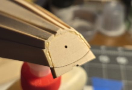
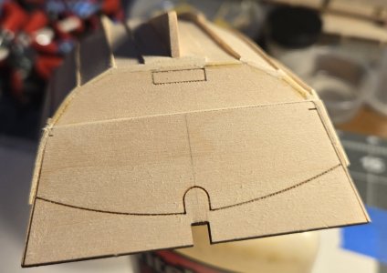
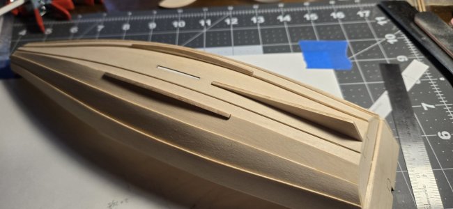
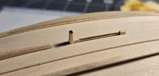
• Win a Free Custom Engraved Brass Coin!!!
    As a way to introduce our brass coins to the community, we will raffle off a free coin during the month of August. Follow link ABOVE for instructions for entering.

Norwegian Sailing Pram Build

Joined
Jun 5, 2025
Messages
22
Points
48

Location
Staten Island, NY
I am now working on my second ever wooden ship (boat) build. My first build was the Grand Banks Dory, part of the Shipwright of Old trio.

I started about 4 weeks ago. Three weeks ago I had a hip transplant, which delayed further progress. I can finally sit for more than 10 minutes at my work table.

I am trying to apply what I learned during the Dory build, and from reading other Pram build logs.

Lesson One: Sand, seal, sand, seal,... We will see how well I did with sanding and sealing when I finally apply paint.

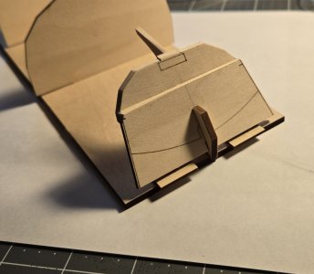
I added the bow and transom knees, and aligned and attached the upper transom. Pretty confident I was able square them up well.
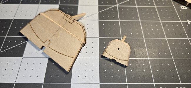
001 Bow and Transom Step 1.jpg

Next up was beveling the edges. I made the cuts around the center tab at the bottom of the transom, per instructions. Further comment on that later.
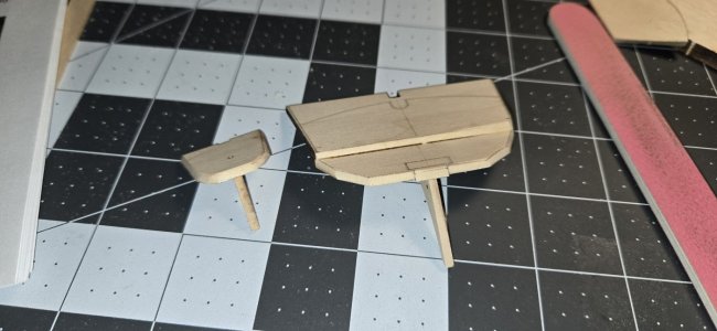
002 Bow and Transom Step 2.jpg

I eased the edges of the knees, and drilled through the hole in the bow through the bow knee.
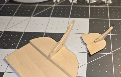
003 Bow and transome Step 3.jpg
It took three tries to finish drilling out the hole through the bow knee. As gently as I went I split the knee twice. Each time repaired with CA. Will probably need to consider some sort of backing or jig for any future such efforts.

I set up the Building Board, per instructions, and placed the bow and transom.
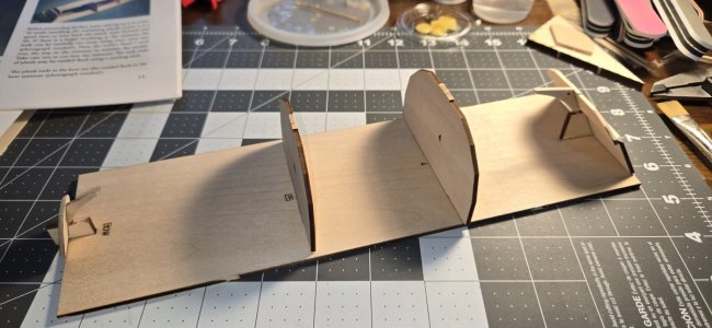
004 Building Board 1.jpg
Since the transom brace is NOT glued in place the transom wobbled, making planking alignment an issue.
UPDATE: An issue I had with the building board was the misalignment of the two forms. First, the tabs of the forms were longer than the slots in the board. I had to judiciously sand down the ends, slowly and evenly, to make the boards fit. Snugly. Second, the boards did not stand square. To remedy this I sued a file to sand one top edge and the opposite lower edge of the slot. Using the above image, form 25 is leaning aft. To help it align vertical I sanded down the top long edge on the bow side, and the bottom edge on the stern side. That allowed me to align the forms vertically without opening the slot too much. The snug fit from right to left helps keep the form in place.

I glued two spacers (left over from the Dory build) to the building board to fill in the gap and steady the transom. Not perfect, but it helped.
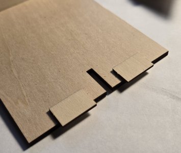
005 Building Board 2.jpg006 Building Board 3.jpg

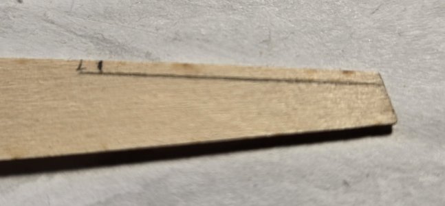
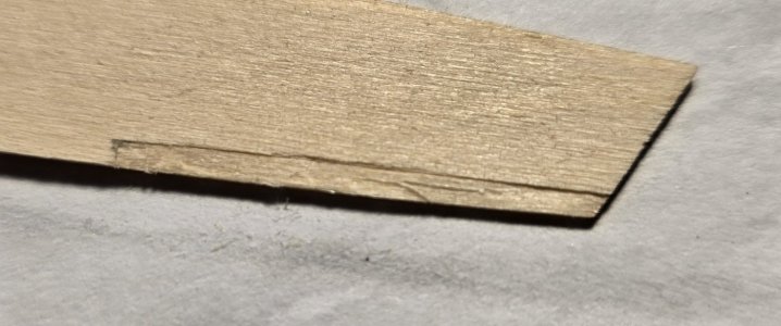
Time to bevel the outboard edges of the bottom planks.
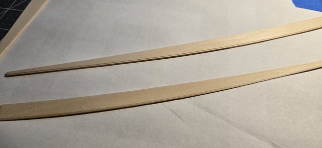
007 Bottom planks with - without beveling.jpg
The top planks has not been beveled, the lower planks beveled.

I next soaked the bottom planks in hot water for about ten minutes, then formed them on the building board.
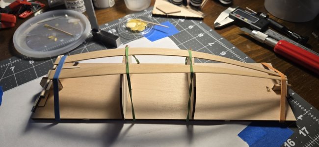
008 Bottom Planks soaked and drying on form 1.jpg

Following the instructions to have the fore ends of the bottom planks touching, with a slight overhang at the stern, I left the bottom planks to dry.
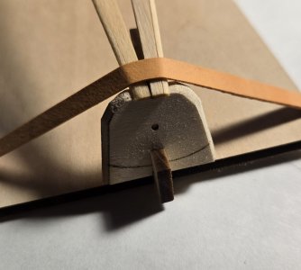
009 Bottom Planks soaked and drying on form 2.jpg010 Bottom Planks soaked and drying on form 3.jpg

Once the bottom planks were dry, I sanded both sides of each plank with progressively finer sanding boards, until they were very smooth to the touch. Each were then sealed, and held to the building board again, to ensure they maintained their bend. I repeated the sanding and sealing one more time, then one final sanding with a 220/240 sanding board. Once finally dry, I glued the two boards to the stem and transom.
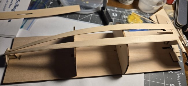
011 Bottom Planks after sanding sealing sanding.jpg
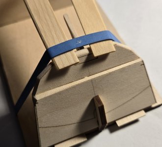
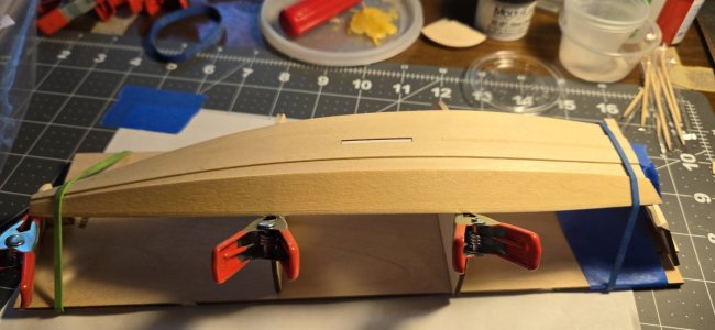
UPDATE: Due to there being some spring in the bottom planks, still, the transom and its brace kept popping out of its slot. To remedy, I placed clamps at the end of the board, effectively wedging in the transom and its brace. To maintain the alignment of the stern knee to where the keel plank would lay (I forgot to take a picture) I clamped a toothpick (cocktail stick) to the inboard side of the transom. About 3/4" to 1" stood up above the bottom planks. Using a rubber band around the toothpick, and pulling it sternward, I used it as a lever to align the transom to the point where the bottom of the knee was level with the bottoms of the bottom planks.

I repeated the soaking, sanding, and sealing process to the keel plank, and secured it to the building board to dry.
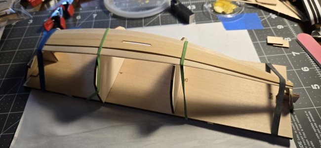
012 Keel Plank soaked and drying.jpg

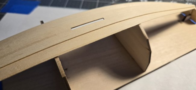
An issue I noted in several Pram builds was the gap between the keel plank and the bottom of the transom. I do not know if the tab at the bottom of the transom is too short, or it was beveled too much. I cut a shim from the scrap wood from the planking sheet, to fit the width of the gap, and as deep as the transom front to back, and glued in place. I believe once the pad is placed for the lower gudgeon, the shim should be invisible.
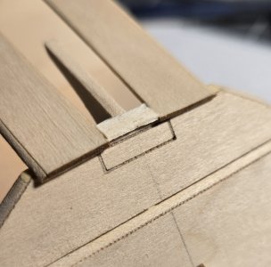
013 Spacer placed between bottom planks.jpg
Before I glue down the keel plank, I will sand the shim flush to the surface of the bottom planks. When I trim the aft ends of the bottom and keel planks the shim will get sanded flush with the ends of the planks and transom.

The keel plank glued to the bottom planks.
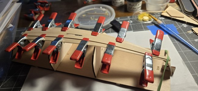
014 Keel Plank glued in place.jpg

With the keel plank drying, you can see how the shim fills the gap between the transom tab and the plank.
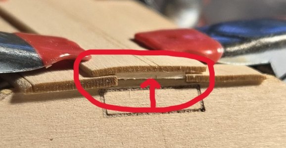
015 Spacer filling gap between bottom planks and keel plank.jpg

I thought I had sanded the shim enough. The warp of the keel plank says otherwise. I think a little filler may be in store once the outboard transom has been finished flush.

This weekend I will start the rest of the planking.

The metal fabricating will have to wait until my hip heals a bit more. I need to clear all of the auto parts and associated sundry from my work bench. I am currently using a portable work table in my dining room. Not enough room to work with soldering irons and such.
 
Last edited:
More work than expected working on ONE garboard strake. Then, isn't that always the case, with something?

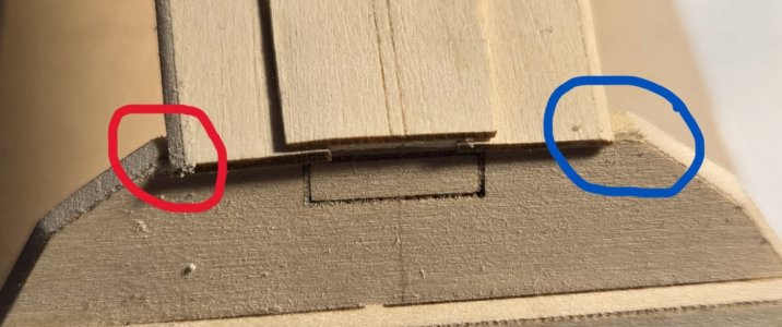
Lining up the starboard garboard plank I found the bow and stern transom edges needed some sanding. Each had 'shoulders' beyond the outboard edges of the bottom planks.
015A Sanding Transom to better match the incoming Garboard Planks.jpg
Blue: Before sanding; Red: After sanding

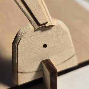
Bow transom after sanding
015B Sanding the Bow Transom to batter match the incoming Garboard Planks.jpg

Next up was making the rabbets on the lower ends of the garboard plank. I measured out the 'one foot' scale length, made stop cuts along the length and end of the rabbet. Using a #11 blade and a chisel point I trimmed away the excess. After the picture was taken I did a little more scraping with the chisel blade to deepen the rabbet.
016 Rabbets Marked on Garboard Planks.jpg017 Rabbets Cut from Garboard Planks.jpg

Besides the transoms needing some sanding to match the garboard planks, the build board forms also needed some sanding.
019 Build Board Frames sanded to match Bottom Plank angles.jpg
The sanding was just enough to maintain the angle of the edge, but also just enough to continue the slope of the beveled bottom plank along the slope of the form.

The garboard plank soaked and drying on the build board.
020 Garboard Plank Soaked and drying on form.jpg

I checked the alignment at the stern and bow transoms to see how the rabbets worked out. I was quite pleased that the alignment was pretty good on the first try.
021 Rabbet in Garboard Plank Nestling in Nicely to the Bottom Plank.jpg
Not perfect, but pretty good. No doubt with more experience I will get it better in the future.

More carpentry skills to use. Aligning the bow and stern ends of the garboard plank to the transoms I found the bottom edge of the plank to stand very proud from the bottom plank.
022 Garboard Plank standing a Little Too Proud against the Bottom Plank.jpg

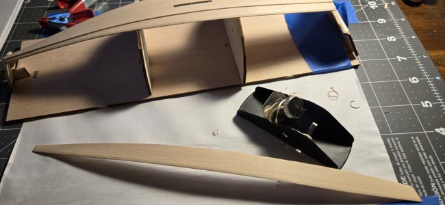
Time to break out the mini-plane and do some trimming.
023 Shaved down the Garboard Plank to match the Bottom Plank Bevel.jpg

With the garboard plank aligned on the form, I made a pencil line from the inside to mark the outer edge of the bottom plank. I knew this was not the destination of the trimming, but a reference line to guide my hand. After several back and forth passes with the plane and checking the alignment, I finally got to a point where I was satisfied with the rough edge of the plank. I then sanded the edge of the garboard plank smooth, as well as matching the contour of the bevel line on the bottom plank.

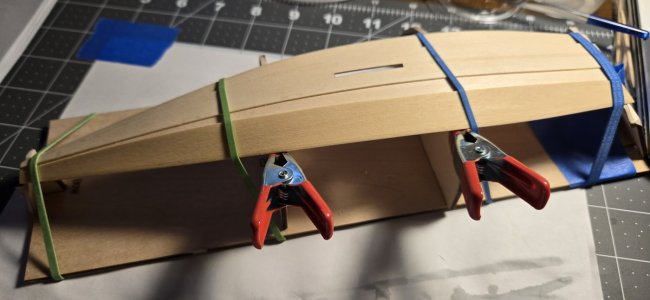
Satisfied with the final outcome, time to sand the surfaces and seal the plank. The sanding process straightened out the plank a bit. The sealer gave the plank enough flexibility that I was able to bend it to the form, clamp it, and wait for it to dry. I will repeat this once or twice more until the surface is as desired. Then on to the port side garboard plank. Finally, rinse and repeat for the second strake planks and the sheer planks.
024 Garboard Plank Sanded Polished and Sealed and drying on the form.jpg
 
More work than expected working on ONE garboard strake. Then, isn't that always the case, with something?

Lining up the starboard garboard plank I found the bow and stern transom edges needed some sanding. Each had 'shoulders' beyond the outboard edges of the bottom planks.
View attachment 539653
Blue: Before sanding; Red: After sanding

Bow transom after sanding
View attachment 539654

Next up was making the rabbets on the lower ends of the garboard plank. I measured out the 'one foot' scale length, made stop cuts along the length and end of the rabbet. Using a #11 blade and a chisel point I trimmed away the excess. After the picture was taken I did a little more scraping with the chisel blade to deepen the rabbet.
View attachment 539655View attachment 539656

Besides the transoms needing some sanding to match the garboard planks, the build board forms also needed some sanding.
View attachment 539659
The sanding was just enough to maintain the angle of the edge, but also just enough to continue the slope of the beveled bottom plank along the slope of the form.

The garboard plank soaked and drying on the build board.
View attachment 539660

I checked the alignment at the stern and bow transoms to see how the rabbets worked out. I was quite pleased that the alignment was pretty good on the first try.
View attachment 539661
Not perfect, but pretty good. No doubt with more experience I will get it better in the future.

More carpentry skills to use. Aligning the bow and stern ends of the garboard plank to the transoms I found the bottom edge of the plank to stand very proud from the bottom plank.
View attachment 539662

Time to break out the mini-plane and do some trimming.
View attachment 539663

With the garboard plank aligned on the form, I made a pencil line from the inside to mark the outer edge of the bottom plank. I knew this was not the destination of the trimming, but a reference line to guide my hand. After several back and forth passes with the plane and checking the alignment, I finally got to a point where I was satisfied with the rough edge of the plank. I then sanded the edge of the garboard plank smooth, as well as matching the contour of the bevel line on the bottom plank.

Satisfied with the final outcome, time to sand the surfaces and seal the plank. The sanding process straightened out the plank a bit. The sealer gave the plank enough flexibility that I was able to bend it to the form, clamp it, and wait for it to dry. I will repeat this once or twice more until the surface is as desired. Then on to the port side garboard plank. Finally, rinse and repeat for the second strake planks and the sheer planks.
View attachment 539664
You are really going the extra mile with the planking. I think way beyond what most of us did. I am sure it will pay off!
 
You are really going the extra mile with the planking. I think way beyond what most of us did. I am sure it will pay off!
Thanks.

I am not a perfectionist, but when I commit I go 110%.

Over 20 years (late 60s to early 90s) of model building, about a dozen years of theatrical set and lighting design and building, I am very much into the verisimilitude of making things look like their real-life counterparts.

Cheers
 
Your story sounded like a full size building experience. - trim here, sand a bit there, make it fit at the joints…

“Next one we build, remember to leave that plank a bit full to give us some wiggle room”

- next one is always better, and easier.

J
 
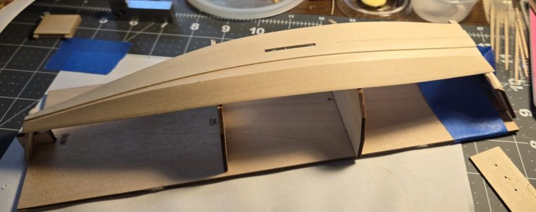
Garboard plank glued to bottom plank.
25 Garboard plank after flue dried.jpg

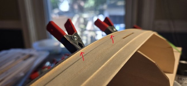
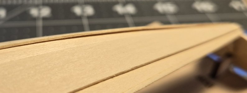
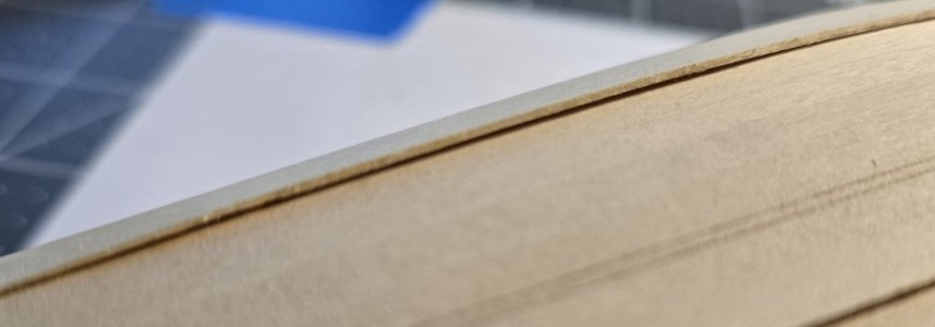
Dry fitting the garboard plank by hand, after trimming, it was looking good, the proud edge not so pronounced. After gluing the plank in place the plank was standing proud in two places. Will need to carefully trim them down.
26 Lower edge of garboard strake still showing proud.jpg
26a Lower edge of garboard strake still showing proud.jpg

While I was waiting for the garboard plank to dry on the form, before gluing it in place, I started work on other components.

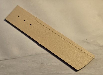
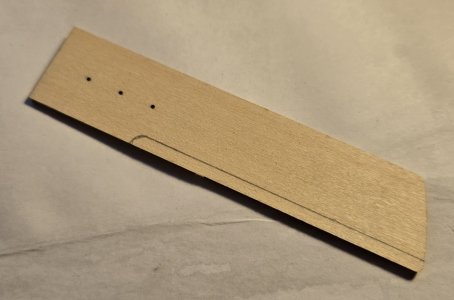
I started with the dagger board case. The spacer ends for the case were laser cut across the grain, instead of with the grain. Made them very fragile. Fortunately I was able to sand off the char from the case ends without causing any damage.
27 Work progressing on the dagger board case.jpg
Note the grain of the case side and ends in the same direction. The case would be much sturdier if the case ends had the grain going across the side piece grains. I considered fabricating new ends, but decided against it, since I was able to sand them without damage.

I cleaned up the dagger board.
I first cleaned up all of the char. Next I marked the reverse side of the board to match the guide for the bevel on the laser etched side.
28 Dagger board laser marked side.jpg28a Dagger board pencil marked side.jpg
Laser etch on the left, pencil mark on the right.

I sanded down the bevel, on both side of the board. When I was close to where I wanted it to finally be finished, I started sanding down both faces of the board. Many fittings of the board into the case to ensure a smooth passage in and out. Once I have sealed and painted the board, we'll see if I sanded enough. If not, more sanding.

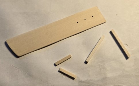
Here is the dagger board with the components for the board stop. I plan on making a lid for the dagger board case, for when the dagger board is not deployed. (Have not decided which way to finally display the pram, when completed.)
29 Dagger board and stop components.jpg

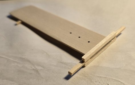
The assembled dagger board. The stop still needs to be trimmed and shaped.
30 Dagger board assembled waiting to be trimmed and finished.jpg

I figured, while I was at it, what else could I work on, while the garboard plank glue dried?
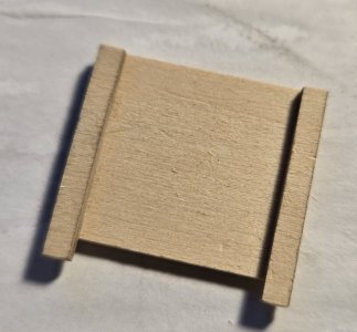
Something simple, the mast step. I glued the mast step to the mast rest. I will sand to shape once the glue is well cured.
31 Mast step and rest glued togather waiting to be finished.jpg
This is another case of where, in hindsight, I should have fabricated my own mast step and rest. The grain is going in the wrong direction.

Finally, a question for our knowledgeable readers: The dagger board has three holes, aligned vertically, and evenly spaced. I am not a sailor, but, I grew up on the Long Island Sound and was exposed to many types of power and sail boats. Can I assume the holes had a pintle that could be inserted in these holes to give the dagger board different depths, as needed, and appropriate for the sailing conditions? If I am correct, would the pintle have been most likely attached to the dagger board case with a line or chain, or either?

Edit: I did a little digging and found some answers, but not all. The holes are indeed for setting the depth of the dagger board. However, I have yet to find a satisfactory answer about actually setting the depth. Every answer, so far, indicates passing a line through the hole, knotting it, and tying it off, to set the depth. I think that is an okay answer, but unsatisfactory. It seems to me that such an arrangement is way too slow to change if the board depth needs to be adjusted quickly, such as the wind picking up suddenly.

Cheers
 
Last edited:
Great work, and hope the hip work heals up quickly so you can get back to full operations ASAP.

Now you can say your mostly original with a few after market upgrades!:)
 
Great work, and hope the hip work heals up quickly so you can get back to full operations ASAP.

Now you can say your mostly original with a few after market upgrades!:)
Thanks.

I definitely have a few upgrades: Both knees replaced, with the left knee replacement "revised", i.e., a damaged prosthesis (that's another story) replaced with a newer much more extensive one, and now the hip. The right hip is expected to need replacement in about a year or two. I am hoping for two.
 
Garboard plank glued to bottom plank.
View attachment 539952

Dry fitting the garboard plank by hand, after trimming, it was looking good, the proud edge not so pronounced. After gluing the plank in place the plank was standing proud in two places. Will need to carefully trim them down.
View attachment 539955
View attachment 539956

While I was waiting for the garboard plank to dry on the form, before gluing it in place, I started work on other components.

I started with the dagger board case. The spacer ends for the case were laser cut across the grain, instead of with the grain. Made them very fragile. Fortunately I was able to sand off the char from the case ends without causing any damage.
View attachment 539959
Note the grain of the case side and ends in the same direction. The case would be much sturdier if the case ends had the grain going across the side piece grains. I considered fabricating new ends, but decided against it, since I was able to sand them without damage.

I cleaned up the dagger board.
I first cleaned up all of the char. Next I marked the reverse side of the board to match the guide for the bevel on the laser etched side.
View attachment 539962View attachment 539963
Laser etch on the left, pencil mark on the right.

I sanded down the bevel, on both side of the board. When I was close to where I wanted it to finally be finished, I started sanding down both faces of the board. Many fittings of the board into the case to ensure a smooth passage in and out. Once I have sealed and painted the board, we'll see if I sanded enough. If not, more sanding.

Here is the dagger board with the components for the board stop. I plan on making a lid for the dagger board case, for when the dagger board is not deployed. (Have not decided which way to finally display the pram, when completed.)
View attachment 539964

The assembled dagger board. The stop still needs to be trimmed and shaped.
View attachment 539965

I figured, while I was at it, what else could I work on, while the garboard plank glue dried?
Something simple, the mast step. I glued the mast step to the mast rest. I will sand to shape once the glue is well cured.
View attachment 539966
This is another case of where, in hindsight, I should have fabricated my own mast step and rest. The grain is going in the wrong direction.

Finally, a question for our knowledgeable readers: The dagger board has three holes, aligned vertically, and evenly spaced. I am not a sailor, but, I grew up on the Long Island Sound and was exposed to many types of power and sail boats. Can I assume the holes had a pintle that could be inserted in these holes to give the dagger board different depths, as needed, and appropriate for the sailing conditions? If I am correct, would the pintle have been most likely attached to the dagger board case with a line or chain, or either?

Edit: I did a little digging and found some answers, but not all. The holes are indeed for setting the depth of the dagger board. However, I have yet to find a satisfactory answer about actually setting the depth. Every answer, so far, indicates passing a line through the hole, knotting it, and tying it off, to set the depth. I think that is an okay answer, but unsatisfactory. It seems to me that such an arrangement is way too slow to change if the board depth needs to be adjusted quickly, such as the wind picking up suddenly.

Cheers
Looking great!

With the Dagger board case ends, you may consider using thin CA to soak into the wood to strengthen them.

Rob
 
...and, we proceed...

Process for adding the Second Strake Planks and Sheer Planks pretty much the same as the previous planks: Check alignment, sand the bevel, soak, dry on form, cut rabbets, sand and polish, seal, dry on form again, glue to hull.
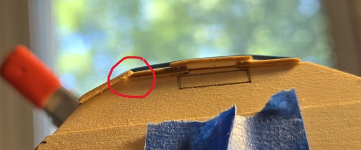
032 Lining up the planks Rabbet issue.jpg

I began to see a pattern, regarding the rabbets. I was not getting smooth transitions along the rabbets from the ends of the planks as the plank progressed along the prior plank. I found cutting the rabbets pretty easy. Cut in stops, then used a chisel blade to slowly shave off a little at a time until I was happy with the depth of the rabbet. What I began to realize is the rabbet should not only slope toward the edge of the plank, but also slope deeper as the rabbet progressed to the end of the plank and shallow as the rabbet moves away from the plank end. Something to keep in my mental catalogue of things to remember in the future.

I felt I had been doing a good job in spacing and aligning each successive set of planks. Measurements were all with a millimeter. My transom says other wise. On closer inspection I see the upper and lower transom are NOT aligned properly. Oops.
033 Upper transom misaligned.jpg

Like I said, I am pretty happy with the spacing and alignment.
034 Lining up nicely.jpg

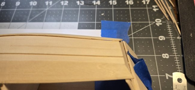
Progressing with the second strake planks and the sheer planks, I did not have to plane the lower edges of the planks to ensure appropriate alignment of the lower edges with the bevel edges of the planks below them.

Second strake planks in place. Coming together, starting to look like a boat.
035 Second strakes in place.jpg

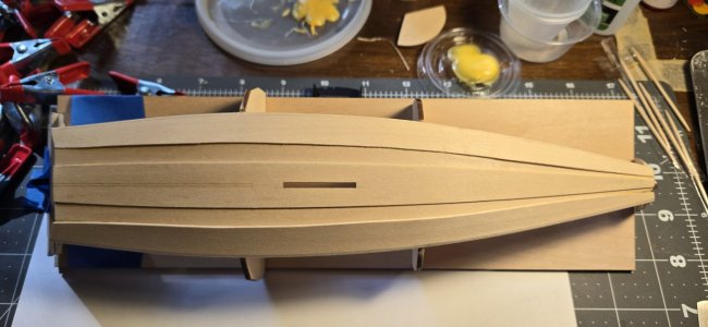
With all of the planks in place, I am pretty pleased with how they lined up at each end.

Sorry the bow transom is out of focus. What I discovered (for what I considered too late to fix) is the keel plank did not dry aligned quite on center. I have a little filling and more sanding to do on the bow, to fill those voids.
036 Sheer planks in place.jpg

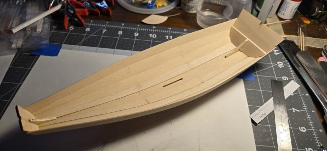
Other than the earlier comment about the transom, I am happy with the alignment of the planks. I am also please that the shim I placed between the keel plank and the transom is doing the job.
037 Planks are even port and starboard but not aligned to transom.jpg
When the time comes to trim off the excess on the bow and stern transoms, I will need to work a new arc across the stern, to match the sheer planks.

I am sure that I did not take too much off of the stern transom tab, causing the space that needed the shim. A result is the stern knee is 'hanging' a bit over the bottom of the boat. Have not decided whether to insert a shim, fill with a filler, or leave it alone. Will depend on how the stern sheets mask the sin.

Skeg and bilge keels in place.
038 Skeg and bilge keels in place.jpg
Needed to do quite a bit of sanding at the stern end of the skeg, to have it match the curve of the hull. I had to sand the fore and aft ends of the bilge keels to do the same along the garboard planks. The ends already thin made me nervous, but I managed.

Dagger board case installed.
039 Dagger board case in place.jpg
Referencing other build logs, I went with placing the case forward of the, seemingly notorious, long slot for the case supports. I created a shim to fill the resulting gap, that also doubled to wedge the case in place.

Another note to self: If I am going to jump ahead to get some other fabrication done, I better read ALL of the instructions carefully, first. The dagger board case requires two lengths of 3/32" square pieces to create the dagger board stop. What I did not realize was the inwales ALSO used the same 3/32" square strips. What the instructions failed to mention was the dagger board stop and the inwales share the same source material. IF I had cut the two pieces ONE from the each of the two strips, I would have enough to make the inwales, and the dagger board stop. Another Oops.

I am now waiting for delivery of some 3/32" square strips, and other material, so I can make the inwales.

So, now, while waiting on the inwale strips, I can start on the bottom frames and quarter knees. Still need to figure out how to use the tick strips, as only one is clearly illustrated. The seat and thwart frames will need to wait until the inwales are attached.

Cheers
 
Back
Top