-

Win a Free Custom Engraved Brass Coin!!!
As a way to introduce our brass coins to the community, we will raffle off a free coin during the month of August. Follow link ABOVE for instructions for entering.
-

PRE-ORDER SHIPS IN SCALE TODAY!
The beloved Ships in Scale Magazine is back and charting a new course for 2026!
Discover new skills, new techniques, and new inspirations in every issue.
NOTE THAT OUR FIRST ISSUE WILL BE JAN/FEB 2026
You are using an out of date browser. It may not display this or other websites correctly.
You should upgrade or use an alternative browser.
You should upgrade or use an alternative browser.
Oneida war of 1812 brig
- Thread starter Dave Stevens (Lumberyard)
- Start date
- Watchers 8
- Joined
- Dec 1, 2016
- Messages
- 6,379
- Points
- 728

COUNTER TIMBER
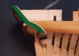
The counter timbers serve an important part on the stern of a ship. They cover the end grain of the wales, the bulwark planking and the stern planking, but they also give the stern the final shape. On classic ships the counter timbers were often elaborately carved. These timbers are difficult to install because they not only bend to the side of the hull but also twist and tuck under the lower transom. There are a couple ways to approach the making of the timbers, one way is to cut them from thin stock so they can be steam bent and each thin piece laminated to form the full thickness. Another method is to carve them to shape, which was done on the prototype model. To begin a card board pattern is made for the shape of the timber.
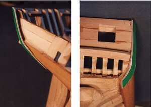
These two photos show the location, the bend and twist required for the counter timber.
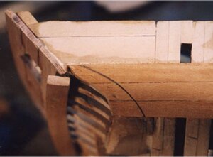
Before the pattern is removed from the hull the lower shape of the counter timber is drawn on the wales. The wales butt against the forward edge of the counter timber. You can install the counter first then cut and fit the wales to the counter, or install the wales and later cut them to fit the counter timber. The line on the wales is a close general shape. The final shape will be adjusted to match up with the actual timber once it has been made.
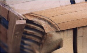
Using a small disk sander made from the bottom of a 35mm plastic film can on a Dremel the wales are cut away. A dremel drum sander and a knife were then used to finish the cut.
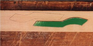
The patterns are traced on thick stock. Counter timbers are difficult to fabricate and fit to the hull. Thick stock is used because the timbers have a pronounced bend which can not be done by steam bending alone. The timbers will be cut to as close to fitting the hull and reducing the amount of bending.
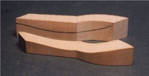
Inside edge of the timber is hollowed out with a drum sander on a Dremel or if you have a spindle sander that also works. Reduce the thickness at the center to about half the original thickness of the wood. This is a job or sand, test fit and sand a little more and fit and sand until they sit against the hull.
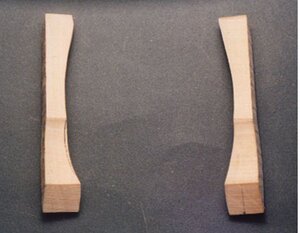
Make the counter timbers in a pair so you keep both the same shape. Every once in a while lay the pieces on the flat side and check to be sure the arc is the same on both pieces.
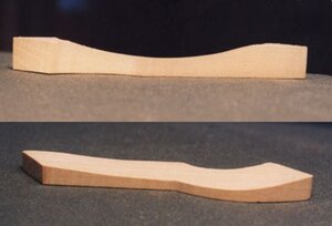
A side view shows the hollow arc on the inside of the timber, which fits against the hull. The other photo shows the timbers worked down to the final inside shape.
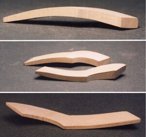
In the first photo the arched shape of the counter timber is complete. Once the timber fits the hull the outside is shaped to match the curve created by the inside arc. Both timbers are worked together to maintain the same shape. Finally the pieces are sanded down to the correct thickness. Thickness of the counter timber and the wales are the same so there is a level transition between the wales and the lower section of the counter timber. The upper part of the counter timber will have a step where the bulwark planking meets the timber.
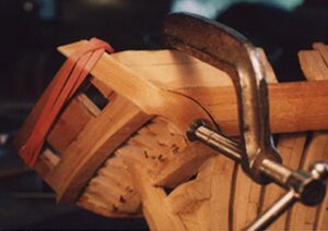
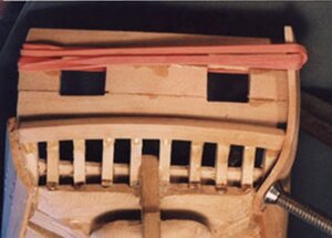
A small glass of water was boiled in a microwave, and then the timbers were dropped in the water. The timbers were left in the water until it cooled then the glass was set in the microwave and boiled again. Once the piece was pliable it was clamped to the hull. In the photo the timber would not fit tight to the wales at this point. When the counter timber cooled and dried a final fitting between the timber and wales were done. You can also see how the counter timber will define the shape of the stern at the sides.
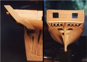
The counter timbers are now in place. When the hull is given a final sanding and finish the lower section of the counter and wales will be smooth and flush.
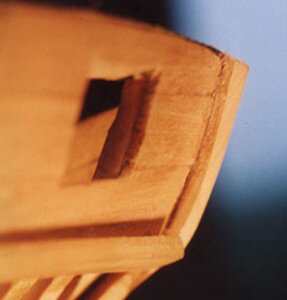
The counter timbers extend beyond the stern planking. The builder can put a half round or square molding where the timber and stern planking meet. The small molding can also continue under the transom rail.
NOTE: you will notice the space from the last frame to the stern timber was filled in with solid timbering set horizontally the sanded to blend into the bulwarks. The larger the ship the more elaborate the construction in this area. For a brig such as the Oneida solid timbering serves the purpose quite well.

The counter timbers serve an important part on the stern of a ship. They cover the end grain of the wales, the bulwark planking and the stern planking, but they also give the stern the final shape. On classic ships the counter timbers were often elaborately carved. These timbers are difficult to install because they not only bend to the side of the hull but also twist and tuck under the lower transom. There are a couple ways to approach the making of the timbers, one way is to cut them from thin stock so they can be steam bent and each thin piece laminated to form the full thickness. Another method is to carve them to shape, which was done on the prototype model. To begin a card board pattern is made for the shape of the timber.

These two photos show the location, the bend and twist required for the counter timber.

Before the pattern is removed from the hull the lower shape of the counter timber is drawn on the wales. The wales butt against the forward edge of the counter timber. You can install the counter first then cut and fit the wales to the counter, or install the wales and later cut them to fit the counter timber. The line on the wales is a close general shape. The final shape will be adjusted to match up with the actual timber once it has been made.

Using a small disk sander made from the bottom of a 35mm plastic film can on a Dremel the wales are cut away. A dremel drum sander and a knife were then used to finish the cut.

The patterns are traced on thick stock. Counter timbers are difficult to fabricate and fit to the hull. Thick stock is used because the timbers have a pronounced bend which can not be done by steam bending alone. The timbers will be cut to as close to fitting the hull and reducing the amount of bending.

Inside edge of the timber is hollowed out with a drum sander on a Dremel or if you have a spindle sander that also works. Reduce the thickness at the center to about half the original thickness of the wood. This is a job or sand, test fit and sand a little more and fit and sand until they sit against the hull.

Make the counter timbers in a pair so you keep both the same shape. Every once in a while lay the pieces on the flat side and check to be sure the arc is the same on both pieces.

A side view shows the hollow arc on the inside of the timber, which fits against the hull. The other photo shows the timbers worked down to the final inside shape.

In the first photo the arched shape of the counter timber is complete. Once the timber fits the hull the outside is shaped to match the curve created by the inside arc. Both timbers are worked together to maintain the same shape. Finally the pieces are sanded down to the correct thickness. Thickness of the counter timber and the wales are the same so there is a level transition between the wales and the lower section of the counter timber. The upper part of the counter timber will have a step where the bulwark planking meets the timber.


A small glass of water was boiled in a microwave, and then the timbers were dropped in the water. The timbers were left in the water until it cooled then the glass was set in the microwave and boiled again. Once the piece was pliable it was clamped to the hull. In the photo the timber would not fit tight to the wales at this point. When the counter timber cooled and dried a final fitting between the timber and wales were done. You can also see how the counter timber will define the shape of the stern at the sides.

The counter timbers are now in place. When the hull is given a final sanding and finish the lower section of the counter and wales will be smooth and flush.

The counter timbers extend beyond the stern planking. The builder can put a half round or square molding where the timber and stern planking meet. The small molding can also continue under the transom rail.
NOTE: you will notice the space from the last frame to the stern timber was filled in with solid timbering set horizontally the sanded to blend into the bulwarks. The larger the ship the more elaborate the construction in this area. For a brig such as the Oneida solid timbering serves the purpose quite well.
Last edited:
- Joined
- Dec 1, 2016
- Messages
- 6,379
- Points
- 728

STERN CAP RAIL
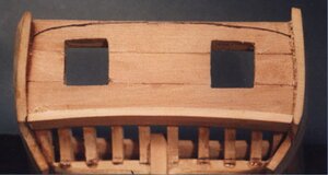
First thing to be done is to shape the top of the stern. The plans show the shape but the builder can give the top a little more or less shape according to his liking.
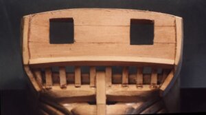
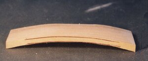
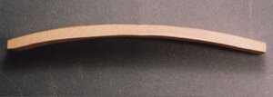
Once again the home made disk sander on the Dremel was used to shape the top of the stern.
When your satisfied with the top of the stern a tracing is made of the shape, then it is transferred to the edge of a piece of 1/4 inch thick sheet stock. The transom rail is made the same way the lower molding was made. The rail bends side to side as well as curves from front to back. Like the molding, it is quite impossible to bend a rail in two directions, so like the molding the rail is carved to shape. Starting with a piece of wood about 1/4 thick and 1/2 wide and longer than the stern, carve the arc of the rail. First carve the inside shape until it sits nice and flush on the stern. Then carve the upper side until the rail is 1/8 thick.
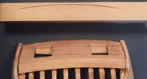
Trace the curve of the stern on to the rail piece.

Cut the rail about 3/8 wide.
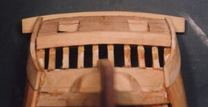
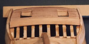
Placing the rail on the stern there should be a small overlap and enough room on the inside to cover the inside stern planking.
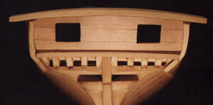
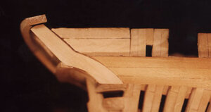
Keep adjusting the top of the stern and the transom rail until the ends of the rail sit on top of the counter timbers. The rail will extend slightly beyond the counter timbers when cut off, also the cap rail will sit below the transom rail.

First thing to be done is to shape the top of the stern. The plans show the shape but the builder can give the top a little more or less shape according to his liking.


Once again the home made disk sander on the Dremel was used to shape the top of the stern.
When your satisfied with the top of the stern a tracing is made of the shape, then it is transferred to the edge of a piece of 1/4 inch thick sheet stock. The transom rail is made the same way the lower molding was made. The rail bends side to side as well as curves from front to back. Like the molding, it is quite impossible to bend a rail in two directions, so like the molding the rail is carved to shape. Starting with a piece of wood about 1/4 thick and 1/2 wide and longer than the stern, carve the arc of the rail. First carve the inside shape until it sits nice and flush on the stern. Then carve the upper side until the rail is 1/8 thick.


Trace the curve of the stern on to the rail piece.

Cut the rail about 3/8 wide.

Placing the rail on the stern there should be a small overlap and enough room on the inside to cover the inside stern planking.


Keep adjusting the top of the stern and the transom rail until the ends of the rail sit on top of the counter timbers. The rail will extend slightly beyond the counter timbers when cut off, also the cap rail will sit below the transom rail.
Last edited:
- Joined
- Dec 1, 2016
- Messages
- 6,379
- Points
- 728

We will now proceed to the bow gun platform or raised forecastle deck. It is totally up to the builder at this point how they want to build their Oneida. A carronade provided a heck of a blast, however they were a short range weapon so the Oneida was originally designed to carry a 32 pound cannon at the bow. Woolsey argued the heavy 32 pound cannon at the bow would make the Oneida to difficult to handle so he suggested 2 more carronades. The navy department wanted the Oneida armed so i could go against anything on the lake.
This is a point often debated among model ship builders my model vs Historical correctness. Throughout the life of a war ship on the Great Lakes guns were whatever could be found or what was on hand, often guns were replaced during the life of the ship and historical records often contradict each other. My approach to the subject of the Oneida is as it was designed. The shipyard did in fact have the 32 pound cannon on hand.
What was on the drawing board and what was going on in the heads of the guys at the top is one thing what was actually built can very well be something else. i figured the top brass designed a brig with heavy metal armed to the teeth with carronades and one big 32 pound cannon for long range. So in my shipyard that is what i built.
Last edited:
- Joined
- Dec 1, 2016
- Messages
- 6,379
- Points
- 728

FORE CASTLE DECK
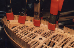
The fore castle deck sits on a ledge made up of deck clamp material because bulwark planking is to thin to take the weight of the deck plus the weight of a massive cannon. The first plank rests on top of the waterway, and notches into the first gun port sill. You will find it necessary to soak the end of the plank in hot water for a few minutes, clamp it in place and allow the wood to dry before gluing in place. The plank has a natural tendency to curve upward so the first clamp holds the plank down against the waterway, while the other three clamps bend the plank to conform to the hull.
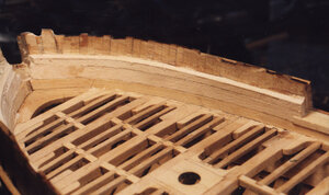
A second plank is set on top of the first one and the same steps were followed to bend and secure the plank. When the second plank is in place a measurement is taken from the main deck to the height of the fore castle. A thin plank is bent to the marks, a pencil line is drawn, and the top plank is cut down to the correct height.
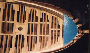
A piece of cardboard is used to get the proper shape of the bow. This will be slightly different on each ship because it depends on the builders placement of the bow timbers.
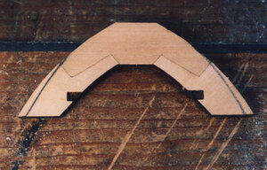
The breasthook parts are laser cut larger than needed so the card board template is used to mark out the final shape. This is a cut and fit process, you have to trim a little and try the fit, then go back and refine the fitting.
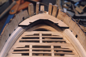
Once the part fits nice against the hull the edges are beveled to sit against the side of the hull and the breasthook is fit on top of the clamps.
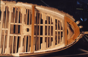
Deck beams 1 and 4 are set in place. Beam one fits against the breasthook and beam four sets directly above deck beam four on the main deck. Placement of beam number four is important because you don’t want it to obstruct the forward mast.
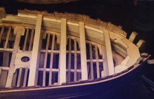
Beams two and three are now set into place. You don’t have to follow the exact layout on the plans. I moved beams two and three a little closer together. The reason being the heavy 32 pound long gun rests on these two beams, I didn’t want the gun to rest on a thinner ledge. By doing this, the knees are cut and adjusted to fit between beams. The knees provided are once again cut larger than needed to allow for fitting. Notice there are no carlings or hanging knees on the fore castle deck. Ledges are run across the deck from lodging knee to lodging knee. you can also see the thickness of the clamps the beams are sitting on.
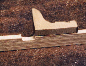
On the main deck the deck beams are set directly on top of the deck clamp. On the fore castle deck the deck beams are notched into the deck clamp.
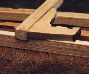
The notch is cut to a depth so the top of the beam and the knees are even.
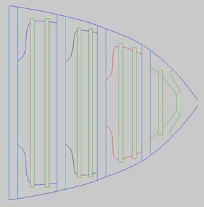
there are knees and ledges that go into the deck but there is no need to get into placing them. If you managed to build the deck the process is the same.

The fore castle deck sits on a ledge made up of deck clamp material because bulwark planking is to thin to take the weight of the deck plus the weight of a massive cannon. The first plank rests on top of the waterway, and notches into the first gun port sill. You will find it necessary to soak the end of the plank in hot water for a few minutes, clamp it in place and allow the wood to dry before gluing in place. The plank has a natural tendency to curve upward so the first clamp holds the plank down against the waterway, while the other three clamps bend the plank to conform to the hull.

A second plank is set on top of the first one and the same steps were followed to bend and secure the plank. When the second plank is in place a measurement is taken from the main deck to the height of the fore castle. A thin plank is bent to the marks, a pencil line is drawn, and the top plank is cut down to the correct height.

A piece of cardboard is used to get the proper shape of the bow. This will be slightly different on each ship because it depends on the builders placement of the bow timbers.

The breasthook parts are laser cut larger than needed so the card board template is used to mark out the final shape. This is a cut and fit process, you have to trim a little and try the fit, then go back and refine the fitting.

Once the part fits nice against the hull the edges are beveled to sit against the side of the hull and the breasthook is fit on top of the clamps.

Deck beams 1 and 4 are set in place. Beam one fits against the breasthook and beam four sets directly above deck beam four on the main deck. Placement of beam number four is important because you don’t want it to obstruct the forward mast.

Beams two and three are now set into place. You don’t have to follow the exact layout on the plans. I moved beams two and three a little closer together. The reason being the heavy 32 pound long gun rests on these two beams, I didn’t want the gun to rest on a thinner ledge. By doing this, the knees are cut and adjusted to fit between beams. The knees provided are once again cut larger than needed to allow for fitting. Notice there are no carlings or hanging knees on the fore castle deck. Ledges are run across the deck from lodging knee to lodging knee. you can also see the thickness of the clamps the beams are sitting on.

On the main deck the deck beams are set directly on top of the deck clamp. On the fore castle deck the deck beams are notched into the deck clamp.

The notch is cut to a depth so the top of the beam and the knees are even.

there are knees and ledges that go into the deck but there is no need to get into placing them. If you managed to build the deck the process is the same.
Last edited:
- Joined
- Dec 1, 2016
- Messages
- 6,379
- Points
- 728

planking up the bulwarks
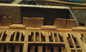
After setting the frames up there will be slight variations in the alignment of the top of the frames. Glue a piece of sandpaper to a flat piece of wood to use for sanding flat the outside of the bulwarks. The bottom of the wood piece is used to ride along the top edge of the wales to give an even sanding from top to bottom of the bulwark. The inside is not possible to sand in this manor so I left it as built except where a frame or filler piece stuck out to far. In this case I used a disk sander on the Dremel tool to bring it into alignment. Should any frame or filler piece fall short because its to thin this is really of no big concern. The planking will cover any hollows and glue will fill in the gap between the plank and the frame surface.
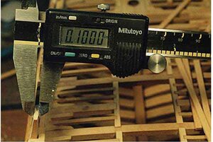
Sand down the bulwarks until they are between .090 and .100 the actual thickness is 4 to 5 inches on the real ship. You don't have to be dead on for the top of the frames because nothing will actually show. Planking covers the sides and the cap rail covers the top.
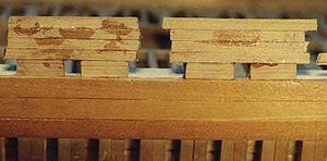
The first plank above the wale is wider than the rest of the planking. This was done to match the top of the plank to the top of the row port. Otherwise a notch would have to be cut into the bottom of the next plank. Each plank edge is cut with a slight bevel to insure a tight fit to the one next to it. At this stage of planking as you can see there is no concern to neatness, the planks were allowed to run beyond the edge of the gun port and glue from clamping ended up on the surface of the planks. The glue used on the model is epoxy and it cleans off the surface without a trace. However some glue will leave a stain or residue showing up after a finish is applied to the wood.
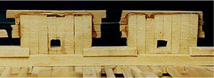
Looking from the inside of the bulwarks you can see the run over of the planking into the gun ports. By using the side of the ports as a guide, a razor saw is used to cut the planking even with the port sides. Then a little touch with sand paper or file evens everything out. Due not cut the top plank down to the frame tops. A sheer will be sanded later when the cap rail is installed.
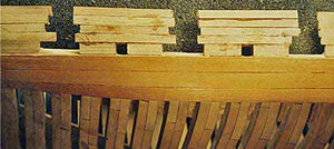
Each bulwark section is planked in the rough; once they all have been planked they are then trimmed and cleaned up.
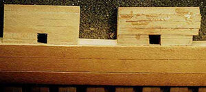
Here we see a comparison between a roughed in section and a finished one. All the surface glue is cleaned off and the planking trimmed to the edge of the gun port. By creating the row port with the planking itself, it creates a clean square port. This works out better than trying to cut them into the planking.
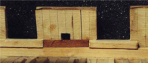
All the bulwark sections are trimmed on the sides and we are ready to plank the inside. To even out the frames, if needed, a sanding disk was used on a Dremel tool and the inside was given a light once over sanding. Here you can see a little unevenness of the frame tops. This is best left as it is, once the inside and outside planking is on, an overall sanding of the tops will be done later to even things out.
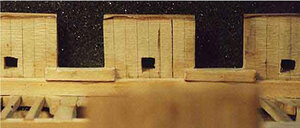
On the outside of the bulwark we started with a wider plank to match up with the top of the row port. Not so on the inside, because the waterway is slightly higher than the top of the wale. Start the inside with one of the narrower planks and cut it to fit between the sills. The sill thickness and the planking are very close to the same size, if not, you can sand down the sill to match up with the top of the plank. You want the top of the plank and the sill to match up or you will be notching the next plank to fit.
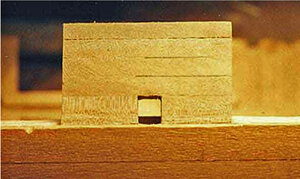
Look very close at the row port opening, looking through it you can see the first plank inside the bulwark. The plank will match up with the top of the sill, but it is slightly too high for the row port. You will need to get in there with a sharp pointed knife and cut the plank down even with the bottom of the opening.
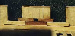
The next plank will take a little fiddling with to get it to rest square and even with the port sill and the plank below it. The end of the plank is set even with the row port and let to overhang the edge of the gun port.
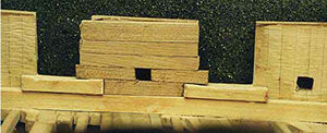
Planking on the inside, is done the same way as it's done on the outside. The top plank is the widest plank. In other words the inside is planked opposite of the outside, with the wider plank on the top, inside the bulwark, while on the outside it is at the bottom. It's a little tricky giving the inside a final sanding because you have to work around the gun port sill. Once all the planks are in place they are cut and sanded to the side of the gun ports. Again notice the unevenness at the top where the inside and outside don't quite match up. No problem, a sheer is sanded along the top before the cap rail is installed.

After setting the frames up there will be slight variations in the alignment of the top of the frames. Glue a piece of sandpaper to a flat piece of wood to use for sanding flat the outside of the bulwarks. The bottom of the wood piece is used to ride along the top edge of the wales to give an even sanding from top to bottom of the bulwark. The inside is not possible to sand in this manor so I left it as built except where a frame or filler piece stuck out to far. In this case I used a disk sander on the Dremel tool to bring it into alignment. Should any frame or filler piece fall short because its to thin this is really of no big concern. The planking will cover any hollows and glue will fill in the gap between the plank and the frame surface.

Sand down the bulwarks until they are between .090 and .100 the actual thickness is 4 to 5 inches on the real ship. You don't have to be dead on for the top of the frames because nothing will actually show. Planking covers the sides and the cap rail covers the top.

The first plank above the wale is wider than the rest of the planking. This was done to match the top of the plank to the top of the row port. Otherwise a notch would have to be cut into the bottom of the next plank. Each plank edge is cut with a slight bevel to insure a tight fit to the one next to it. At this stage of planking as you can see there is no concern to neatness, the planks were allowed to run beyond the edge of the gun port and glue from clamping ended up on the surface of the planks. The glue used on the model is epoxy and it cleans off the surface without a trace. However some glue will leave a stain or residue showing up after a finish is applied to the wood.

Looking from the inside of the bulwarks you can see the run over of the planking into the gun ports. By using the side of the ports as a guide, a razor saw is used to cut the planking even with the port sides. Then a little touch with sand paper or file evens everything out. Due not cut the top plank down to the frame tops. A sheer will be sanded later when the cap rail is installed.

Each bulwark section is planked in the rough; once they all have been planked they are then trimmed and cleaned up.

Here we see a comparison between a roughed in section and a finished one. All the surface glue is cleaned off and the planking trimmed to the edge of the gun port. By creating the row port with the planking itself, it creates a clean square port. This works out better than trying to cut them into the planking.

All the bulwark sections are trimmed on the sides and we are ready to plank the inside. To even out the frames, if needed, a sanding disk was used on a Dremel tool and the inside was given a light once over sanding. Here you can see a little unevenness of the frame tops. This is best left as it is, once the inside and outside planking is on, an overall sanding of the tops will be done later to even things out.

On the outside of the bulwark we started with a wider plank to match up with the top of the row port. Not so on the inside, because the waterway is slightly higher than the top of the wale. Start the inside with one of the narrower planks and cut it to fit between the sills. The sill thickness and the planking are very close to the same size, if not, you can sand down the sill to match up with the top of the plank. You want the top of the plank and the sill to match up or you will be notching the next plank to fit.

Look very close at the row port opening, looking through it you can see the first plank inside the bulwark. The plank will match up with the top of the sill, but it is slightly too high for the row port. You will need to get in there with a sharp pointed knife and cut the plank down even with the bottom of the opening.

The next plank will take a little fiddling with to get it to rest square and even with the port sill and the plank below it. The end of the plank is set even with the row port and let to overhang the edge of the gun port.

Planking on the inside, is done the same way as it's done on the outside. The top plank is the widest plank. In other words the inside is planked opposite of the outside, with the wider plank on the top, inside the bulwark, while on the outside it is at the bottom. It's a little tricky giving the inside a final sanding because you have to work around the gun port sill. Once all the planks are in place they are cut and sanded to the side of the gun ports. Again notice the unevenness at the top where the inside and outside don't quite match up. No problem, a sheer is sanded along the top before the cap rail is installed.
- Joined
- Dec 1, 2016
- Messages
- 6,379
- Points
- 728

what about the cap rail or the headrails how about carving the billet scroll on the stem? mounting the carronades and the 32 pound cannon
over the years those subjects got lost in cyber space and the model is long gone.
perhaps other builds will add to this build log.
so with that i must say
THE END
over the years those subjects got lost in cyber space and the model is long gone.
perhaps other builds will add to this build log.
so with that i must say
THE END
what about the cap rail or the headrails how about carving the billet scroll on the stem? mounting the carronades and the 32 pound cannon
over the years those subjects got lost in cyber space and the model is long gone.
perhaps other builds will add to this build log.
so with that i must say
THE END
Dave, thank you for this great article, you are really tempting me to place my order, only how do I sneak it by you know who?
Best,
Ed
Best,
Ed


