Plan drawing

Looks like a three tube superheterodyne receiver. No power supplies, usually batteries. LT was probably 6V and HT was probably 67V.
There wasn't a power supply as such, it was a battery set. Two Volts LT and 90 to 150 Volts HT.
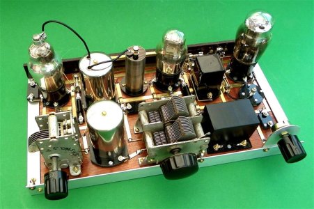
It is a TRF (Tuned Radio Frequency) RF amplifier, detector and power amplifier valves. The metal screening cans are old salt cellars, and the RF, detector and RF coils are inside them. The coils ar e RF chokes, very small -
 
Looks like a three tube superheterodyne receiver. No power supplies, usually batteries. LT was probably 6V and HT was probably 67V.
Vacuum tubes typicallyrequire a Plate Supply and of course the cathodes require a filament supply. Some plate voltages can be as high as 680V and filament was usually 6.3V but I am recalling this from my old, old brain.....we used to call the plate supply "B+".....
 
You guys didn't see the battery B1 below and to the right of V2.

Yes, but it looks like it's just there to bias the grid in the audio amplifier tube. Follow the schematic and you'll see that it never makes a complete circuit - it's always blocked by capacitors (which don't pass DC). The power comes in from the far right - one voltage for the tube filaments (LT - 2 volts) and one for power (HT - 90 - 150 volts).
 
what the old-time draftsmen could do with pen and ink remains today truly impressive.
I love looking at those types of old 19th century and earlier mechanical drawings. They add lots of nostalgia, character and life to an otherwise 'blah' presentation... something very unique that our modern CAD systems will never be able to fully replicate via keyboards, mice and electron blips on a computer screen. As for the tube schematic, I'm staying out of that one. I remember my dad testing tubes at the grocery store (I think it was Safeway, but not sure), but when I got into electronics, in the Navy, we finally had black magic rocks, PNP and NPN. :)
 
Last edited:
Thanks for replies on the blueprint. This vintage replica that I designed and built represents an era far earlier than 6.3 Volt heaters.
It is a battery set, and the valves are directly heated, dating back to the late 1920s or early 30s.
The filament voltage was two Volts obtained from a 2 Volt rechargeable lead acid battery.
The HT for these valves was officially 120 Volts from a block battery composed of 80, 1.5 Volt dry cells connected in series. The small battery on the left of the output valve is a modern CR2032 button cell, supply negative grid bias to the output valve. No current drain at all.
I trained as a merchant navy radio officer in the late 50s, qualifying in 1960 when ALL the equipment was built with valves - transistors etc were not even in the syllabus.
I am pleased to see so much interest has been shown, usually, I just get bank stares with eyes glazing over if I show it anyone. It works very well.
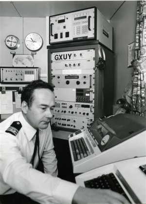
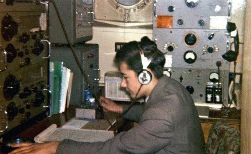
Below shows a very young me in the radio room of the North Sea collier Wandsworth, in 1962.
The older picture was taken 20 years later in the radio office of the passenger liner RMS St Helena, when valves were a thing of the past. I went from colliers to some of the finest passenger liners is the world over a career of 31 years. Final picture, the old RMS Windsor Castle, in which, I served for about 5 years, as 4th, 3rd and finally 2nd radio officer. 38,000 tons, 250 first class passenger and 600 tourist class. The SS United States was still sailing at that time.
We have strayed off topic somewhat, but I hope you have found the digression interesting.


Windsor Castle 1 leaving Southampton.JPG

Bob Wilson  RMS St Helena 1983.JPGI was 17.


Me in radio office - Copy.JPG

V2 V3 wiring (Large).JPG


3 Valve TRF (Large).JPG
 
We have strayed off topic somewhat, but I hope you have found the digression interesting.

Absolutely interesting and had me waxing nostalgic.

Back in my junior year of HS, you know - when there were actually "shop" classes and such, I took Electronics as an elective. For several years, the curriculum had included the construction of a 3 or 4 (I can't remember) valve AM radio receiver, similar to the above, but built on a stamped sheet metal chassis. You were given the chassis, the schematic and some pictorial drawings of the parts layouts. All the other components were in bins along the wall. The deal was, if you got your radio working, you got to keep it. All the non-working radios were disassembled over the summer and the parts returned to the bins. Realizing this, I knew that every part had to be tested prior to use - no one else did that.

I was the first in the history of that program to keep my radio. ROTF
That was interesting. I would have loved to be involved with something like that.
 
All the non-working radios were disassembled over the summer and the parts returned to the bins. Realizing this, I knew that every part had to be tested prior to use - no one else did that.

I was the first in the history of that program to keep my radio. ROTF
Ah yes, Thinking outside the obvious challenge to assemble the parts. I recognise that mindset. My own 'subject' being software, it seemed always to be me who queried everything outside the obvious requirement for a new or changed widget.

J
 
Yes, but it looks like it's just there to bias the grid in the audio amplifier tube. Follow the schematic and you'll see that it never makes a complete circuit - it's always blocked by capacitors (which don't pass DC). The power comes in from the far right - one voltage for the tube filaments (LT - 2 volts) and one for power (HT - 90 - 150 volts).
Technically, it is still a "power supply". :)
 
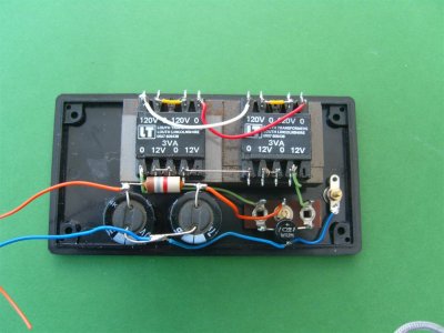
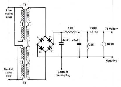
If you want a power supply, here it is - 75 Volts is enough for this radio receiver. I know that four times 12 Volts comes out at 48 Volts. But 75 is available at the output. The LT for the filaments is from a modern 2 Volt sealed lead acid, rechargeable. I altered the value of the
2.2K resistor, and added the 22K bleed resistor later -


1a (Large).JPG75 Volt Circuit with lettering copy (Large).jpg
 
If you want a power supply, here it is - 75 Volts is enough for this radio receiver. I know that four times 12 Volts comes out at 48 Volts. But 75 is available at the output. The LT for the filaments is from a modern 2 Volt sealed lead acid, rechargeable. I altered the value of the
2.2K resistor, and added the 22K bleed resistor later -


View attachment 519998View attachment 519999

That makes perfect sense. Most 12V (nominal) transformers are actually 12.6V RMS (root-mean-square) which is (in layman's terms) kind of an average of the voltage of a sinewave. Peak voltage, however, is the maximum voltage that the sine wave reaches and is what is passed through the bridge rectifier. The four 12.6V transformers in series would put out 50.4V RMS, which comes out to 71.33V Peak.
 
Back
Top