• Ships of Scale has incorportated an extra level of security when you log In. Please follow on-screen prompts to acknowledge that you are not a robot via a "Check Box" or a "Pictorial Check Box Puzzle". This is needed due to higher level of AI Activity Security.
  • SUBSCRIBE TO SHIPS IN SCALE TODAY!

    The beloved Ships in Scale Magazine is back and charting a new course for 2026!
    Discover new skills, new techniques, and new inspirations in every issue.

    NOTE THAT OUR NEXT ISSUE WILL BE July/August 2026
  • Win a Free Custom Engraved Brass Coin!!!
    As a way to introduce our brass coins to the community, we will raffle off a free coin during the month of August. Follow link ABOVE for instructions for entering.

Rattlesnake - a semi-kit Hahn model

Joined
Dec 7, 2022
Messages
211
Points
113

This class-offering certainly will have similarities to Dave Steven’s exposition on Sir Edward Hawke; but it will also have noticeable differences. With respect to hull construction, Dave created laser cut components to build many of the Hawke frames. Here we will stay true to the Hahn method – building sistered frames from strip stock. Full masting and rigging is also planned for this model.

I will be working from the semi-kit that is made available at The Lumberyard for Model Shipwrights. To help guide the construction of the model there are several Harold Hahn documents that I will appeal to. In Dave’s thread on Harold Hahn it was made exceedingly clear that beyond Hahn’s modeling and artistic skills, he also was a prolific author!

Some of the Hahn literature that I find useful for this project include:

Ships of the American Revolution and Their Models. In this book, Hahn provides basic construction information on 6 ships and detailed information on creating a model of HMS Alfred. While Alfred is a much more involved model than that of Rattlesnake, the techniques involved are basically the same.

Rattlesnake, a 20-Gun Privateer. This article was published in the Nautical Research Journal Vol 39 No 1. You can also find a link to the original typed manuscript within Dave’s thread on Harold Hahn. In this article, Hahn talked about choices he made in creating his plans and model. Some pictures of the model were printed in the article. Interestingly, a full set of plans were published as part of the article.

I will also be making use of a collection of photographs of Hahn’s Rattlesnake model that can be viewed at https://www.modelshipbuilder.com/img/models/rattlesnake.pdf

Harold Hahn drew his plans based on drawings made by Howard Chapelle, George F. Cambell (who produced plans for the Model Shipways Rattlesnake kit), a model of Rattlesnake that was held by the Smithsonian, as well as Admiralty drawings.

Chapelle noted that history of Rattlesnake was vague, but that she had received her first commission in June of 1781. In 1782 the ship had been captured by the British and renamed Cormorant. At this time the Admiralty drawings were made. Apparently, the ship was renamed Rattlesnake in 1784. This information was all gleaned from Hahn’s article in the NRG.

It was this photograph of Hahn’s model that hooked me quite a while ago:
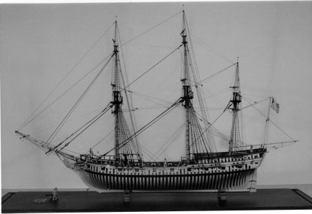
Hahn Rattlesnake Model.jpg

An order was placed in 2017 for the semi-kit. It has been on the shelf for a while and now it is time to get to it. A very interesting aside – The Lumberyard has NOT increased the price of this product; it now cost exactly the same as in 2017!
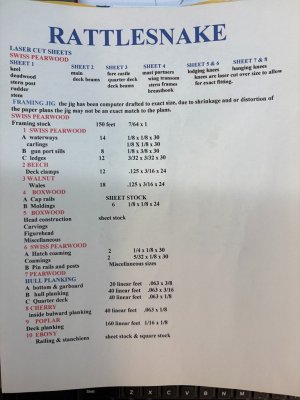
 
Below is a list of what materials are provided in the semi-kit. What makes this a semi-kit, is the inclusion of several sheets of laser cut parts.As you can see, I chose the Swiss Pear timbering set.


Material List.jpg

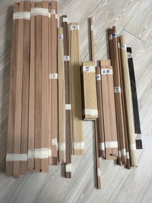
The supplied wood is nicely bundled and identified to match the content list.

1790565822286.jpeg

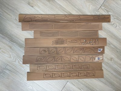
Here are the laser cut sheets:

1790565861637.jpeg

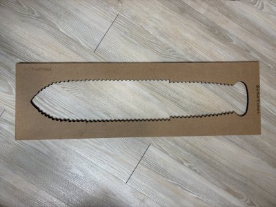
An important part of building in the Harold Hahn method is having an assembly jig to position frames. Such a jig - laser cut - is supplied:

1790565998734.jpeg

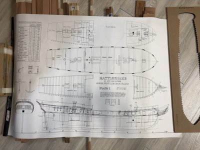
Finally, a full set of plans in the scale of 1:48 (i.e., 1/4" = 1') is included - rolled / no creases. There are 6 sheets in total - including masting and rigging information.

1790566091899.jpeg

What you will not find is an instruction manual. This is where the material referenced in my previous post will quite useful.

In Hahn's descriptions of how he constructs his models, the starting point is typically the assembly jig. Here that is already done. Next he tends to build the stem-keel-stern post - deadwood 'backbone' of the model. This is then followed by fabrication of frames.

So as not to take up anymore bench space than needed initially, I have decided to go straight to fabrication of the frames. How this is to be done will be introduced and/or reviewed in a forthcoming post.
 
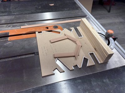
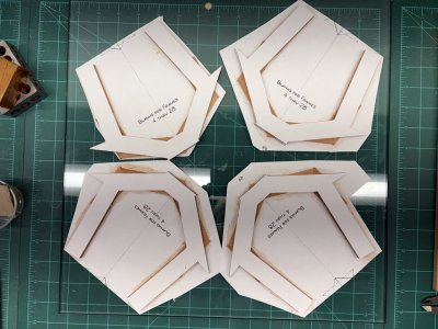
Following Hahn's exposition on Alfred, I constructed a jig to cut pieces needed for the frame blanks associated with frames 4 thru 28.

1790649444647.jpeg

The slots on the left are used for the 'top' layer of the frame blank; those on the left for the 'bottom'. The top extensions are rectangles and require just one cut in the jig (assuming the strip being cut has been cut perpendicular at the end). The other pieces are trapezoidal and need appropriate angles cut on each end. The two top slots on the right side of the jig are for cutting the piece that has the most extreme angle. First the shot slot is used to cut the lower (less extreme) angle. The strip is then inserted in the second slot to cut the piece to its final shape.

The jig itself is based / copied from Hahn's work. A piece of 1/4" Masonite was cut wide enough so the saw blade would reach both edges depending on which slot the miter gauge was positioned in. The Masonite is screwed to the bottom of a piece of pine, that in turn is screwed to the miter gauge. A 140 tooth 7 1/4" hollow ground saw blade was mounted in the table saw. Each side of the Masonite board was then cut. Copies of the frame blank components were made, each cut as needed and rubber cemented to the Masonite. Here it is important to get the edge angle perfectly aligned with the board! Next, using band saw and scroll saw, the slots were cut out. The jig was done. Jigs for other frames will be made later.

The strip framing material that was provided in the Rattlesnake timbering set is 1" wide. From what I can gather, Hahn like to work with stock cut to 7/8" - the plans themselves measure out at about 13/16". So I've set the jig slot with to 7/8" while maintaining the correct length of pieces as well as angles.

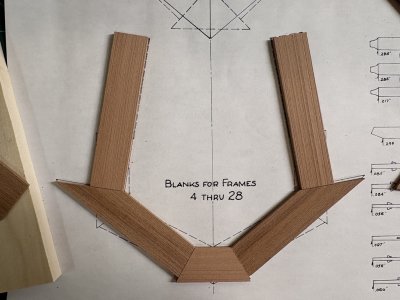
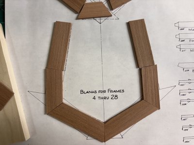
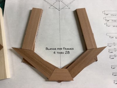
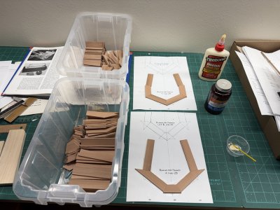
A couple of framing strips were ripped down to 7/8" and the jig was tried out. Below are the resulting pieces laid over the plans. To keep the pieces in each layer from moving around during the glue up, Hahn had rubber cemented the pieces of each layer to a copy of the frame blank plan. The two layers were then set on one another to arrive at the correct overlap position. He then drilled several holes thru the blanks to accept shot pieces of lil pins - these were used to maintain alignment when the layers were glued together. I get why he did that as these trial pieces don't want to stay where I set them!

1790650972126.jpeg


1790650990485.jpeg

1790650952007.jpeg
 
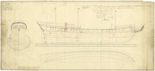
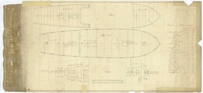
Greg, have you seen the drawings available at Wiki Commons. These are apparently public domain and royalty free.
If you download them, they are huge with very fine detail.

Cormorant ex Rattlesnake

If you click through there are three sheets.
Yes - these are the drafts 6185/50 and 6185A/50 that Hahn refers to in his NRJ article. Thank you for placing the link in this thread!

Greg

Here are what the Admiralty drafts look like:

1790705157367.jpeg

1790705169867.jpeg
 
Greg,

I have a variation of your current method "presented for your consideration".

You will be building this 1/4":1' with all bends and R=S?
It will be upside down - the top timber having an extension to produce a baseline above all of the frames - the keel present from the start and notched for the floor timber and futtock 1?

Do you plan to plank from the wale to the rail or be open framing above the wale?
 
Yes 1/4" = 1', room = space, etc. Completely in the fashion of Hahn - so upside down with all of the extensions to set the keel level. The included laser-cut keel is notched to receive the floor timber and futtock 1.

I have not decided how much of the model will be left open. Besides being a 'School Project' this, I'd promised to build this model for my son - so it will be staying in the family! As the projects progresses, I will be consulting with him with respect to how much planking will be added. There are so many options! Currently, I feel the fashion is to completely plank one side of the model and leave portions of the other side open. That type of presentation certainly looks nice, but I also very much like the look often associated with dockyard models - open below the wales - where you can look straight thru the model.
 
OK lets go:

Use temp Pine in the spaces. It is a more stable hull. The keel can go last and does not need notches.
The hull does not have to live in the jig. The hull can be free in space while it is being faired.

Pine - the 2x4 deals on the aisle at Home Depot - not Fir, not Spruce - white Pine - min knots and no gum.
Make it the same thickness as the framing stock or twice the thickness - except for .......

It can be assembled as a bend the same as the frames : same thickness
or
as one single piece from center line to rail. : twice the thickness

How do I make it temp?
I have three possible ways:
1. - Scotch permanent double sided tape -
it works and I have been using it right up until my current project. On Centurion - ethanol killed the bond and allowed the Pine to be pushed out after it did its job. The problem is that the tape likes the Maple frames more than it likes the Pine. I do not like dealing with removing it from 200+ narrow slots. For Gracie S I applied three coats of super blond shellac to the space faces of the Black Cherry. I figured that the ethanol would solublize the shellac and the tape would come out with the Pine. - Wrong! The tape likes shellac more than Pine. Nine more gaps with ethanol and a single edge Gem blade and Gracie S will be at my stopping point. I have to be careful with the ethanol. The reverse agent for TitebondII is 2-propanol. I do not find much difference in chemical properties between ethanol and 2-propanol so I try to keep the ethanol away from my Cherry to Cherry bonds.

2. Duco
First time that I tried it, use applied it the same as TitebondII. It did not stand up to my shear forces.
I have since read the directions on the the tube: coat both surfaces and let dry. Add another layer of Duco and join the surfaces. It works if I do it this way. Acetone is quick to reverse Duco bonding- TitebondII is not easily affected by acetone. I am using this now.

3. The proper method:
Liquid hide glue with paper wick layer between the two wood surfaces.
Wedding present white tissue paper - very thin - not sure if it is enough of a wick.
NewsNewspaper - there are drawing pads with sheets of cheap lose fiber clear newspaper.

I think newspaper. Mike the thickness of two sheets and add 0.001"-0.002" for the glue and subtract this from the thickness of the sum of the Pine thickness.
Franklin liquid hide glue is too watery for wood to wood for me. It also has zero tac. The open time is longer than TitebondII. Apply as dots - do not completely coat both surfaces if you want reversal of the bond. Near boiling hot ethanol will instantly denature the protein that is hide glue. It curls up into balls.

I think that Hahn omitted the short top timber. Anyway - for my suggestion - this does not matter.

If you chose to plank over the framing from the wale to the rail:
Have a short top timber that is Pear. Plus, instead of the space fill Pine, have two top timbers in the space from the wale to rail that is TitebondII bonded. I would use Yellow Poplar and it would be the exact thickness of the Pear. The deadwood - wood that is the width of the keel and fills the gap between the top of the keel and the bottom of the keelson - Make some Pear deadwood that is as wide as two frame thicknesses and perm bond it. Instead of notching the keel for the frames - a pin or dowel into the new deadwood dies the same job with much less fiddly milling.

Other stuff about the Hahn method:

I thought about the shaping - one pattern on the bend rubber cemented to to the out board face of the bend. You can use the table of your drum sander and get the shape out and in. Then freehand the outside bevel to the pattern. You can then cement a second copy of the pattern to the midline face of the three line shaped bend and freehand the inside bevel.

The space Pine patterns cane be copied from overlaying the two bend patterns and printing them out,

When I framed Kate Cory using the Hahn method I used a stack of old dense solid bricks as a frame press. For Titebond - the closer the two wood faces are, the stronger is the bond. I was not happy with the bricks. I bought a cheap on sale bench pipe clamp from Harbor Freight and with 3/4" plywood and dowels I made a wine press type frame press 58_frame press.jpg

From what I can tell - the HF sale was a clearance sale - I have found no bench top pipe clamps since then that are not absurdly expensive.
I saw this ShopFox (Grizzly) that came with a cast metal cross bar - but now it is just the threaded rod and the piece to anchor in a DIY cross barShopFox press.jpg
I figure with everbilt-angles-800117-64_1000.jpgand some bracing and 3/4" ply a right powerful frame press can be assembled.

For a a bend, I would probably use this HF 4" ratcheting bar clamp from HF - before inflation and on sale they were <$2 BUT only this specific model - the one with the large grey twist screw. clamp 4inch.jpg And as many as there is room for.
Every other model - MM - HF small twist - and especially Irwin are from hunger. Weak - no real pressure - some the trigger breaks if you breathe on it,
 
Last edited:
Back
Top