Santa Maria 1:65 based on Amati kit

Joined
May 1, 2023
Messages
115
Points
113

Hello everyone,

I wanted to share my progress on the Santa Maria 1:65 ship model that I've been building for a few months now.
Initially, I started with an Amati kit, thinking it would be an "easytobuild" straightforward project lasting only a couple of months. However, after obtaining books by X. Pastor and W. zu Mondfeld, I decided to deviate from the kit instructions. Now, it's hard to determine if I'm building from a kit as many details and elements are designed absolutely from scratch by myself.

The more I diverge from the instructions, the more fascinating the process becomes.

I would like to share my journey with all of you.
However, considering that the ship is already approximately 30% built, I don't think it would make sense to start this log from the very beginning.
Instead, I believe it would be more practical to begin from the current stage.

What are your thoughts on this?

Here is the current stage of the model as of June 09, 2023 (construction is still ongoing).
MVV_5773.jpg

Please scroll down for actual building log posts.
 
Last edited:
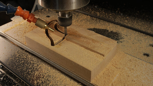
Personally speaking - I would eagerly follow your build from this point. Your work on that CNC transom adds a dimension beyond my skill set so that has now gotten my attention.
Dear Paul,
Thank you. Yes, now, at least at this stage of the process, I see more and more necessary in CNC machining of some parts. I work on the admiral's cabin now where I have to precisely join many details with special corners (none are 90° ☺). So I do not know what would I do without a CNC :)
 
After reading your excellent threads on the windlass and capstan you CNC-machined, as well as your CNC composite machining (both truly amazing), how could I NOT follow this thread. Kudos on your videos, as well; I have a new Youtube channel! :-)
 
Dear everyone, thank you for your kind words!

Let's get started.

When it comes to each iteration, at least in this project, I begin in the same way. I go through available sources repeatedly. First, I look through them in a general sense, and each subsequent time, I focus more on a specific area of the ship or detail. This process stirs in my mind and eventually results in a vision. To capture this vision, I try to document it with numerous sketches, like this:

01_Sketches.jpg

At this stage, I have two issues to share and discuss with you.

  1. After looking through the sources, deciding what and how I'll create, and even after completing a particular task, I often find myself stumbling upon new sources and alternative methods to accomplish what I've already done. This constant pursuit of perfectionism needs to be controlled at some point. Have you faced a similar situation? How do you deal with it?
  2. Throughout the years, I have been sketching, whether as a photographer or a ship modelist. However, I've never been able to maintain a dedicated sketchbook, despite purchasing several. I always end up drawing on separate sheets. What is your practice when it comes to this?


    I remain working on new posts to this thread and the model itself,
    Rgds,
    Max
 
This constant pursuit of perfectionism needs to be controlled at some point. Have you faced a similar situation? How do you deal with it?
Interesting topic. I also run in the direction of perfectionism. And in many ways I believe this is a good thing - a high level of achievement (I think) is to be admired. And then there is the saying: perfect is the enemy of good. There is truth here as well. I have spent unknown hours working and reworking something that turns out only marginally better and in almost every case the 'normal' person (translation: healthy person ROTF) can hardly see the difference.

My remedy? Time has become increasingly valuable to me so when something starts to take 'too long' then I quite willingly abandon my pursuit and settle for good. Or in the specific case of model-making I have found that the materials we use (or the scale we work in) cannot sustain the measure of perfection, so I allow that to control my tendencies. Or when it just stops being fun...
 
Why not to show only some of the main working steps from the beginning, only to catch up the status and than full of energy from the actual status
BTW: Very interesting CNC work you showed already ..... I am looking forward
 
Why not to show only some of the main working steps from the beginning, only to catch up the status and than full of energy from the actual status
BTW: Very interesting CNC work you showed already ..... I am looking forward
Uwe, maybe you are right.
The log will not look complete if started not from the beginning. So after some fight with my laziness, I decided to start from the start.

1. Amati Kits
I like Amati kits because they provide the freedom to create. The modeler can use parts and instructions from the kit, which significantly reduces the time spent on assembly. However, if one wants to be more creative and has the tools, knowledge, materials, and passion for it, the sky is the limit. The only question in this situation is why wouldn't Amati make special kits for that purpose - just planks and drawings, while the rest could be optional.

So, even before purchasing a kit, I knew that I would replace some parts. But initially, I only planned to make small adaptations.

2. Skeleton dry assembly and conclusions made
After I had just dry-assembled the skeleton I saw two main things:
1. The plywood edge of the keel would be visible on the finished model, and the instruction manual does not offer an organic way to hide it.
2. The bulkheads would require additional fixation to maintain a 90° angle between them and the keel.

Additionally, from the very beginning, I wanted to light the model from the inside. So the dry assembly gave me some ideas on how to conduct wires.
Although I followed these ideas, they appeared irrelevant and eventually, I conducted wires in a different way:)

MVV_3438.jpg


3. New keel
The first thing I wanted to change was the keel. Therefore, I designed the visible parts of the keel in Fusion 360 and cut them out. This was an initial version, and I planned to make some slight improvements later on.

Since the final planking offered by Amati resembled walnut, I decided to create a walnut keel to match.

Additionally, I had to make necessary modifications to the kit's plywood skeleton keel. This involved cutting out areas for the walnut parts to fit in and creating pockets for future metallic rods, which would serve as the stand fixture.

MVV_3456.jpg

Here is the initial version of my substitute walnut keel.

MVV_3526.jpg


4. Strengthening the skeleton
To eliminate wobbling and ensure straight angles between the keel and bulkheads, I decided to incorporate inserts. However, due to my laziness, I only created 3D inserts for the first four spaces between the bulkheads from the stem and the last four from the stern side. For the remaining spaces, I opted to cut precise rectangular bars measuring 4 mm in thickness.

In hindsight, if I were to do it now, I would likely fill in all the spaces with 3D bulkheads. Although it requires more time to make them, the resulting hull would be much more rigid, making the planking process easier. Additionally, there would be no limitations when it comes to attaching anything from the outside to a hull constructed in this manner. The walls would be thick and rigid enough to securely accommodate nails, screws, and other fasteners.

Here are F360 models of some of the 3D inserts.

2023-06-18_161638.jpg

MVV_3534.jpg


5. Final set of details and finished skeleton
Once I finished cutting everything I needed, I ended up with this set of components.
(The round holes in the bulkheads were initially intended for wiring the lighting. However, later I decided against wiring through them as it would have been too complicated during the assembly process.)

MVV_3591.jpg

After the assembly, followed by some sanding, puttying, and additional sanding,
the skeleton began to take shape and looked like this.
MVV_3649.jpg

01_.jpg
 
Last edited:
6. Planking
The model is designed to have two layers of planking.

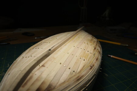
The first layer of planking was relatively straightforward. Given my confidence in the quality of the surface I had prepared in the previous stage, I decided to experiment with different planking techniques. On one side, I attempted to apply the planks in a more traditional "correct" manner, using trimming and shaping techniques. Although I invested considerable time in achieving a visually pleasing result, the overall "beauty" of the planks and their layout fell short of perfection.

On the other side, I took a simpler approach. I applied the planks following the natural shape of the wood and then filled the gaps between them with specially trimmed pieces. At one point, I regretted not having made 3D inserts between all the bulkheads, but fortunately, this did not cause any significant issues. Eventually, I managed to lay the planks as I intended.

The most important aspect was the resulting surface quality, which left me completely satisfied. Both sides of the model exhibited a high degree of symmetry, as far as I could observe and measure.

Here is the outcome of the first layer of planking Before sanding).

MVV_3880.JPG

MVV_3884.JPG

And here is what I have achieved after applying putty and sanding the surface.

MVV_4066.JPG

MVV_4069.JPGMVV_4064.JPG


The second layer of planking, being fully visible, required meticulous preparation to ensure absolute symmetry and accuracy. To achieve this, I followed a different approach from the simplistic recommendation of Amati. Instead of applying all the final planks first and then adding the wales, which can create more problems than simplicity, I opted for the classical method.
The hull of the ship features several parallel wales, which provided a natural division of the hull surface into three belts situated between the wales. Each belt represented a slightly different approach to planking. By employing this division, the planking strategy within each belt became much clearer and more manageable.

To start the planking process, I took the necessary time to mark the bulkhead projections on the hull. Instead of applying full-length 40 cm planks or using planks that span only two bulkheads as recommended by Amati, I decided to adopt a more traditional approach for calculating plank length.

Following this approach, I determined that the ideal plank length would be four times the distance between bulkheads. In order to create the bulkhead projections accurately, I even designed a specialized device. Although it worked reasonably well, there is room for improvement, and I may refine it in the future. I am always open to ideas and suggestions, so please feel free to share any thoughts you may have.

Here is a picture of the device on its own and in action.

Dev.jpg

Dev2.jpg

After creating the bulkhead projections, I proceeded to create a layout map. Although not strictly necessary for a body like this, it helped me gain a better understanding of the future layout of the planks.

Additionally, I calculated and marked the width of planks on each bulkhead projection. This served as an essential guide to ensure the symmetry of the planking on both sides of the hull.

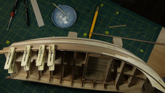
With all the preparations complete, I dedicated time to carefully position the wales in their correct locations and securely glued them in place. This crucial step established the foundation for the subsequent planking process.

This is how wales looked at that stage.
Looking at the picture now, I can see that I would have lifted the stem part of the second wale.
However, at the time when I did it, it appeared to be in the correct position to me.

MVV_4160.JPG


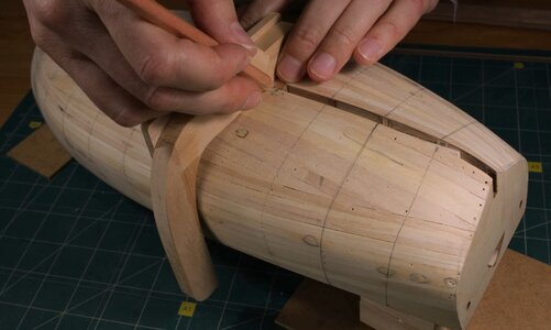
I began the planking process by working on the two upper belts. There is nothing particularly noteworthy to mention about this step, as I only had to slightly shape some of the planks to fit the curvature of the hull. The shaping process was quite straightforward: I used a straight ruler and cut the planks at the required angles until their width matched the markings on the hull surface. Again, only some planks were required to be shaped within those two belts.


MVV_4271.JPGMVV_4248.JPGMVV_4286.JPG


The lowest belt of planking posed the most challenges due to the curvature of the hull. My primary goal was to avoid having any drop planks, which can be difficult to achieve symmetrically at this scale. To accomplish this, I took great care in shaping the planks correctly and bending them in two planes.

Bending the 0.5 mm planks along their length was not too difficult, but bending them perpendicular to their axis proved to be quite a task. To aid in this process, I created a bending device specifically designed for this purpose. It allowed me to achieve the desired curvature without compromising the symmetry of the planks.

If you would like to see how the bending device looks and works, I have a short video demonstrating its usage.

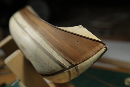
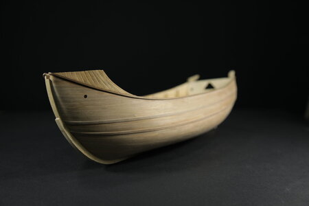
Additionally, I made the decision to recreate a clinker planking for the forecastle area, as demonstrated in Xavier Pastor's book.
This choice, I think, would add an extra level of authenticity and uniqueness to the model.

The only thing to note here is that I believe the planks should overlap in the opposite direction to what is shown in the picture below.
The overlapping pattern should resemble the direction of roof tiles on traditional roofs, as they are designed to prevent water from seeping under the roof.


Clinker.jpg


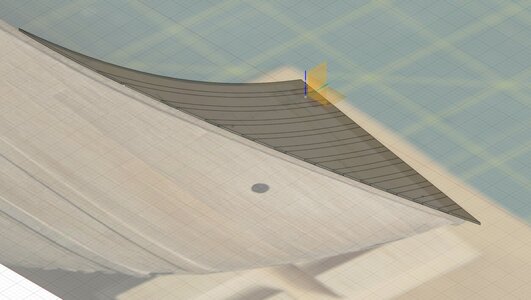
To recreate the clinker planking, I began by sketching the design and layout of each individual plank. Using Fusion 360, I then modeled each plank according to the desired dimensions, allowing for plank thicknesses between 0.25 mm and 0.5 mm.


Clinker3.jpgClinker2.jpg

Among the wood options available to me, I found that pearwood was the most suitable for this task.
It not only proved to be resilient enough to withstand the cutting process, but also maintained its visual appeal afterwards.

Finally, I came to this:
MVV_4453.JPG


IntermStage_View.jpg
 
Last edited:
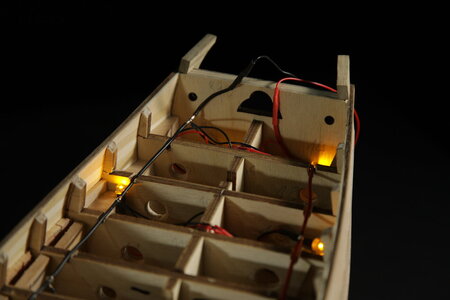
7. Wiring and lights.
After completing the planking, it was time to work on the wiring for the lights.
Even before purchasing the "Santa Maria", I had the idea of incorporating lighting into.
I had even created a lower-hold compartment to house a couple of light sources.
Although I would approach it differently now, I am still satisfied with how it looks.

For the power connection, I decided to try a special approach.
Instead of the common method of adding a "third" leg on the model stand with contact wires inside, I opted to use just two legs.
Since these legs already contained a metal rod, I thought, why not utilize them as electric current conductors?

Now, having completed all the lighting work (which I will share in future posts), I can confidently say that this was the right strategy.

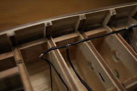
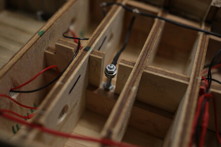
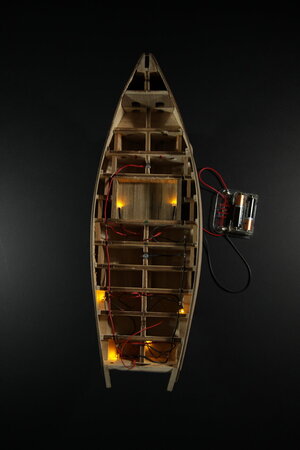
Additionally, as I examined the finished hull, it became apparent that the holes I had previously made in the bulkheads were not suitable for conveniently running the wires. To address this, I simply cut pockets from the top of the bulkheads to accommodate the wires.

That is how I plugged the wires in:

Electric_Scheme.jpg

Here is the result after connecting and placing all the main wires inside the hull:
MVV_4577.JPGMVV_4563.JPGMVV_4584.JPGMVV_4582.JPG

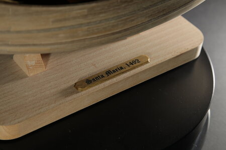
I also created a temporary stand for the model and experimented with a model nameplate, allowing myself to gather some inspiration for future designs.

MVV_4490.JPG
MVV_4543.JPG


8. Deck planking & Co

Now it's time to focus on the deck, internal bulwark planning, and top timbers.
The process was fairly straightforward. I began by installing a central plank and then proceeded to place the remaining planks symmetrically.
I've just cut the planks according to the deck curvature, with no complicated plank layouts. Kept it simple. Also, I did not darken plank edges (neither with pencil nor with thread or other traditional ways).

Again, I decided to be very simple there.
Instead of darkening the plank edges with a pencil or thread, I opted for a diluted brown oil paint to lightly darken the almost white deck wood.
The paint seeping into the plank joins created darker and well-defined lines, achieving the desired deck-planking appearance.

Here are my "secret weapons" for a good deck outlook;) :

  1. I repeated the tinting procedure 3-4 times, wiping off the excess paint with a napkin and allowing the surface to dry each time.
  2. After tinting, I covered the deck with linseed oil. Once it absorbed sufficiently (usually the next day), I sanded the deck with 1000-grit sandpaper and after that once more repeated the process with 2000-grit sandpaper.
The result is a "semi-glossy", soft, and warm-to-touch deck with distinct planking and nailing structure.

You can see the end result in the pictures below and watch the corresponding video on my channel (linked here).

MVV_4679.JPG

MVV_4654.JPG

Highlighted by own LEDs:
MVV_4683.JPG

Then I installed top timbers, waterways and applied finishing planking in between.
It was nothing significant in the area of the waist.
MVV_4810.JPG


However, I had to behave differently in the quarterdeck area.

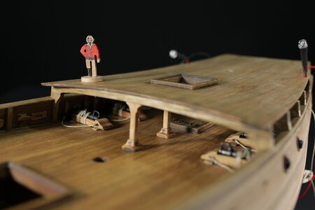
According to Amati's instructions, all the decks are flat, which doesn't accurately reflect reality. Therefore, I decided to deviate from this and aim for a more realistic representation. I wanted to introduce curved beams under the quarterdeck, which meant I needed suitable top timbers to support them.

Additionally, I noticed that the height of the quarterdeck above the waist, as suggested by Amati, was unacceptably low. To address this, I raised the height by at least 4 mm for a more accurate portrayal.

Furthermore, I had to address the challenge of concealing the wires inside the rear top timbers. This posed a potential issue as it could compromise their rigidity. I had to find a solution to ensure both the functionality and appearance of the top timbers.

I came to this shape of supports under the quarterdeck. It's a kind of hybrid of top timber and knee... :)
Sorry for the red color :)

2023-03-31_185133.jpg

After installing all these components in their respective positions, I achieved the following result:

3.jpg


9. Guns

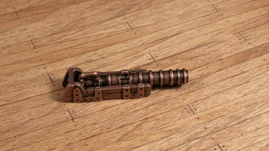
Guns... They have been the first candidate for replacement. Upon initial inspection, I was dissatisfied with their color, precision, and metallic carriages.

Here's how the gun looked straight out of the box:
Gun_Kit.jpg


I thought I would at least put barrels on my lathe.
At first, I considered putting the gun barrels on my lathe for some modifications. However, after careful consideration, I decided to keep the barrels as they were with just a few adjustments:
  1. I drilled the cannon bores to a depth of at least 8-10mm. Initially, they were only 1-1.5mm deep!
  2. I cleaned the barrels, removing the strange "brownish" and "copperish" color, revealing the white alloy underneath. Then, I blackened them using Brass Black.
As for the metallic carriages, I decided to completely replace them. I proceeded to cut wooden carriages as replacements.
The idea was to be closer to lombard cannons of this type:

Gun.jpg


However, since these guns would eventually be hidden under the quarterdeck, I didn't see the need to invest too much time in their modifications.
Here is the comparative result of my experiments:

Banner.jpg


10. Forecastle

Having in mind some deeper modifications of that area, I decided to refuse of using the forecastle base, proposed by the kit.

Furthermore, I realized that the "tilla" (the space under the forecastle) should not look the way Amati proposed. Unfortunately, it was already too late to correct this as I had not yet received my books about the Santa Maria, which would have provided the necessary information.

In hindsight, the wall of the "tilla" should not exist at all, and this is something that should have been addressed from the very beginning.

This is what we have in available reconstructions (X. Pastor's book):

Tilla_1.jpg


Tilla2.jpg

And here is what Amati designed:

Tilla-3.jpg

After considering of modifications possible in this situation, I came to this mockup:

MVV_4957-.jpg

I initially created a cardboard version to quickly assess its fit. Additionally, I decided to conduct a small experiment. The planks you see in the above picture were all cut by myself from a piece of pearwood. I did not use any planks from the kit for this detail.

For the first time in this model, I chose to use the "pre-glued" method for planking. This involved gluing the planks together before cutting the detail.

And this is how the detail looks after cutting. Correct centering on the CNC table gave me almost perfect symmetry of planks.

MVV_4964.JPG

The assembled Forecastle looks like this:
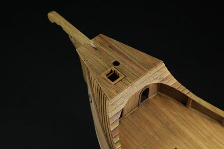
MVV_5048.JPG
 
Last edited:
11. Windlass

I tried to replicate this windlass:
Tilla2.jpg

The result is described in my CNS post here:

Here are some on-deck elements, although not all of them will be used in the final build.
E.g. one element that I plan to revamp is the capstan, aka the vertical windlass. According to Xavier Pastor's research, these capstans could be portable and used both on board and ashore. If I feel inspired, I might create a portable capstan later on. Anyway, it will remain unglued as it is meant to be movable.

The red figure, whom I affectionately named "The Man of Scale," was created to assist me in maintaining accurate proportions throughout the build ;)


MVV_5342.JPG

12. Quarterdeck zone

Before proceeding further, I took the necessary steps to prepare the quarterdeck.
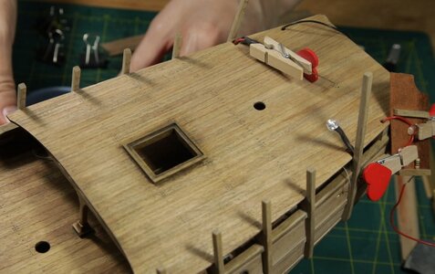
Given the quarterdeck's large surface area, I wanted to ensure that it had the necessary rigidity to prevent flexing. Therefore, after installing all the components I wanted to include under the quarterdeck, such as guns, cleats, sheaves, and rope coils, I began working on the beams.

I designed them in Fusion 360 and cut them out with CNC from walnut.

Beams.jpg


MVV_5470.JPG

Once the beams were in place, I realized the importance of providing additional support to enhance their stability.
This was particularly crucial for the beam closest to the stern, as it housed wires within it. To address this, I inserted wooden bars between the beams and installed two vertical columns to provide additional reinforcement.
These measures ensured that the beams were well-supported both vertically and horizontally.

Here is the hull, almost ready for quarterdeck installation (columns are not yet installed):

MVV_5523.JPG

After a satisfactory result with Forecastle, I decided to make the quarterdeck using the same approach. First, I glued planks to the veneer, then - cut the deck detail on CNC.


5.jpg

QDeck model.jpg

And here is the deck already installed:
MVV_5572.JPG

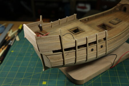
Here is how the ship appeared after the quarterdeck had been installed:

MVV_5588.JPG

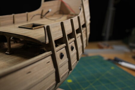
I proceeded to work on the futtock riders and side panels, which were formed by the quarterdeck bulwarks and the sidewalls of the admirals cabin.
Due to the modifications I made to the quarterdeck design, the dimensions of the side panels needed to be adjusted accordingly.

To create the side panels, I used Fusion360 to design a veneer base, which was then manufactured using my CNC.
Once the veneer base was ready, I carefully planked it from both sides to achieve the desired look and finish.

Side pan.jpg


But I had to design and install futtock riders first.

FR1.jpg
FR2.jpg

And this is how installed side panels look:
MVV_5694.JPG
MVV_5687.JPG


And with that, I bring this brief recap of my Santa Maria building journey to a close.
Don't worry, though! I hope to keep you updated with my real-time building adventures from now on.
So, brace yourselves for more exciting updates!

A big shoutout and thank you to all the brave souls who ventured through this lengthy read.
I truly appreciate your time and dedication.

Now, stay tuned and prepare for the next chapter in this shipbuilding saga.
Maybe it's going to be a wild and riveting ride, who knowsROTFROTFROTF!
 
13. The Admiral's Cabin
As you may know, Amati's design of the Admiral's Cabin is quite simple. They propose using just planking and false doors on the front wall, and planking with two windows on the back wall. This is acceptable. Actually, their simplicity could be somewhat realistic to a certain extent. However, it's a bit boring for me, especially after seeing other reconstructions.
Therefore, I have decided to experiment with embellishments a bit.
If you're interested in how I arrived at the construction and design of the cabin walls, you can read about it in my trhead on CNC machining of composite materials.

But even before installing the walls, I had to consider hiding wires.
So I had the idea of using false panels in mind. I cut these panels from cherry veneer, which has a very interesting color. It is too saturated for the exterior but perfect for the interior. And here is how those panels look:

04.jpg

03.jpg

When the walls and side panels were ready, I proceeded to work on some other components.
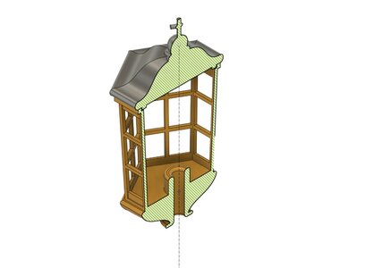
For example, I revamped a stern lantern. I designed it in Fusion360 and 3D printed it. After that, I applied some painting to give it an aged bronze texture.

05.jpg

06.jpg

MVV_5843.JPG

I cut the glass as a single element, creating fold lines without cutting all the way through.
When the dimensions are accurately calculated, this method greatly simplifies the assembly of a small and delicate plastic stern lantern.
The spokes used to construct the lantern have a thickness of only 0.5 mm. So, the glass itself serves as an important strengthening element for the entire structure.

MVV_5855.JPG
MVV_5850.JPG

The same way I cut the glass for the windows in the walls.
MVV_5868.JPG
 
13. The Admiral's Cabin (continued)

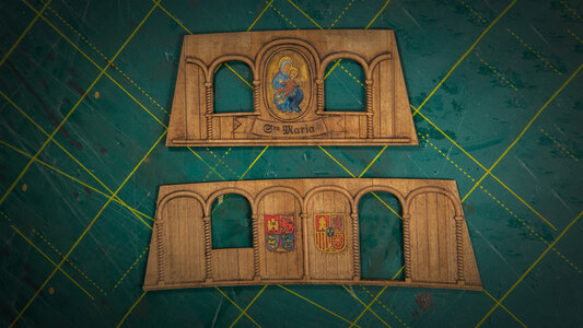
Now I needed to add some color to the nearly white pear wood walls.
Since I planned to incorporate colored elements like shields and St. Maria, it was more convenient to paint these walls before attaching them to the model.

I utilized water-based acrylic paints and a small brush. Ideally, I would have preferred a smaller brush, but just before starting, I realized that the smallest brush I had was a #2. Hence, I proceeded with that one. It did result in some minor imperfections, but overall, everything went well. In addition, I applied brown oil paint over bright acrylic colors to reduce the saturation of reds and yellows, creating an "aged" effect for those colors. This was a deliberate choice, as the brown paint effectively emphasized the edges of the small relief elements and concealed most of the imperfections in the acrylic layers.

In the end, I must say that I am satisfied with the outcome.

The process:
01.jpg


02.jpg


The result:
Pannels.jpg
 
Back
Top