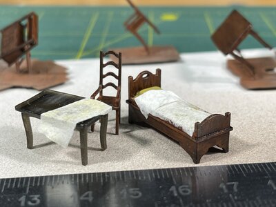
Beautiful micro-painting work. Chapeau mon ami.
-

Win a Free Custom Engraved Brass Coin!!!
As a way to introduce our brass coins to the community, we will raffle off a free coin during the month of August. Follow link ABOVE for instructions for entering.
-

PRE-ORDER SHIPS IN SCALE TODAY!
The beloved Ships in Scale Magazine is back and charting a new course for 2026!
Discover new skills, new techniques, and new inspirations in every issue.
NOTE THAT OUR FIRST ISSUE WILL BE JAN/FEB 2026
You are using an out of date browser. It may not display this or other websites correctly.
You should upgrade or use an alternative browser.
You should upgrade or use an alternative browser.
Santa Maria 1:65 based on Amati kit
- Thread starter ShipmodelIdeas
- Start date
- Watchers 15
-
- Tags
- amati santa maria
- Joined
- May 1, 2023
- Messages
- 115
- Points
- 113

Merci beaucoup !
(Bien sûr, je parle à peine français, mais la technologie moderne peut tout faire !)

(Bien sûr, je parle à peine français, mais la technologie moderne peut tout faire !)
Pulling up a chair, new follower here.Uwe, maybe you are right.
The log will not look complete if started not from the beginning. So after some fight with my laziness, I decided to start from the start.
1. Amati Kits
I like Amati kits because they provide the freedom to create. The modeler can use parts and instructions from the kit, which significantly reduces the time spent on assembly. However, if one wants to be more creative and has the tools, knowledge, materials, and passion for it, the sky is the limit. The only question in this situation is why wouldn't Amati make special kits for that purpose - just planks and drawings, while the rest could be optional.
So, even before purchasing a kit, I knew that I would replace some parts. But initially, I only planned to make small adaptations.
2. Skeleton dry assembly and conclusions made
After I had just dry-assembled the skeleton I saw two main things:
1. The plywood edge of the keel would be visible on the finished model, and the instruction manual does not offer an organic way to hide it.
2. The bulkheads would require additional fixation to maintain a 90° angle between them and the keel.
Additionally, from the very beginning, I wanted to light the model from the inside. So the dry assembly gave me some ideas on how to conduct wires.
Although I followed these ideas, they appeared irrelevant and eventually, I conducted wires in a different way
View attachment 380134
3. New keel
The first thing I wanted to change was the keel. Therefore, I designed the visible parts of the keel in Fusion 360 and cut them out. This was an initial version, and I planned to make some slight improvements later on.
Since the final planking offered by Amati resembled walnut, I decided to create a walnut keel to match.
Additionally, I had to make necessary modifications to the kit's plywood skeleton keel. This involved cutting out areas for the walnut parts to fit in and creating pockets for future metallic rods, which would serve as the stand fixture.
View attachment 380135
Here is the initial version of my substitute walnut keel.
View attachment 380136
4. Strengthening the skeleton
To eliminate wobbling and ensure straight angles between the keel and bulkheads, I decided to incorporate inserts. However, due to my laziness, I only created 3D inserts for the first four spaces between the bulkheads from the stem and the last four from the stern side. For the remaining spaces, I opted to cut precise rectangular bars measuring 4 mm in thickness.
In hindsight, if I were to do it now, I would likely fill in all the spaces with 3D bulkheads. Although it requires more time to make them, the resulting hull would be much more rigid, making the planking process easier. Additionally, there would be no limitations when it comes to attaching anything from the outside to a hull constructed in this manner. The walls would be thick and rigid enough to securely accommodate nails, screws, and other fasteners.
Here are F360 models of some of the 3D inserts.
View attachment 380138
View attachment 380137
5. Final set of details and finished skeleton
Once I finished cutting everything I needed, I ended up with this set of components.
(The round holes in the bulkheads were initially intended for wiring the lighting. However, later I decided against wiring through them as it would have been too complicated during the assembly process.)
View attachment 380139
After the assembly, followed by some sanding, puttying, and additional sanding,
the skeleton began to take shape and looked like this.
View attachment 380140
View attachment 380141
Very nicely done, though that is an understatement for your incredible work. I'm so envious, of your modeling, but also your 3D skills (I can draw them, but my son can't seem to make them) in both resin and wood. (BTW, what kind of 3D resin printer to you have?)
I was going to comment on you color painting the wood prior to applying a finish to the wood. I am really love pearwood, having made the Bonhomme Richard in pear, and use oil or similar finish to bring out its rich color and emphasize the fine grain it has. So I thought that if I were you I'd finish the wood first, then do the painting. But then I saw how you apparently used the brown paint wash over all of the wood, painted and unpainted. That certainly makes it match together, which might not have been possible with the pear finished first. Still, I long for the clear pear finish I love so much. Have you experimented with that at all, giving a "new" pear finish before adding any color? I've found that a bit of gray mixed with any color "weathers and ages" it without any topcoat, but of course adding a glaze or thin paint to accent the 3D effect is excellent.
I am not degrading your work or result in any way; it is truly excellent. But I think that the final effect would have been very similar if you had used any light wood, as the finish is on top of the wood, rather than within it, and my love for pear makes me want to see it more. Oh, and I probably mention it because I'm so darn envious of your work.
- Joined
- May 1, 2023
- Messages
- 115
- Points
- 113

You are absolutely right. Applying a brown wash on top of colored elements I wanted to hit two targets: to enhance the 3D effects and to conceal small imperfections resulting from my supposedly "super-precise" micro coloring skills, particularly in the corners where a thicker wash is accumulated.....but of course adding a glaze or thin paint to accent the 3D effect is excellent.
If I were to first tint the pear and then paint the shields with colored paints, the 3D effect would likely be maintained, but my imprecise brush strokes would become more noticeable.
Regarding adding gray to the paints - totally agree with you. I have the same "aged-looking" results.
And, yeah, I love pear wood too!
Regarding the printer - I use Anycubic Photon Mono 4K (one of the most inexpensive, yet I love the quality) and black eco-resin by the same Anycubic.
Last edited:
- Joined
- May 1, 2023
- Messages
- 115
- Points
- 113

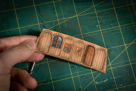
After painting the details, I started assembling the walls step by step.
I installed a window frame with pre-glued glass.
This glass is transparent, as I plan to add furniture to the cabin and hope it will be visible through the window and door.
I decided to make the door openable to add more "texture" to the model and enable even more observation of the cabin's interior. I used black paper strips for the door hinges. The door was also cut with CNC. The door handle is made of 0.3mm diameter brass wire.
Finally, I glued a beam to the back side of the front wall. This beam will support the poop deck and also serve as a stiffener for the wall itself.
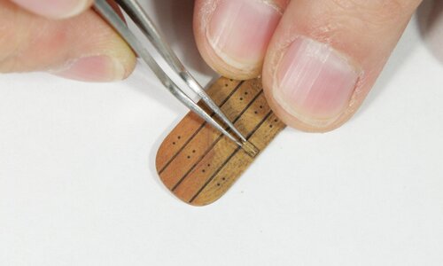

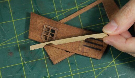
Here is how the assembled front wall looks:
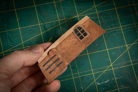
(the window is not black - it's just a reflection)
I installed a window frame with pre-glued glass.
This glass is transparent, as I plan to add furniture to the cabin and hope it will be visible through the window and door.
I decided to make the door openable to add more "texture" to the model and enable even more observation of the cabin's interior. I used black paper strips for the door hinges. The door was also cut with CNC. The door handle is made of 0.3mm diameter brass wire.
Finally, I glued a beam to the back side of the front wall. This beam will support the poop deck and also serve as a stiffener for the wall itself.


Here is how the assembled front wall looks:

(the window is not black - it's just a reflection)

- Joined
- May 1, 2023
- Messages
- 115
- Points
- 113

Hi everyone,
Here is the video on my channel showing some stages of the Admiral’s cabin assembly.
I work further and soon hope to share more progress there.
# 18. Admiral's Cabin | Columbus Santa Maria. Scale 1/65
Here is the video on my channel showing some stages of the Admiral’s cabin assembly.
I work further and soon hope to share more progress there.
# 18. Admiral's Cabin | Columbus Santa Maria. Scale 1/65
- Joined
- May 1, 2023
- Messages
- 115
- Points
- 113

- Joined
- May 1, 2023
- Messages
- 115
- Points
- 113

That's how I did assemble the Admiral's Cabin and put the furniture in...
- Joined
- May 1, 2023
- Messages
- 115
- Points
- 113

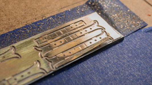
For some reason, crafting the rudders always presents me with certain difficulties. This time, I was hoping everything would go smoothly. The Amati's rudder pintles and gudgeons seemed to be the only parts I wanted to use from the entire kit  . These details are quite accurate. However, upon attempting to assemble them, it became clear that they are much larger than they should be in scale.
Consequently, I had to make some cuts, something I had hoped to avoid at least this time... Naturally, I first had to design the parts in Fusion 360. Unfortunately, it only worked out on the third attempt. During the first two attempts, I miscalculated the measurements, and the pieces didn't fit as expected.
For pintles and reinforcements, I used 0.4 mm thick brass.
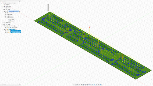
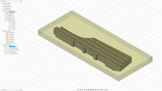
Overall, for now, it seems like everything is coming together nicely.
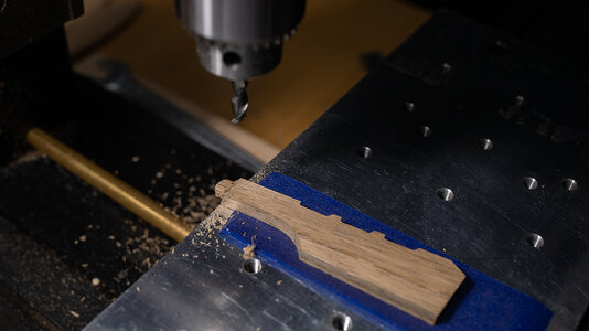
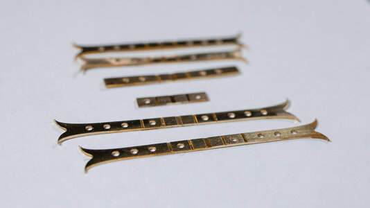
Well, I'm well aware that the solder joints don't look very good at the moment. It might not be the best construction, but it's relatively easy to make. Moreover, it's rather precise (though that may not be very noticeable from the picture). As for the joins, they will be barely visible after blackening (or painting).
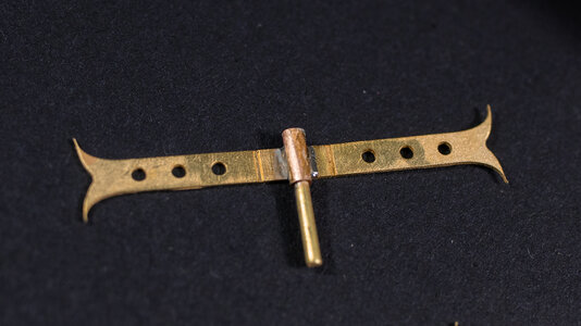
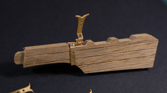
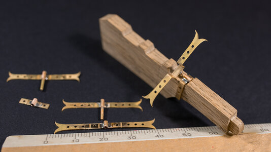
Yet, another challenge awaits me - the solder I used to join the parts isn't blackening with Brass Black. Consequently, if I blacken them, there will be shiny spots on the solder. It looks like I'll have to paint these parts.
Nevertheless, I'll leave that for the future.
Consequently, I had to make some cuts, something I had hoped to avoid at least this time... Naturally, I first had to design the parts in Fusion 360. Unfortunately, it only worked out on the third attempt. During the first two attempts, I miscalculated the measurements, and the pieces didn't fit as expected.
For pintles and reinforcements, I used 0.4 mm thick brass.


Overall, for now, it seems like everything is coming together nicely.


Well, I'm well aware that the solder joints don't look very good at the moment. It might not be the best construction, but it's relatively easy to make. Moreover, it's rather precise (though that may not be very noticeable from the picture). As for the joins, they will be barely visible after blackening (or painting).


Yet, another challenge awaits me - the solder I used to join the parts isn't blackening with Brass Black. Consequently, if I blacken them, there will be shiny spots on the solder. It looks like I'll have to paint these parts.
Nevertheless, I'll leave that for the future.
Last edited:
Jax makes JAX Pewter Black that works on most solder, as well as brass and several other metals.Yet, another challenge awaits me - the solder I used to join the parts isn't blackening with Brass Black. Consequently, if I blacken them, there will be shiny spots on the solder. It looks like I'll have to paint these parts.
- Joined
- May 1, 2023
- Messages
- 115
- Points
- 113

Thank you! I will check it for futureJax makes JAX Pewter Black that works on most solder, as well as brass and several other metals.
- Joined
- May 1, 2023
- Messages
- 115
- Points
- 113

Well, this time I decided to experiment with painting brass details. I've never done it before for the rudder elements; I usually blackened them with Brass Black or similar chemicals. However, this time, I wanted to recreate some kind of old, rusty metal relief. I thought it should work if I applied paint strokes over the airbrushed surface. And, to my delight, it worked almost perfectly.
Of course, the drawback of this approach is that usual water-based acrylic paint tends to peel off metal easily. So I had to deal with that issue - I touched it up with a small brush. In the end, I am satisfied with the result. But for the next time, I would still prefer chemical blackening over painting this way.


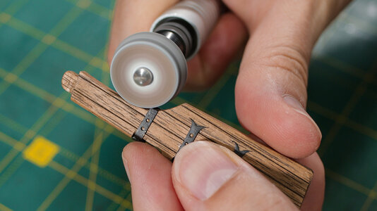
Here, both the "rusty relief" and CA glue are visible. While the "rusty relief" is something I intended to achieve, the latter is an unintended and unpleasant effect. However, there is some good news. Firstly, the glue residue is only clearly visible under magnification and bright light. Secondly, I can effectively reduce its appearance by applying a layer or two of diluted matte paint (either water-based acrylic or oil). This will be done closer to the final stage of the building process.
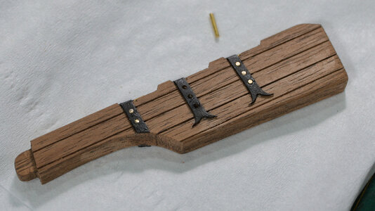
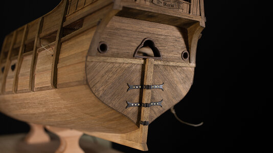

Of course, the drawback of this approach is that usual water-based acrylic paint tends to peel off metal easily. So I had to deal with that issue - I touched it up with a small brush. In the end, I am satisfied with the result. But for the next time, I would still prefer chemical blackening over painting this way.


Here, both the "rusty relief" and CA glue are visible. While the "rusty relief" is something I intended to achieve, the latter is an unintended and unpleasant effect. However, there is some good news. Firstly, the glue residue is only clearly visible under magnification and bright light. Secondly, I can effectively reduce its appearance by applying a layer or two of diluted matte paint (either water-based acrylic or oil). This will be done closer to the final stage of the building process.


- Joined
- Oct 11, 2021
- Messages
- 740
- Points
- 403

The most beautiful Santa Maria made....Love the details. Really like the way you "dressed" the part you placed above the door and below the railing. I think the hinges are nice but to large in width and the rudder a bit to thick. However, my compliments of how everything comes together. Very nice work so far!
Peter
Peter
- Joined
- May 1, 2023
- Messages
- 115
- Points
- 113

Peter, thank you for the comment! And I was thinking the same way too!The most beautiful Santa Maria made....Love the details. Really like the way you "dressed" the part you placed above the door and below the railing. I think the hinges are nice but to large in width and the rudder a bit to thick. However, my compliments of how everything comes together. Very nice work so far!
Peter
It was a dilemma for me - whether to opt for a slightly more complicated building process or to make it a bit thicker. In all the books about the S. Maria I have, the thickness of the rudder is the about same as the thickness of the sternpost, which is 5 mm in my case. When I tried the rudder from the kit (3 mm), it seemed too thin to me. So the optimal thickness could be around 4 mm. However, when considering a vessel of this size, it's easy to imagine a rudder that is about 300 mm thick. Therefore, I decided to take the simpler approach
And the hinges - in the kit they were even wider. I reduced wideness by 1 mm and calculated it approx according to zu Mondfeld recommendation - see the picture below:

But in general - let me sleep with your ideas, may be I will come to slight update of the rudder eventually
Last edited:
May I add some thoughts about thisPeter, thank you for the comment! And I was thinking the same way too!
It was a dilemma for me - whether to opt for a slightly more complicated building process or to make it a bit thicker. In all the books about the S. Maria I have, the thickness of the rudder is the about same as the thickness of the sternpost, which is 5 mm in my case. When I tried the rudder from the kit (3 mm), it seemed too thin to me. So the optimal thickness could be around 4 mm. However, when considering a vessel of this size, it's easy to imagine a rudder that is about 300 mm thick. Therefore, I decided to take the simpler approach
And the hinges - in the kit they were even wider. I reduced wideness by 1 mm and calculated it approx according to zu Mondfeld recommendation - see the picture below:
View attachment 387454
But in general - let me sleep with your ideas, may be I will come to slight update of the rudder eventually
I think Mondfeld can be (somehow) taken into consideration, but only within the proportion from one measure to the others
He is starting with the pin which is "1", but without any dimension - so the thickness of the hinch is 1/3 of "1" and the width is 3/2 of "1"
But Mondfeld did not mentioning how thick the pin has to be......
I think we should take more your scale of the model into account!
The width of your hinch is appr. 2,5mm (comparing to the toothpick) - this would mean in "real life" it would be appr. 16cm - so we / you should think about, if these 16cm would be realistic .......
comparing with a relative modern hinch of the Cutty Sark, and having in mind, that earlier the iron quality was not so good, I could imagine, that at this time (Santa Maria) the hinches were wider
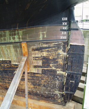
warships, submarines, uboats, passenger liners, sailing ships, fishing vessels, cargo ships, merchant ships, ship database
Website with searchable ship database about warships, passenger liners, merchant ships, photo galleries, technical details, stories, news and much more.
www.maritimequest.com
another "modern" rudder blade of the HMS Victory
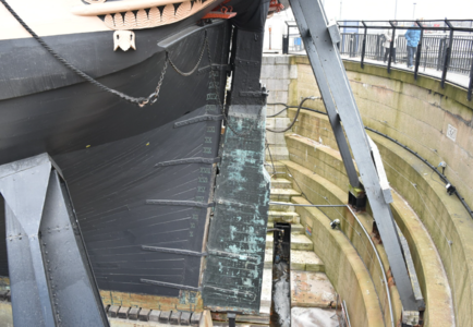
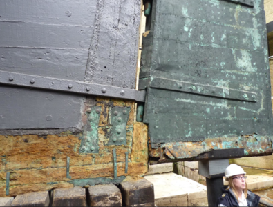
- Joined
- Oct 11, 2021
- Messages
- 740
- Points
- 403

Complete logical! It's not about right or wrong, this way or that way. It's just all about what you think will suit your ship the best.Peter, thank you for the comment! And I was thinking the same way too!
It was a dilemma for me - whether to opt for a slightly more complicated building process or to make it a bit thicker. In all the books about the S. Maria I have, the thickness of the rudder is the about same as the thickness of the sternpost, which is 5 mm in my case. When I tried the rudder from the kit (3 mm), it seemed too thin to me. So the optimal thickness could be around 4 mm. However, when considering a vessel of this size, it's easy to imagine a rudder that is about 300 mm thick. Therefore, I decided to take the simpler approach
And the hinges - in the kit they were even wider. I reduced wideness by 1 mm and calculated it approx according to zu Mondfeld recommendation - see the picture below:
View attachment 387454
But in general - let me sleep with your ideas, may be I will come to slight update of the rudder eventually
I reduced the thickness of my Santa Maria rudder because it looked to bulky in my eyes, however, considering the time period I don't know if that was even realistic or logical. To me it looked better. The same with the hinges, I reduced the width almost by half of the kitversion. Again, I liked the smaller hinges, not comparing it to the timeperiod of the ship.
Again, it's a masterpiece in the making! Keep up the great work!

Peter
- Joined
- May 1, 2023
- Messages
- 115
- Points
- 113

Dear @Uwek and @Ptèr,
After certain consideration, I have decided to try a slightly thinner version of the rudder blade. While changing the hinges on the ship's body might prove challenging, the rudder itself is an entirely independent component. It took me approximately half a day to refine it, assuming I had all the necessary models and materials prepared. I think that was worth the effort. Ultimately, I believe I will opt for the thinner version. However, in my view, both versions appear "plausible." After all, considering that there is limited knowledge about the vessels of the 15th century, it's hard to determine their exact appearance. My only ray of hope lies with Dr. Batchvarov (https://youtube.com/@kroumbatchvarov-archaeologist); perhaps he will shed some light on the matter someday...
What do you think?
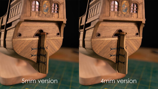


Not only that it is looking (personally) more realistic - you also reduced the weight of the rudder by 20% - easier to handle for the helmsman 
The thinner one is looking better
The thinner one is looking better


