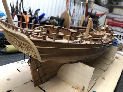
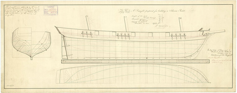
SEAGULL - POF in 1:48

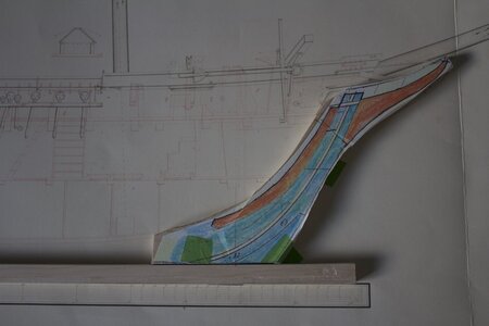
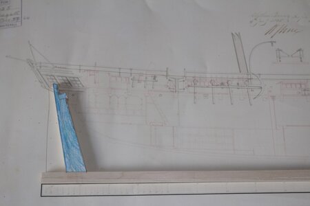
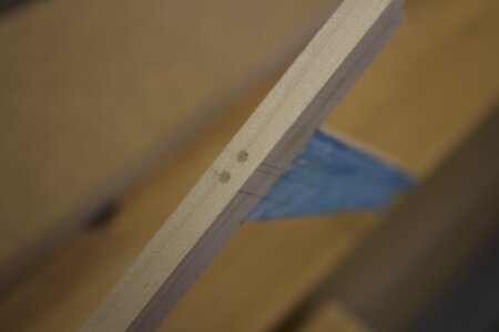
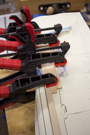
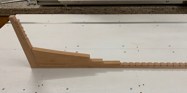
Keel and false keel nearing completion, just sanding to size. Then add dowels to provide additional fixing of the two parts. Stern parts templated and cut. Stem parts traced and wood joined to provide blank for cutting. Should lay down keel shortly.

Struggling to finally resolve frame spacing. Section midships show frames touching, also tapered on molded sides from 12” to 6” at top sides. Acknowledge the frame stations and plan section are a guide but should I build with no space, single space or double space. Closing in on needing to commit! Any recommendations?
 
I can't tell you how much I admire your commitment to making as true to an Admiralty model as possible given the exhaustive research and time you've put into the project. I am following with the greatest interest!

Pete
 
I can't tell you how much I admire your commitment to making as true to an Admiralty model as possible given the exhaustive research and time you've put into the project. I am following with the greatest interest!

Pete
Peter, thank you for following my build log. I wondered if you could assist by answering a few questions:-

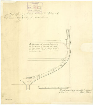
1. Above is a photo of a midships section of the Seagull. As I have stated the frames are shown touching each other. Do you think this would be the case for the entire length of the ship?

2. If this is the case the floor of the hold, in effect the bilge region, would be solid. I guess that there would not be a timbered floor in the hold?

3. The frames taper on the moulded face from 12” to 6” over the height of the hull. On the model the gap between the frames would be 1/8” or 3mm at the top side. I am concerned re planking and clamps etc. Any comments?

Thanks in advance J
 
I am afraid that you are assuming I have detailed knowledge and understanding that I don't actually have concerning these details. As flattering as that is I'm afraid it isn't very helpful to you. The drawings you sent in the PDF seem to give the clearest idea of how the frames are situated, the cant frames touching at the bottom while the others do not. Because the frames are laminated from several different pieces it is hard to tell what is part of what and if they are actually touching, or just very close together. I go with the latter. If you are close to Greenwich, perhaps a visit to study comparables is in order. Often just when I've made a decision of how some detail should be and go with that, some new information turns up and throws the whole thing into question once more. A problem often encountered in sorting out rigging practices between English, American and Continental ships of any given period. Make a decision based on the conclusion you reach with the best information you currently have and devil take the hindmost. The reality of these matters seems to be a moving target. I am just fascinated with what you are doing and admire it. I am no expert. The only remotely useful advice I can offer is don't let paralysis set in for want of the prefect, when the good will do.
You might contact Grant Walker at walker@usna.edu at the US Naval Academy and put the question to him, he is the reigning expert there in such matters and could perhaps shed some light on the subject for you. Use my name, not that I carry much weight, but at least he knows who I am.

Hope this helps, Pete :rolleyes:
 
Good evening followers and new watchers.

Not sure if this is a milestone but here goes……..

With the exception of completing the deadwood I have laid down the keel. From the photographs you will see I have positioned the stem and stern posts. These are a combination of the original plans 1829 and the alterations 1835.

Stem Post Alignment.jpg
The stem still needs a little more material removed and then sanded, particularly on the other sides where paper is attached.
Stern Post Position.jpg
The stem position is a datum as this is consistent between both sets of plans.

All parts have been tree nailed together, including the false keel.
Tree Nails Keel top Stern Post.jpg

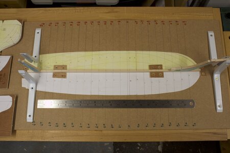
I have positioned the keel in a jig preventing movement in two directions, port/starboard and forward/aft including ensuring the stem and stern are vertical.

Overall Jig.jpg

The stern is not fixed as yet as the deadwood/counter arrangement needs to be finalised. Not sure about this bit yet studying Underhill sketches 23 A and B and contemplating next steps…. any advice and comments greatly appreciated.
 
Thanks for posting this log. It is very instructive and I am learning a great deal from you, even as you find your way in the dark. Perhaps not as dark as you sometimes seem to think it is. You are certainly lighting the way for me. Thanks,

Pete
 
The end of another week…… progress on model slow, but progress on reviewing next steps and sawing and sizing timber.

Building UP Deadwood - Stern.jpg

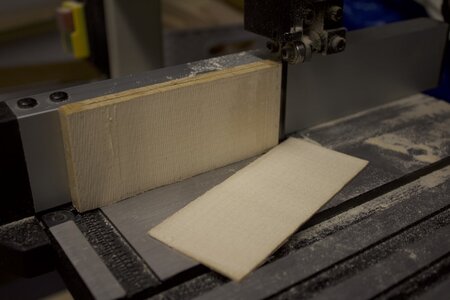
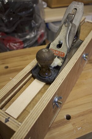
Sawing timber on bandsaw, planing and shaping using disc sander and hand planer. Photos below…..

Bandsaw.jpg
Planer 1.jpg
Planer 3.jpg

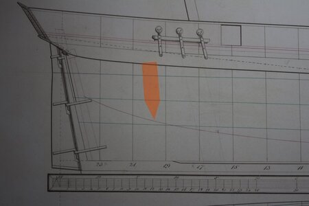
Frame sizes, moulded and sided finalised and working on the bow and stern cross frames initially as I remain perplexed about finding the rebate and the bearding lines, particularly the mid waterlines on the stern. One question….. would I be correct to ensure all the waterlines and level and the frame to deadwood/keel height adjusted accordingly to make the frame rebate align with the rebate on the keel and deadwood? Note the three green horizontal waterlines on the drawing below.

Stern Post Rebate Line.jpg

Above you may see my confusion…. the keel rebate line is horizontal along the keel and appears to run out between frame station 17 and 19, heading upwards towards the stern post. There appears to a small length of vertical rebate at the top of the stern post. Is the absence of a continuous rebate the fact that the hoods of the planking will terminate along the frame edge or am I missing something? Any help and observations greatly appreciated.
 
Your skill in wood working (wood engineering more precisely) is impressive. As are all the handmade jigs, shooting boards and other devices for accurate wood working. I'm being schooled just following you, Not just in making the model, but in making the necessary adjunct tools IN ORDER to make the model! I wish you lived nearby. But then you'd probably get tired of me looking over your shoulder. :rolleyes:
I look forward to the next installment. I'm hooked!:D

Pete
 
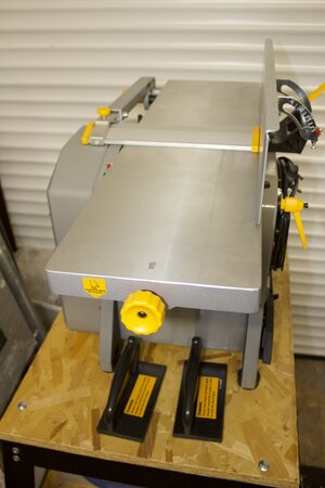
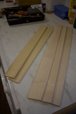
Having purchased some Sycamore and Obeche "lumber" I brought this down to near size using the band saw. However my hand planer thicknesser, see earlier photographs, was quite strenuous and frustratingly slow. I purchased a low cost planer thicknesser and produced five pieces within 30 minutes. These are approximately 6.5mm thick equivalent to 12.5" on the real vessel.

Planer Thicknesser.jpg Sycamore and Obeche %22Lumber%22.jpg

I plan to use the Sycamore for the keel and lower futtocks and the Obeche for the upper futtocks in the top side positions. The frames will taper from 12.5" (6.5mm) to 6" (3mm) on the moulded sides with different tapers representing the cross piece and the half floor variants.

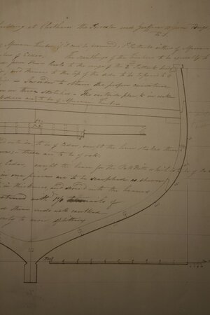
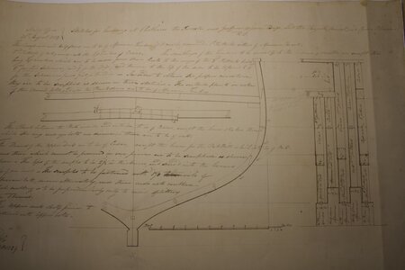
One question for my followers……Am I correct that the inner surface will be smooth along the hull length? The section of the midship area shows no Keelsom.

Section Midships 1.jpg Section Midships 2 Landscape.jpg

Thanks….Seagull Shipwright.
 
but there is a keelson shown in the contemporary drawing - and also thick stuff planking

View attachment 394269

Uwe, thank you so much for looking over my shoulder. It’s a great help. When you last bought these drawings to my attention, I had already liaised with the RMG and purchased, what I was led to believe was a complete set of the drawings. However the contemporary drawings you referred to had one more, the one you sent me above, that give some key information on the internal planking and beams. I will use this information going forward to cut the notch in the frames, detail the bottom of the frames and complete the internal planking.

One question why do you call these “contemporary drawings”?

Once again many thanks for your help and expertise.

Seagull Shipwright
 
One question why do you call these “contemporary drawings”?
If I could respond for Uwe as I once had the same question... contemporary can mean 'the present time', but it can also mean 'the same time as another', and that's the way Uwe is using this word. For example, "he was a contemporary of Van Gogh." In this case the drawing Uwe was showing you was developed at the time of the original ship.

Hope this helps!
dockattner and Uwe,
Thank you for adding your knowledge to this topic. Your response does put the information into context. The 1829 documents appear to be proposals for the construction of the original schooner packets. Note in the event only Seagull was built. The 1830 documents are more detailed specifications at the time of the build, note she was launched mid 1831. These are the contemporary plans and include Uwe’s response above. Finally the 1835 documents relate to the refit where she was converted to the brigantine from the original schooner along with hold and tween deck alterations.

Thanks Seagull Shipwright
 
Good afternoon advisors and followers…. more advice needed please! Whilst I am progressing with my frame construction (cross pieces and half floor arrangements now understood!). I am studying the aft section of my build.

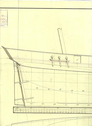
On the original 1829 proposals (see photograph)

1829 Proposal - Aft Side View.jpg

The position of the main deck is clear (shown in red).
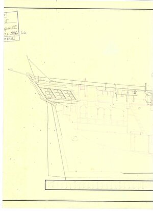
In the contemporary drawing dated 1830, at the time of the construction the side elevation (see photograph).

1830 Drawing - Aft Side View.jpg

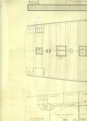
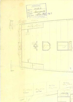
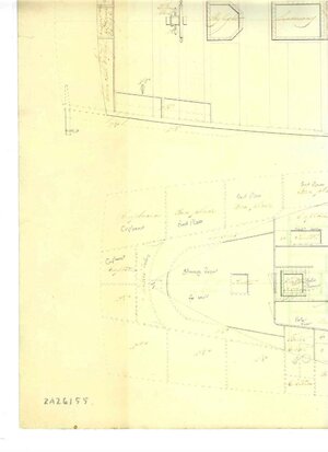
The deck arrangement is similar to the proposals and note the position of the wheel (schematic). The Main Deck and Tween Deck drawings are shown below:-

1830 Drawing - Main Deck.jpg 1830 Drawing - Tween Deck.jpg

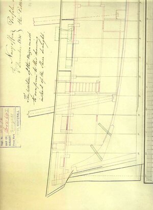
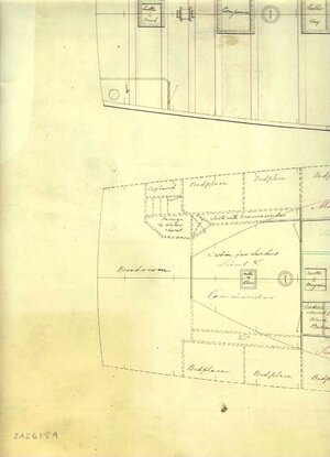
There are no port or starboard galleries and no structure shown, around the wheel. Those following will be aware of the re-fit in 1835. Reading around this topic it appears that many vessels were converted at this time to capitalise on the increased passenger traffic to North America and Australia. On the 1835 drawing (see photograph below),

1835 Drawing - Aft Side View.jpg
You can see some detail in red of the new cabins in the aft section. Would it be correct that windows would be let into the transom of this accommodation?

There is also windows (3 off) port and starboard but these are level with the original deck? It is possible windows could wrap around and pass across the counter area either side of the rudder box? I cannot see any new structure on the original deck to form a Poop Deck? and cabins with a higher headroom are not shown.
However the ropes and blocks are shown in this area and would be in the way for this notion! Are these windows a decorative feature? Please see below the plan view of the main and Tween Decks that do not show any additional structure associated with these windows.

1835 Drawing - Main Deck.jpg 1835 Drawing - Tween Deck.jpg

Any input greatly appreciated as always……..Seagull Shipwright - realising how little I know on this subject!!
 
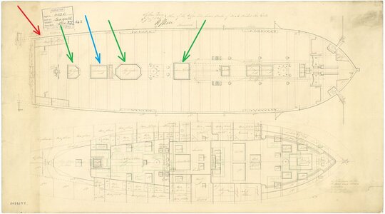
I try to interpret these drawings, but I am not 100% sure

They did not change the height of the deck

The red arrow - these are fake windows - the stern was sometimes decorated like this to give the impression of a much bigger vessel - like a frigate - see also at the end the comment related to Coureur

The blue arrow is the stairway down - btw they closed all the gunports, only one near the stairway is open as an comfortable way to enter the ship deck

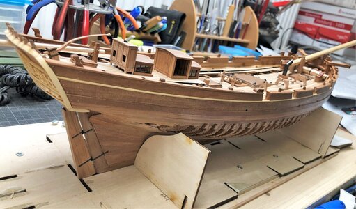
The green arrows are decklights to bring day light into the lower deck - so I guess all the cabins got the daylight only partly via these glased deckhouses - see also the Coureur

seagull.jpg

seagull 4.jpg


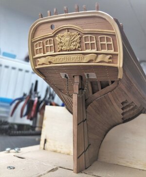
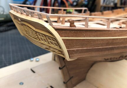
My Le Coureur had this also

fake window at the stern - the deck would be at the half height of the window - only fakes made out of wood without glas

IMG-7057.jpg IMG-7120.jpg

IMG-7135.jpg


IMG-6537.jpg IMG-6541.jpg

IMG-7097.jpg IMG-7821.jpg

IMG-7822.jpg
 
I try to interpret these drawings, but I am not 100% sure

They did not change the height of the deck

The red arrow - these are fake windows - the stern was sometimes decorated like this to give the impression of a much bigger vessel - like a frigate - see also at the end the comment related to Coureur

The blue arrow is the stairway down - btw they closed all the gunports, only one near the stairway is open as an comfortable way to enter the ship deck

The green arrows are decklights to bring day light into the lower deck - so I guess all the cabins got the daylight only partly via these glased deckhouses - see also the Coureur

View attachment 396738

View attachment 396737


My Le Coureur had this also

fake window at the stern - the deck would be at the half height of the window - only fakes made out of wood without glas

View attachment 396739 View attachment 396740

View attachment 396741


View attachment 396742 View attachment 396743

View attachment 396744 View attachment 396745

View attachment 396746
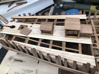
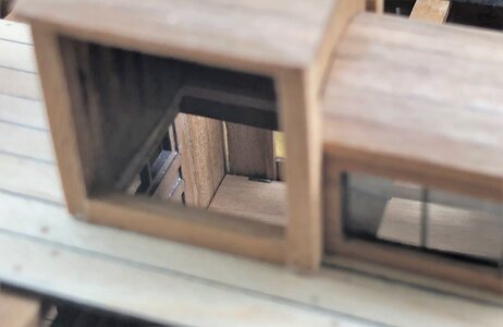
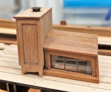
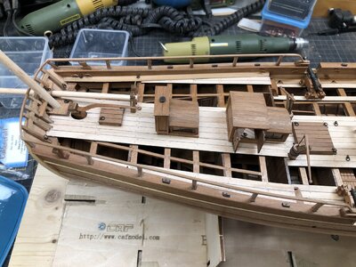
Uwe, Thank you for the fast response and can I complement you on your model quality. What are the woods you are using for the decking and deck furniture? Is it your intention to leave the areas incomplete to show the construction and interior detail or are these work in progress?

I noted the modified gun ports you highlighted. Thanks again Seagull Shipwright.
 
Hi all followers…..just nearing the completion of my first three frames midships, forward and aft last square frames. The idea is to align and see where the bearding and rebbit lines are as well as height of the waterlines above the keel. Any points to look out for?

Just completed the following book ….”Travelling by Sea in the Nineteenth Century”. interior design in Victorian passenger ships. By Basil Greenhill and Anne Gifford. 1972. ISBN 0 7136 1302 5. 78 photographs with descriptions. Informative read for cabin and salon construction.
 
Good evening followers and advisory experts. Things are progressing nicely (I think!). Just a photo of frames under construction…..]O[ Frame with futtock dowel.jpg
Started to position the ]O[ midship square frame on the keel.

]O[ Frame on Keel with Rule.jpg
You can see above the keel held on its initial jig with the ]O[ frame supported using the two right-angle pieces and small clamps. The water lines have been transposed across the frame holdings and sidings. According to the plan the first water line is 5'-0" (31mm on model) above the bottom of the keel/false keel as shown in the next photograph.

]O[ Close up with rule -2.jpg

Note the floors have not been sized but will be 20.6mm from the datum, that will be about where the small horizontal mark is on the center line of the frame. The garboard plank will run along the bottom on both sides and the rebate will be along the upper edge of the keel, as per the drawing below.

ZAZ6157-Seagull1831-Lines.jpeg

I am concerned about the relatively small area of contact between the frame and the keel, particularly since the frames are drawn immediately adjacent to each other.

AT LAST…..The Question….. Should I use a tree-nail through the Keelson and frame and into the keel as a blind fixing to hold and give more support? Alternatively should I take out some frames and use packing pieces and use these to provide additional surface area for adhesive and support to the frames?

Is there any other options, without compromising the integrity of the original design. All guidance greatly appreciated.

Seagull Shipwright.
 
Back
Top