The Build Board
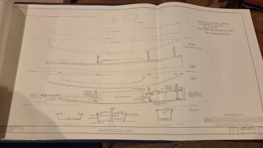
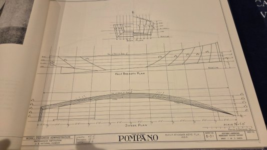
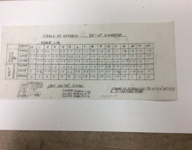
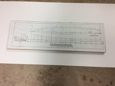
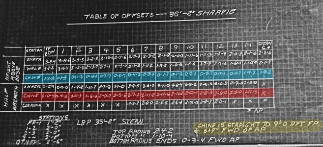
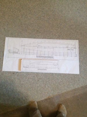
Serious Ship Model Builders agree that a quality ship model accurately displays the hull lines of the real vessel, or at least an accurate drawing of it. In our case we are fortunate that Howard Chapelle’s Table of Offsets is based on actual measurements taken from a real boat and so far I have been careful that my lines drawing is an accurate representation too.
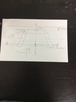
Ship model building is an exercise in Solid Geometry, and a well made building board allows accurate measurements in three dimension in three dimensions which for convenience well call x,y,and z.
X, Length
Y, Width
Z, Height
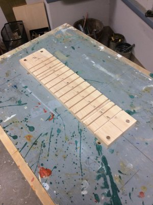
To start, I selected a piece of 1” (nominal) lumberyard softwood from my stash. I checked it on the machined top of my table saw to make sure it was flat. Since wood changes with humidity and temperature using a piece that had been in my woodpile meant that it was acclimated to the workshop’s environment.
Next with an .030” slitting blade on my Byrnes Saw I cut a straight slot down the length of the wood. It was about 1/8” deep but exact depth is unimportant. Without my Byrnes saw I could have used my full sized table saw but the groove would have been wider.
This slot down which will be under the centerline of the hull is the reference point for dimension Y (width).
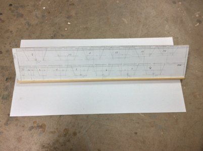
Next, I marked out lines perpendicular to the slot at the location each of the 14 Table of Offsets/ lines drawing stations. In doing this, care must be taken to avoid “Tolerance Stackup.” If each line is off by .010” in the same direction then the 14th will be .14 too long or too short. Two ways to avoid this:
1. Make a table for the location of each line with the Fore or Aft Perpendicular being Zero. Then mark each line measuring from that Zero point.
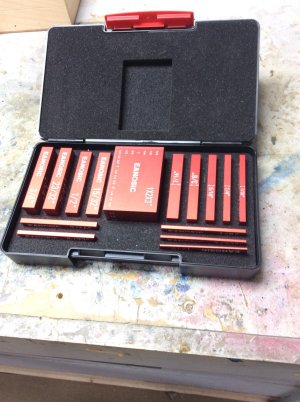
2. The method that I used. I recently bought a set of gage blocks that used in combination can be stacked to indicate dimensions from 1/16” to 4” in 1/32” increments. I use these all the time and they are a huge improvement over previous measuring methods. Clamping a square to the board, I drew two lines across, one for the Forward Perpendicular (FP) and one for the After Perpendicular (AP). Using a ruler, great care was taken to ensure that these first two lines were spaced correctly (13-1/16”). I then clamped a machinist square to the line representing the FP and stacked the necessary gage blocks for the correct spacing for station 1 and marked that line. I did the same for subsequent stations by each time moving the square to the last marked station and stacking gage blocks. The final check was to see if the distance between station 14 and AP was correct.
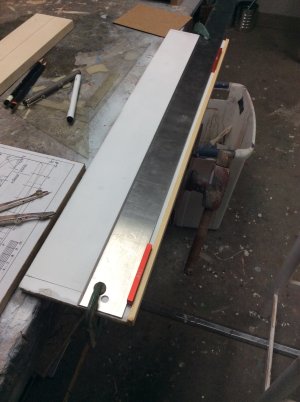
I then stood the board upright in my carpenters vise, extended the lines across the side of the board, and using a gage block drew a second line spaced 1/8” from the other.
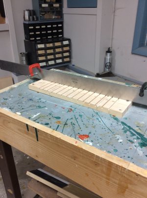
With an aluminum angle screwed to the board and attached to the full sized table’s miter gage I sawed a 1/4” deep groove across the board at each of the 14 stations.
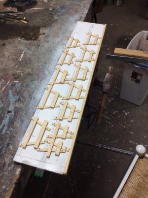
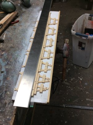
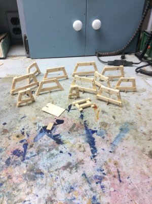
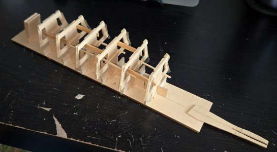
These stations were to be used for mounting the 14 molds correctly along Dimension X (length).
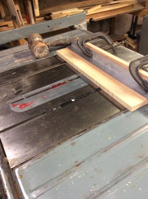
The grooved board was then screwed to the top of a wooden topped work table using a flat head wood screw at each corner. Again, the board was checked for flatness and level.
This flat, level surface provided an accurate reference for the third dimension; Dimension Z (height).
The finished board. Cost, $0.00.