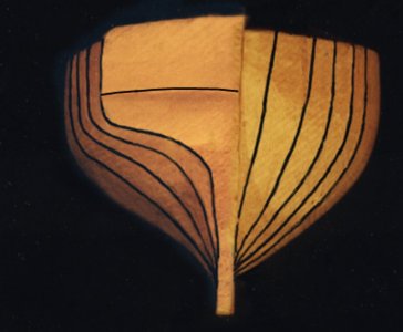
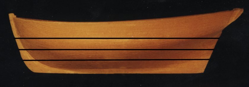
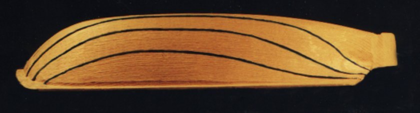
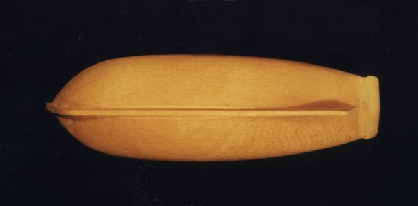
• Ships of Scale has incorportated an extra level of security when you log In. Please follow on-screen prompts to acknowledge that you are not a robot via a "Check Box" or a "Pictorial Check Box Puzzle". This is needed due to higher level of AI Activity Security.
  • SUBSCRIBE TO SHIPS IN SCALE TODAY!

    The beloved Ships in Scale Magazine is back and charting a new course for 2026!
    Discover new skills, new techniques, and new inspirations in every issue.

    NOTE THAT OUR NEXT ISSUE WILL BE July/August 2026
  • Win a Free Custom Engraved Brass Coin!!!
    As a way to introduce our brass coins to the community, we will raffle off a free coin during the month of August. Follow link ABOVE for instructions for entering.

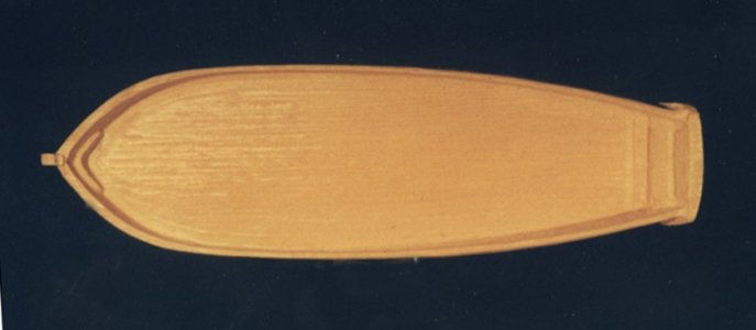
SHARPIE

I missed posting last weekend due to some family problems
so I’ll try to catch up today.

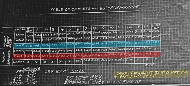
When we left off I had copied the Table of Offsets for the hull that I plan to model from Chapelle’s American Small Sailing Craft Book. The hull of a boat or ship is of course a three dimensional object. The Table of Offsets typically provides dimensions for two of these; heights above a base line and half breadths measured from the centerline. The builder needs to use these to determine the shape of “stations” spaced along the length of the hull and where each station is located. This is done by first drawing a grid defined by drawing vertical lines representing each station along the hull’s longitudinal axis and again for a half breadth view. Measurements from the Table of Offsets are then plotted as curves on the two views. Once this is done, the third view, body plan, can then be plotted form information from the first two views to yield molds (frame shapes) to build the boat.

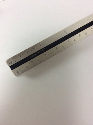
In our case, Table of Offsets represents measurements taken from a real boat and tabulated in the conventional format of feet, inches, and eights. My chosen scale is 3/8= 1ft-0” so these dimensions need to be divided by a factor of 32 for the model. The easiest way to do this is with an Architect’s Scale. This allows measurements to be read directly.

IMG_3266.jpeg

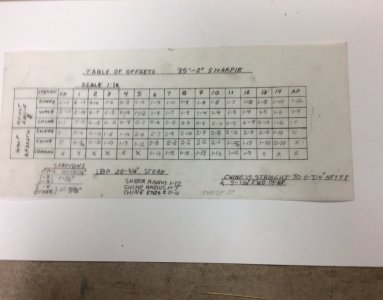
But in this case I used a different method. Using Excel I wrote a simple routine on my computer that converted Feet, Inches, and eights to inches and sixteenths at 1:16 scale. Why 1:16? Here in Duluth we have a company that makes inexpensive high quality copies of architectural drawings. Using this process they can also make half sized drawings. The double sized lines drawing is easier to draw and the tolerance for information shown on the drawing is halved too. The point of a well sharpened pencil may be as small as 1/64” but when shown on the half sized drawing the line drawn becomes 1/128”.

And here’s the new table in inches and sixteenths @ 1:16 scale. Next, we draw a lines drawing

IMG_3175.jpeg
 
Today, I’ll discuss the next step in building my Sharpie model: the lines drawing. Lines drawings seem to be mysterious for many ship model builders. Each profession seems to delight in conventions that confuse, like lawyers using Latin. Actually the lines drawing is really a simple way of depicting a complicated shape.

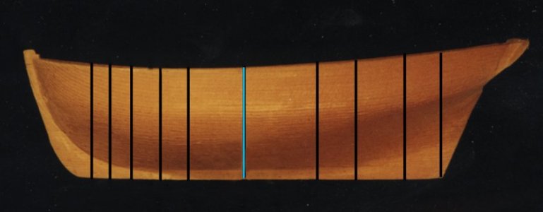
First of all the lines drawings is a common three view drawing, also known as an orthographic drawing. An orthographic drawing shows an object in three separate views: a side view, a top view and an end view. A naval architects titles these three views as follows: a side view is called a sheer view, a top view a half breadth and an end view a body plan. Since the vessel is symmetric there is no need to show both sides on the drawing. This causes the end view or body plan to look strange as a view from the bow aft and the stern forward are both included on this one view.

A lines drawings converts the digital information from the table of offsets into a useable set of lines as the offsets define points along the surface of the hull in three dimensional space. By plotting them on the three orthogonal views and connecting points along a line for each view we can build a model. Each view shows only one “true view” of a line. The same line then shows up as a straight line on the other two views. For example, a waterline shows up as a curve on the half breadth. The same waterline shows up on a horizontal straight line on the body plan and sheer plan.

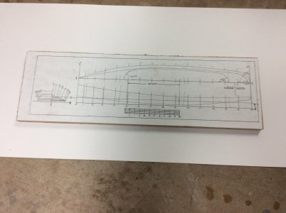
As a noted professor of naval architecture recently told me, “nobody draws lines by hand anymore. That is nobody except me. I once used an early CAD program to make a lines drawing, but I’d rather spend my time building models than staring at a computer screen. I enjoy drawing lines drawings by hand and drew the one that way for my sharpie (first photo below). If you have the patience to use CAD there are some advantages; a major one being the ability to draw at a large scale, even 1:1 and then print to your model scale. Lately, 3-D modeling seems to be the new thing. While I see advantages for those designing a new ship for a model I would prefer a 2-D system that produces a conventional lines drawing.

The key to any lines drawing is an accurate rectangular grid. Parallel lines must be parallel and 90 degree corners dead square. Several years ago I bought a 36” long quality straightedge. By first drawing a baseline and then using large C clamps to clamp the straightedge along the baseline I can draw true 90 degree corners using a large triangle. Once the grid has been drawn, it’s a matter of plotting and connecting the points from the Table of Offsets. A quality drafting compass is valuable for transferring offset points and transferring points between views

Drawing a fair line through a series of points is an art since no two draftsmen will do it the same unless all points line up exactly; something that rarely happens. This can require trial and error that involves lots of erasing. A rotary electric eraser becomes an essential tool. I am fortunate to own an abbreviated set of ships curves and a half dozen was more than enough do draft the Sharpie’s hull. A wooden spline secured with lead weights or even small nails will work just as well. I first make a pencil draft on ordinary paper and then an ink on Mylar tracing. As mentioned earlier I draw my lines to twice modeling scale and then have a half size copy made by an architectural copier.

Roger

IMG_3141.jpeg
 
Last edited:
First of all the lines drawings is a common three view drawing, also known as an orthographic drawing. An orthographic drawing shows an object in three separate views: a side view, a top view and an end view. A naval architects titles these three views as follows: a side view is called a sheer view, a top view a half breadth and an end view a body plan.

i have some questions on the views of a hull and the lines
starting with the side view

bodyplan.jpg

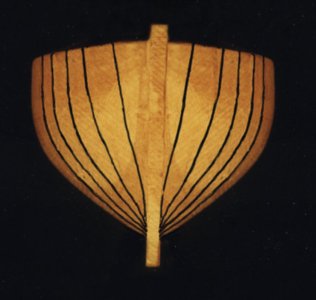
if these lines are projected as a front view they would look like this right? and you seeing the hull from the bow to midship


bow.jpg

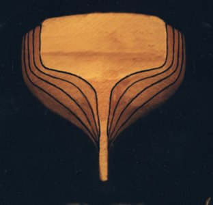
standing at the stern you would see this

body stern.jpg

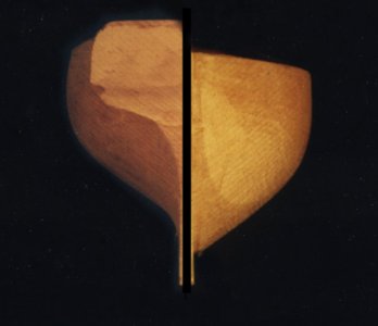
the draftsman splits the views

figure 4.jpg

and draws it like this which is called the bodyplan. Question are the line locations you see in the side view at the location of frames or placed there according to the shape of the hull or both? How are the locations determined?

body bow.jpg
 
Last edited:
going back to the side view if the lines are drawn horizonal rather than vertical

figure 5.jpg

they would look like this viewed from the bottom of the hull


figure 6.jpg

a side view, a top view and an end view.

is the top view really looking from the bottom of a hull


figure 3.jpg

or is the top view looking down on the hull like this which is the deck view

deck view.jpg
 
Dave, Thanks for your post.

Your easy question first. You are correct, the half breadth is a bottom view of the hull not a top view.

Now, the more difficult question. In the context of building a vessel where a lines drawing was prepared instead of a half model it was a preliminary design document, used to generate a table of offsets for the mold loft. The order of events was: Lines drawing-Table of Offsets- Mold loft.

To build my model, events are reversed: Table of Offsets- Lines Drawing- Mold Loft.

So, the lines drawing needed only to provide enough information to allow the design to be laid down on the mold loft floor. As we have discussed on this and other forums actual framing on real ships was closely spaced so trying to include every frame on the lines drawing would be unnecessary and add possibly confusing detail to the drawing. The spacing and number of body plan sections and waterlines would therefore depend on the naval architect/draftsman/loftsman’s needs to accurately lay down the design on the mold loft floor.

There were of course exceptions. As Chapelle has written the best information for model building is a “takeoff” of an actual hull. My sharpie model is based on a takeoff. Chapelle measured an actual boat in the late 1920’s. As sharpies are built without real frames the 14 stations on the drawing reflect Chapelle’s judgement. Chapelle includes a note on his table of offsets instructing potential builders to prepare molds for each of the 14 stations on his lines drawing.

A somewhat related response to your posts involves the question of “true views”. A problem with orthographic drawings occurs when a line is out of plane with the surface of the drawing. It then is shown foreshortened. The cant frames shown on your model are an example of this. There are graphic solutions to this problem involving creation of auxiliary views. If the loftsmen knew the location of the cant frames they could loft their shape using waterlines from the lines drawing.

While my Sharpie does not have cant frames, neither the chine or sheer line on the lines drawing are true views. This will come into play and be dealt with as the build goes forward.

Roger
 
Question are the line locations you see in the side view at the location of frames or placed there according to the shape of the hull or both? How are the locations determined?

English practice. Probably starting in the 17thC - 18thC. and half of 18thC.
Design plans. The starting key is the midship/deadflat. It is assigned as zero (a circle with one or two cross hash).
It is the midline one a pair of frames or simple to type a "bend". The design starts with a set of rules. Up until the 1750's these were rigid design limits that set the length x breadth x depth as well as the scantlings of the individual components. These were the Establishments. R&S defined the sided dimension of a bend and its space.

The key for the mold loft was the stations. Every station was the midline of a bend. A pattern was made of every timber of a station bend. Sirmarks were placed on the patterns for the midlines of the bends between the stations. The filling frames were shaped by yard craftsmen.

The stations were arbitrary in frequency. Often it was Q3 bends - or Q4 bends - sometimes Q2 bends. (I found one plan of Roebuck 1774 with a Q1 bend interval - a treat to build if it were a unique subject. Alas, it is way too far from being a new subject.) The stations are numbered to reflect the total number of frames between.
0 - C - F - I - M - P-... / 0 - 3 - 6 - 9 - 12 -15 ... is Q3.
0 - D - H - M - Q - U... / 0 - 4 - 8 - 12 - 16 -20 ... is Q4
The "1" was a weird shape. "J" was most often skipped. So was "W" often skipped. The English used a unique floor timber placement. It was always outboard of the station. A skip step had to be done at the midship to either lose or add a frame.
On large ships the midship bend may be repeated of the next one out -so there is often silly numbering there.

So in a design plan the stations reflect the framing.

With a "as captured" or "we lost the original and are taking off from the actual hull" plans done when in drydock - the stations have nothing to do with the actual framing. Zero - midship - was a guess. The next station was usually a 10 foot interval until the slope became significant. Then 5 foot and then 3 foot. No help at all for lofting for scratch POF. HIC may have preferred take off plans - I hate them.
 
On actual British Dockyard practice, I yield to Allan and Dean. My interests slant towards merchant vessels and artisan built smaller craft as well as vessels built here on the Great Lakes.

For these vessels it is remarkable how many were built using tables of offsets recorded from half models. This includes many that we associate with lines drawings including the Great Clippers built in the USA and surprisingly Great Britain. See works by Carothers, McGregor and Chapelle’s National Watercraft Collection. These lines drawings were often drawn after the vessels were built or by later researchers using Tables of Offsets or the half models. For example it was recently discovered that at least some of the drawings in Webb’s well known portfolio date from 1895, long after he left the shipbuilding business.

One might think that the advent of iron and steel construction would have signaled the end of the half model but here on the Great Lakes this was not the case. For example, the Lake Superior Maritime Museum has on display a half model of a c1900 Lake freighter. The model has been cut for drawing body plan sections.

Roger
 
One of the frustrating and tragic aspects of half hull design models was when I read that Donald McKay's servant used his models as kindling. The not so famous ships have been lost to history.
 
volunteering years ago in the library of the Inland Seas museum when it was in Vermilion i came across many tables of offsets and always wondered how to read them.
another question if you do not mind,

highlighted in yellow it says the chine is straight why are all the numbers different in the offsets i would think it would be the same number if the chine is straight

chine.jpg


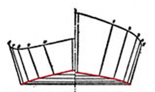
looking at the bodyplan the chine in red is not straight it rises fore and aft and curves to the shape of the hull, so what is the yellow highlighted area saying?

red chine.jpg
 
It’s the orthographic projection. The chine is “moving” in two dimensions, for and aft and side to side. the numbers in the table separate this three dimensional line into two separate two dimensional shapes. In other words, a bottom view of chine in the half breadths and side view of the same line in the height above the baseline.

Chapelle is referring to the shape of the chine in the side or sheer view. When you plot the offsets for these heights on the side ie; sheer plan it should slope as straight line for the first 9 ft aft of the stem ( on just this one view) and when I drew the lines drawing it did.

Re the body plan; again, the stem is moving in two dimensions so the chine does not appear as a “true view.” When I layout planking down the road I intend to draw a planking expansion so we’ll see what a true view of the chine looks like.

Roger
 
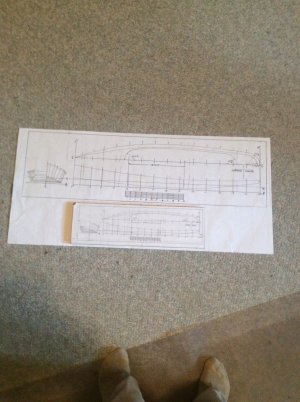
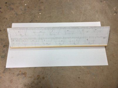
Scale: As I posted above the lines drawing for my sharpie model was drawn to a scale of 1:16 with a half size print made by an architectural copy machine to arrive at a scale of 1:32. The photo below shows the two drawings compared.

The 1:32 scale drawing appears much smaller than one half the size of the original 1:16 scale one. This is because linear dimensions (lengths of individual lines) are half their original length but the AREA of the drawing is only 1/4 the area of the original (1/2x1/2=1/4. Likewise the dimensions of a box surrounding the finished model will result in a volume of only 1/8 of a model built to 1:16 scale. 1/2 cubed =1/8.

As the opposite is true there is a tension between selecting a scale large enough to show derail but small enough to display comfortably. Model size is a cubic function of scale. For models of small craft, say less than 50ft I consider 1:32 to be the ideal scale.

Roger

IMG_3306.jpeg
 
The Build Board

Serious Ship Model Builders agree that a quality ship model accurately displays the hull lines of the real vessel, or at least an accurate drawing of it. In our case we are fortunate that Howard Chapelle’s Table of Offsets is based on actual measurements taken from a real boat and so far I have been careful that my lines drawing is an accurate representation too.

Ship model building is an exercise in Solid Geometry, and a well made building board allows accurate measurements in three dimension in three dimensions which for convenience well call x,y,and z.

X, Length
Y, Width
Z, Height

To start, I selected a piece of 1” (nominal) lumberyard softwood from my stash. I checked it on the machined top of my table saw to make sure it was flat. Since wood changes with humidity and temperature using a piece that had been in my woodpile meant that it was acclimated to the workshop’s environment.

Next with an .030” slitting blade on my Byrnes Saw I cut a straight slot down the length of the wood. It was about 1/8” deep but exact depth is unimportant. Without my Byrnes saw I could have used my full sized table saw but the groove would have been wider.

This slot down which will be under the centerline of the hull is the reference point for dimension Y (width).

Next, I marked out lines perpendicular to the slot at the location each of the 14 Table of Offsets/ lines drawing stations. In doing this, care must be taken to avoid “Tolerance Stackup.” If each line is off by .010” in the same direction then the 14th will be .14 too long or too short. Two ways to avoid this:

1. Make a table for the location of each line with the Fore or Aft Perpendicular being Zero. Then mark each line measuring from that Zero point.

2. The method that I used. I recently bought a set of gage blocks that used in combination can be stacked to indicate dimensions from 1/16” to 4” in 1/32” increments. I use these all the time and they are a huge improvement over previous measuring methods. Clamping a square to the board, I drew two lines across, one for the Forward Perpendicular (FP) and one for the After Perpendicular (AP). Using a ruler, great care was taken to ensure that these first two lines were spaced correctly (13-1/16”). I then clamped a machinist square to the line representing the FP and stacked the necessary gage blocks for the correct spacing for station 1 and marked that line. I did the same for subsequent stations by each time moving the square to the last marked station and stacking gage blocks. The final check was to see if the distance between station 14 and AP was correct.

I then stood the board upright in my carpenters vise, extended the lines across the side of the board, and using a gage block drew a second line spaced 1/8” from the other.

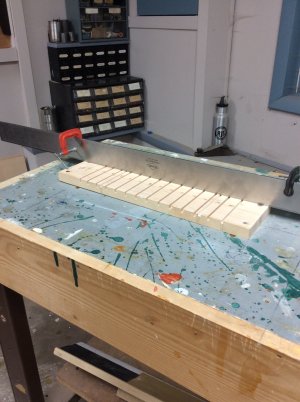
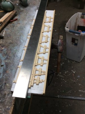
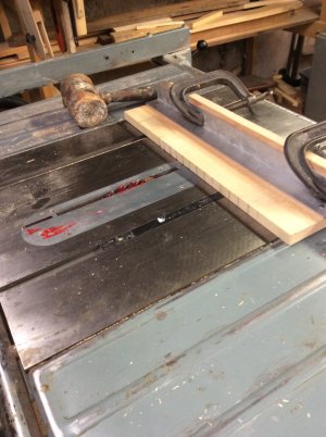
With an aluminum angle screwed to the board and attached to the full sized table’s miter gage I sawed a 1/4” deep groove across the board at each of the 14 stations.

These stations were to be used for mounting the 14 molds correctly along Dimension X (length).
IMG_3272.jpeg

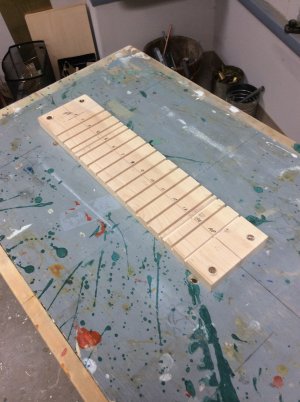
The grooved board was then screwed to the top of a wooden topped work table using a flat head wood screw at each corner. Again, the board was checked for flatness and level.

This flat, level surface provided an accurate reference for the third dimension; Dimension Z (height).

The finished board. Cost, $0.00.
IMG_3302.jpeg
 
Further to my previous post here are a couple more photos :

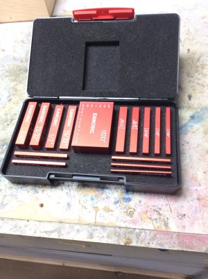
The first I my set of gage blocks, bought on Amazon. Many sets to choose from including metric ones. Cost, less than $40.00
IMG_3154.jpeg

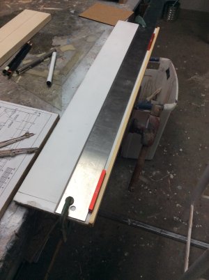
Next a photo of checking the build board for flatness. An aluminum angle (out of sight) is fastened to it with a pair of wood screws. An accurate straight edge, another useful ship modeling tool, is then clamped to the angle to check the board

IMG_3288.jpeg

Note the two shallow “extra” grooves in the board are for the boat’s two permanent bulkheads. Neither is located at one of the 14 mold locations.

Roger
 
Molds aka Moulds

The dictionary defines a mold as a temporary form about which planking is bent to build a boat.

Real sharpies were once built by first cutting the side planking and then bending it around just one mold before nailing it to the stem and transom. Where more than one plank was required for each side the planks would have to be fastened together before being bent. A credible model of a Sharpie could be built this same way.

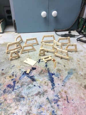
But we are not building just A sharpie. We are building a specific one that Howard Chapelle measured. Chapelle’s table of offsets includes dimensions for 14 stations so we will require a mold for each one. Model builders consider that the Sharpie has a simple hull. Howard Chapelle has commented that the Sharpie hull is graceful. Therefore, is it possible to build an ugly Sharpie? Apparently it’s very easy. A famous ship model building organization sells plans for a “Generic East Coast Sharpie.” Well, the model built from them certainly is well, “generic.” My objective is to build a model that accurately displays the graceful lines that Chapelle recorded. That means holding tight tolerances. At 1:32 scale, 1/32 inch represents 1”. Chapelle measured lines on the actual boat to 1/8” or .004” at model scale. That’s impractical for me but I believe that a goal of 1/64” might be doable. Anyhow, I’ll keep to less than the 1/32”.

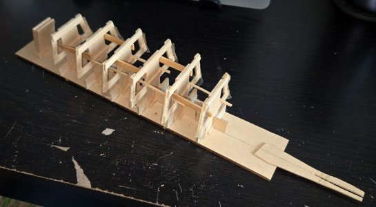
Like real flat bottomed boats the model will be built upside down. This requires some getting used to as sheer line on the lines drawing is now higher than the boat’s chine!

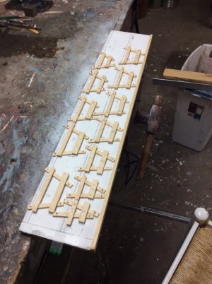
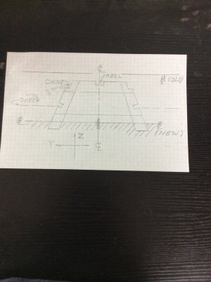
All 14 molds are of the basic trapezoidal shape, A sketch (not to scale) of a typical mold follows:

IMG_3378.jpeg

Some points to consider: First of all, the mold defines two of the three dimensions; Y, width and Z, height. The third dimension, X, length is determined by the groove into which each mold is inserted along the build board. Careful readers may remember that I cut an 030” groove down the length of my build board. The crosshatched peg extending from the bottom of the mold into the build board is a piece of 1/32” plywood that registers the mold’s location in the Y dimension to make sure that the centerline along all molds runs in a straight line. And last, there are two baselines, new and old. The new baseline is of course the top of the build board with everything now measured from there. The old one is no longer used.

Roger
 
Back
Top