


Part 20 Jib Boom
For me, the rigging around the bow, bowsprit, jib boom, and flying jib boom is the most complicated and challenging to do because of the crowded lines. The below two figures showing the details of rigging for the jib boom and flying jib boom were copied from “The Boys Manual of Seamanship and Gunnery” by C. Burney which can be found on the web (There are a number of books on rigging and seamanship from the 1800's that are available for free online and can be read on the books.google.com web site. ). I followed this rigging scheme since it is consistent with lithographs of sloops of war from the period of the Austin.


After the bowsprit cap was installed, the jib boom was passed through the cap and fastened to the saddle with a lashing. Next I constructed the dolphin striker and whiskers. Whiskers served to spread the guys form the jib boom and flying jib boom in the absence of a sprit sail yard . They were either hooked or lashed to the bowsprit and I choose to hook them into eyes. The two whiskers together, port and starboard, are the same length as a sprit sail yard, if carried. The whiskers and dolphin striker are shown below:

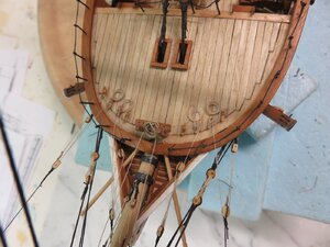
Rigging began with the martingale stay to the bottom of the dolphin striker and the back stays set up with tackles to eyes in the bow. Next, lifts were rigged to position the whiskers and then the jib boom guys were added, all with the associated tackles. Finally horses were put in place for the jib boom. This rigging is shown in the below 3 figures:


Notein the figures the black metal bracket at the end of the jib boom for supporting the flying jib boom. Two pieces of brass tubing were soldered together and painted black. One end slid over the end of the jib boom, and the flying jib boom will pass through the other end when it is installed.
For me, the rigging around the bow, bowsprit, jib boom, and flying jib boom is the most complicated and challenging to do because of the crowded lines. The below two figures showing the details of rigging for the jib boom and flying jib boom were copied from “The Boys Manual of Seamanship and Gunnery” by C. Burney which can be found on the web (There are a number of books on rigging and seamanship from the 1800's that are available for free online and can be read on the books.google.com web site. ). I followed this rigging scheme since it is consistent with lithographs of sloops of war from the period of the Austin.
After the bowsprit cap was installed, the jib boom was passed through the cap and fastened to the saddle with a lashing. Next I constructed the dolphin striker and whiskers. Whiskers served to spread the guys form the jib boom and flying jib boom in the absence of a sprit sail yard . They were either hooked or lashed to the bowsprit and I choose to hook them into eyes. The two whiskers together, port and starboard, are the same length as a sprit sail yard, if carried. The whiskers and dolphin striker are shown below:
Rigging began with the martingale stay to the bottom of the dolphin striker and the back stays set up with tackles to eyes in the bow. Next, lifts were rigged to position the whiskers and then the jib boom guys were added, all with the associated tackles. Finally horses were put in place for the jib boom. This rigging is shown in the below 3 figures:
Notein the figures the black metal bracket at the end of the jib boom for supporting the flying jib boom. Two pieces of brass tubing were soldered together and painted black. One end slid over the end of the jib boom, and the flying jib boom will pass through the other end when it is installed.


 s
s


")

