• SUBSCRIBE TO SHIPS IN SCALE TODAY!

    The beloved Ships in Scale Magazine is back and charting a new course for 2026!
    Discover new skills, new techniques, and new inspirations in every issue.

    NOTE THAT OUR NEXT ISSUE WILL BE July/August 2026
  • Win a Free Custom Engraved Brass Coin!!!
    As a way to introduce our brass coins to the community, we will raffle off a free coin during the month of August. Follow link ABOVE for instructions for entering.

Soleil Royal 1671 by EDub (Heller 1/100)

My intent last night was to finish planking the inner hull of the port side... but there was a temporary lack of 0.5mm x 4.0mm finished planks. A trip to the hobby store today will fill the inventory.

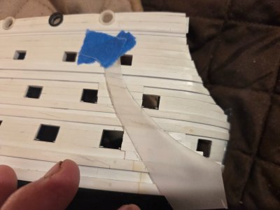
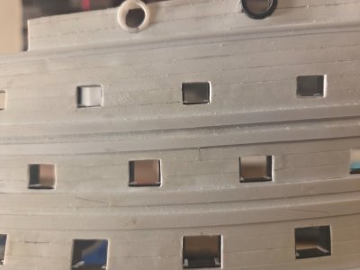
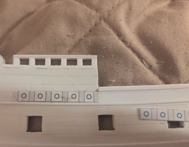
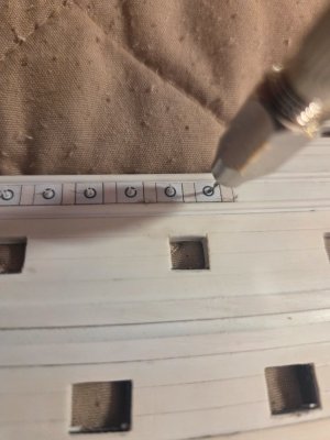
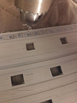
I decided to add the anchor linings. I created a template that I taped to the hull. I used more 0.5mm x 4.0mm planks, glueing three planks thogether and four planks together forming two small squares of planks that I placed in between the wales. I then used the template to pencil trace the curves onto the squares (glueing the planks together in advance meant I didn't have to trace and fit individual planks).

20260529_061005.jpg

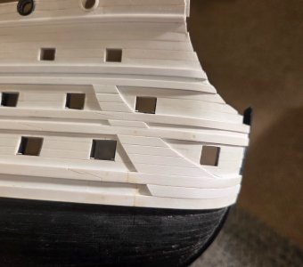
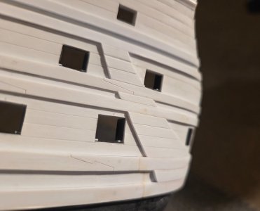
The anchor lining is substantially thicker than on SR1671.1, and that is because the wales protrude more from the hull. The lower wales protrude 1.5mm from the hull, the middle wales protrude 1.0mm from the hull, etc.

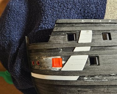
As I look at these photos, I am not liking the very wide plank seam at the first plank below the bottom upper wale. I am not sure why that appears to be so thick, but I will lightly sand and fill the gap, then use a Tamiya scribe tool to etch a thin line in.


20260529_093226.jpg

20260529_093238.jpg
 
Last edited:
It's a shame the MSW site crashed, for a whole host of reasons, but among them is the ability to look back at your early work, when you first decided to start upgrading the stock hull with things like skids, for example. The difference in scaling, attention to detail, and workmanship is literally night and day. It's as though this model has been a kind of apprenticeship into scratch-building, and you are now a journeyman.
 
It's a shame the MSW site crashed, for a whole host of reasons, but among them is the ability to look back at your early work, when you first decided to start upgrading the stock hull with things like skids, for example. The difference in scaling, attention to detail, and workmanship is literally night and day. It's as though this model has been a kind of apprenticeship into scratch-building, and you are now a journeyman.
Thank you, Marc. This is my third iteration, and it certainly has given me ample time to try and improve my skills! But the best teacher for me, has been poring over the magnificent build logs, whether on MSW or on this website!

My MSW build log may be gone, but I still have the pix... it shouldn't be too difficult to decide which photo is SR1671.0, and which one is SR1671.1!

20240131_073329.jpg20240205_170811.jpg
 
A milestone, of sorts... but there are many more to go. The inner hull planking and anchor linings are completed.

So, next on the list is to do the sills and stops for the Upper Gun Deck gun ports and the QD gun ports. I think I will leave the hull fenders/ladders for thr last step, as they are delicate. I need to drill a lot of holes around every gun port.... about seven holes for any gun port that has a lid. One hole for the lanyard for the lid, two holes for anchoring the lids to the hull (via fine wire), and four holes for gun carriage tackle.

I made jigs for SR1671.1 for these items, so perhaps they will carry over to SR1671.2.. otherwise it is simple to fabricate jigs.

Then... before the fender work begins, my thought process is to get all of the drilling and sanding and cleaning glue squeeze out and scribing touch ups and... ANYTHING that creates dust done and finished. Then I will give both hulls a bath in warm, soapy water and attach the fenders and ladders.

After that, I am thinking I am actually done with hull modifications!

EXCEPT.... as I think about it, since I will be fabbing the Quarter Galleries from scratch, I need to think how they will look and be anchored before I do any painting and glue the hull halves together. SR1671.2 started in December 2025... it's been almost six months to get to this point, and I really can't complain.

20260605_052514.jpg

20260605_052524.jpg

20260605_052430.jpg
 
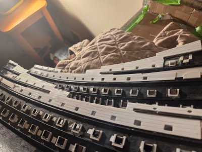
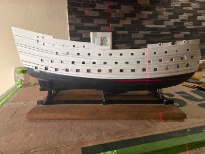
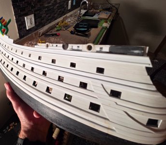
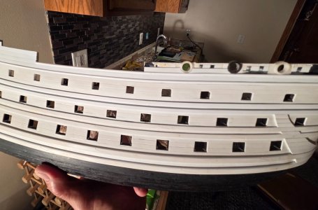
The "Kudin" gun port lid stops are installed (I don't know an official name, but I loved the appearance of the gun port stops that Kudin had on his Le Fleuron YouTube videos). a total of eighty broadside gun ports have these stops installed,

20260610_110350.jpg

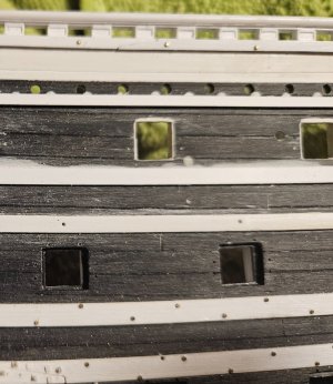
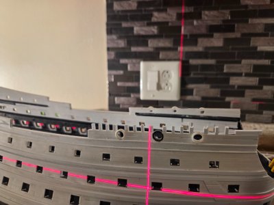
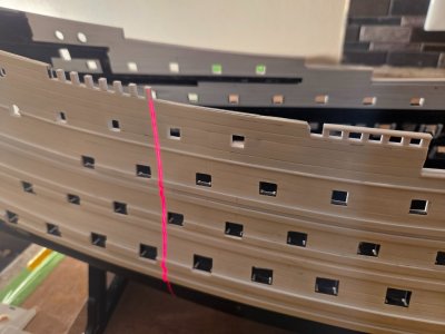
I rechecked every gun port with my laser. Now all that is left is some needle file work and fimal squaring and cleaning up - there is plenty of dust!

20260610_110502.jpg

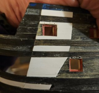
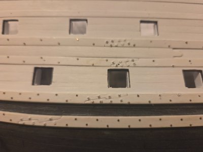
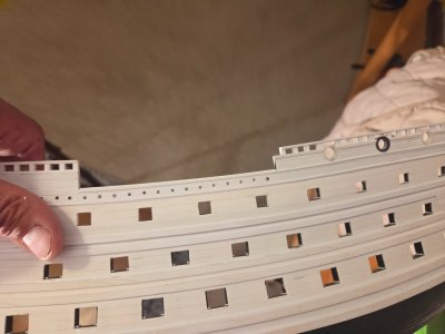
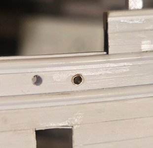
I think the next step is to start installing the timberheads and cap railings. When they are in place, I can mark each timberhead vertically with the laser, so that will guide my bolts. This photo is from SR1671.1. You will notice the through bolts at the scarf joints, following what Marc LaGuarda did... this involved cutting a very small square "washer", then attaching a domed rivet head on it (I sourced some very tiny domed rivet heads from a railroad supply store). And you can also see the bronze colored nail heads that I used to represent the regular bolts in the wales. These are tiny metal nails that I found online... the circular heads are 0.5mm in diameter, or 2" at scale (you will note that some of the gray bolt heads have fallen off - they are delicate and I attached them way too early in the process!).

Ohh... with the timberheads on, I can also cut the round fighting holes at the waist that were still prevalent at this time period - they allowed for pikes or guns or whatever to be thrust through in a need to repel boarders.

The final thing that I can think of is fabricating the three fenders and the side ladder.... those are delicate and the last thing that I want to affix on the hull when all else is completed.

20260610_110319.jpg
 
I have spent what ship time that I have had the last two weeks filing and sanding and getting every gun port to be as square and crisp as I can.

This time on SR1671.2, I have kept an Excel spreadsheet for every manner of specification and measurement that I have done up to this point. Unfortunately, some things like all of my SR1671.1timberhead measurements and spacing were in my MSW build log... so I have been trying to reverse engineeer some things!

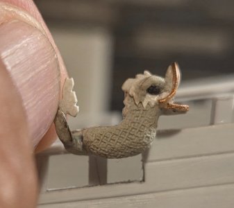
I have reached the point where I can start mass production... I had to make sure that my dolphin hance pieces would fit on the timberheads and cap railing... I did NOT want to have to recreate four dolphin hance pieces to a different size!

20260623_161807.jpg

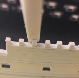
As seen on SR1671.1 below, the timberheads (except at the waist) will be 2.5mm tall (10" at scale), with a cap rail 1.5mm thick (6" at scale)resting on the timberheads. The timberheads will be 3.0mm wide after being framed on the sides with 0.25mm stock. Note that the horizontal framing is wider at 0.5mm' I suppose I will stick with that size again.

20241113_100437.jpg

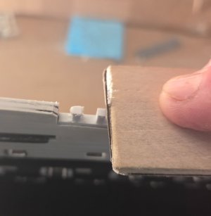
Again, as seen on SR1671.1, I will attach timberheads that are taller than the 2.5mm final height, say 4mm or so. You can see the actual pencil line that I drew on the timberheads for the final height, and it was way too much work to sand them from 7mm down to 2.5mm! However, adding some extra height before sanding to the proper height allows me to do a much better job of making sure that even as the sheer lines change, the timberheads are always perfectly vertical.

One thing that I will do on SR1671.2 that I was completely unware of before... I didn't realize that, while the timberheads viewed from the side are always perfectly vertical (requiring different cut angles on the bottom of each timberhead), when viewed fore to aft the timberheads follow the curve of the tumblehome. So where the bulwark meets the beakhead bulhead, the timberheads will actually flare outwards. Going further aft to the rear bulwarks, they will actually lean inwards to match the tumbehome.

20240730_095051.jpg

20240730_124117.jpg
 
Due to an extra three day delay in getting a bunch of Evergreen styrene strips delivered to me, I ended up with.. a "change of direction" (I've lost count). Or perhaps more like "scope creep"?

During that time, I communicated with Marc LaGuardia about timberheads and railings, especially on "Dutchy" ships in the 1660-70's. His ability to immediately provide pictures/drawings to illustrate his thoughts is amazing!

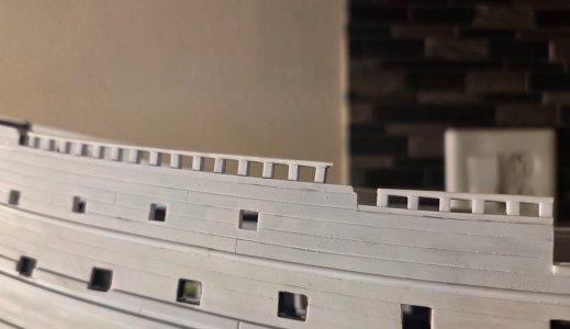
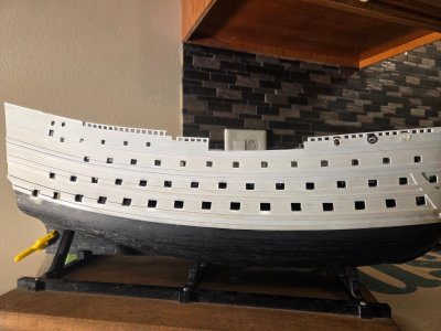
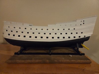
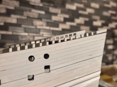
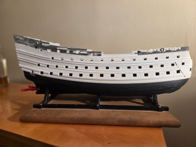
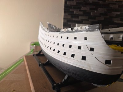
So, this is what SR1671.2 looks like now; what was the drift rail and all planking above have been stripped away for one reason.... raising the height at the waist by 1.5mm (already done in these pix) AND then repositioning the drift rail 1.5mm higher as well. The 1.5mm half-round was set on a 3.2mm wide strip - and all of the surrounding planks were 4.0mm wide. I couldn't have a 3.2mm wide plank ruining the view, so it was simply easier to remove the planks and replank again with all 4.0mm strips.
6566.jpg

6564.jpg

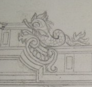
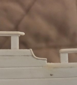
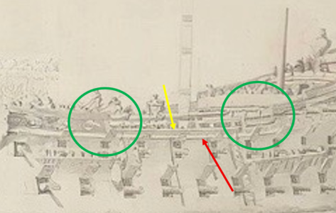
This VDV drawing of Royal Therese shows as well as any my goal after contemplating Marc's thoughts. RED arrow idicates the lower drift rail. Yellow arrow indicates the top drift rail/cap rail. The green circles highlight the fore and aft ends of the waist. The lower drift rail runs the length of the ship; the top drift rail terminates at the aft end of the waist, sort of combining with a J-shaped hance piece. NOT running this rail all of the way aft to the Quarter Gallery will give me more real estate for the rear bulwark frieze/decorations extolling the virtues of Louis XIV and the French State. I am on the fence if the top rail will run forward to the bow, as period drawings seem to indicate a mix of 1) running to the bow, and 2) terminating at the fore end of the waist with another J-shaped hance piece. On some drawings, it seems that running the drift rail forward to the bow would cut across the gun ports? If you look at SR1671.2, I have room enough that the top drift rail would rune forward and be below the circular gun ports. Plenty of room.

What this also meams is NO timberheads at the waist, as also shown by RT. I had been contemplating a design where I doubled the height of the waist timberheads to allow their cap rail to run seamlessly with the other rails. Those would be some pretty tall timberheads, almost three foot tall at scale,
Royal Therese.png

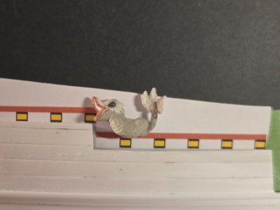
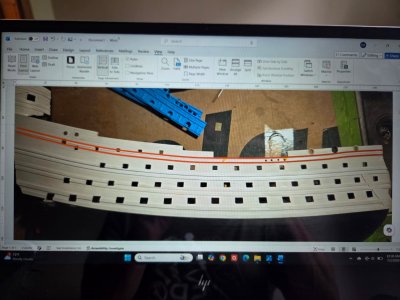
Finally, this bit of playing with Word gave me an idea to see what increasing the height at the waist and moving the drift rails up would do. Note that I added a few circular fighting holes at the waist and ran the top rail all of the way aft. This looks too congested to me, and also takes up a bit too much of the real estate. As noted earlier, the top rail will terminate at the aft end of the waist.

6567.jpg
 
Almost done with the starboard side, and liking this concept much better! The bottom drift rail runs for and aft the entire length of the ship, a 1.5mm half-round. The top drift rail, also 1.5mm half-round, is level with the waist (increased waist height by 1.5mm), and runs forward to the bow (but terminates at the aft end of the waist). I decided to run the top drift rail to the bow because I had room!

Now, the various other rails (on top of the timberheads, the rails at the base of the timberheads, etc) will be 1.0mm half-rounds... slightly smaller in diamter as I want the total thickness of the cap rails to be 1.5mm.

20260704_073839.jpg

20260704_112116.jpg

20260704_112129.jpg

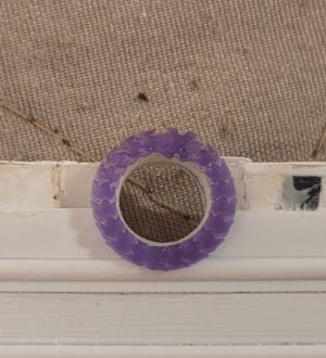
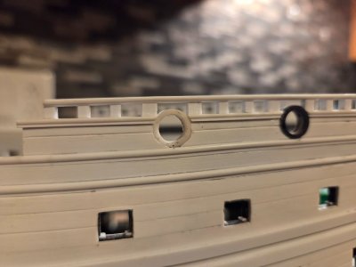
My circular gun port wreathes from Skutznik will fit just fine. I will have to notch a tiny bit from the drift rail in order for the wreath to fit flush.

20260704_112048.jpg
 
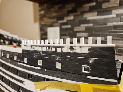
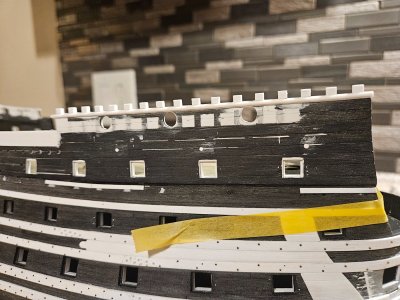
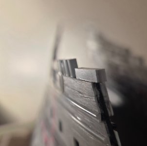
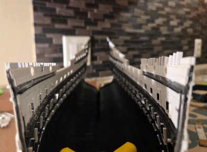
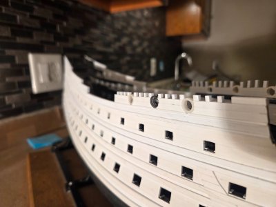
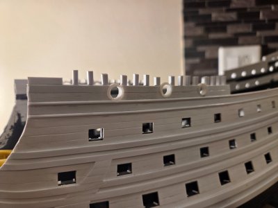
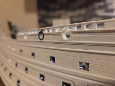
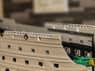
The starboard forecastle timberheads are in place. They are just shy of 5mm tall, but will be gently sanded down to 3.2mm. The extra initial height makes it easier to use the laser level to get precise vertical alignment. The spacing between timberheads is 5.0mm.
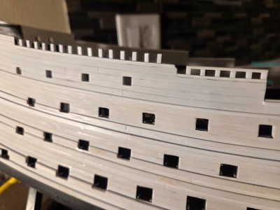
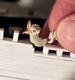
The timberheads are nominally 2.5mm x 2.5mm, but I made the "timberheads" (futtocks?) that bracket a circular gun port somewhat wider, 3.5mm wide. I have seen some drawings and pictures of models that make these specific wooden frames wider... perhaps for additional strength, especially for the gun tackle bolts?

20260706_173408.jpg

I am comfortable that I got the angles at the base of the timberheads correct, so that the timberheads follow the sweep of the tumblehome. This was fairly straightforward, using straight edges placed against the hull, The closeer you get to the bow, the more pronounced is the outward sweep.

20260706_173136.jpg
 
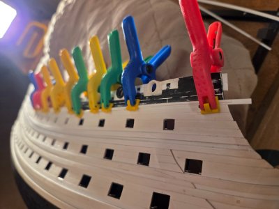
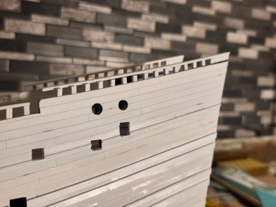
Both sides of the forecastle have timberheads in place. The starboard side has been sanded down to 3.2mm in height, while the port side timberheads have not been sanded yet, and are 5.0mm in height. 20260713_174916.jpg

I let the timberhead glue set overnight before I attempt any sanding. The next step will be to add the railings; as mentioned before the main drift rail below was a 1.5mm half-round. The timbehead railings will be 1.5mm thick with a 1.0mm half-round. Once the railings are in place, I will frame the timberheads with 0.5mm x 0.25mm strips.

20260713_172643.jpg

20260713_172625.jpg
 
Back
Top