Sovereign of the Seas, a reconstruction based on Sheldon O3 design

I have drawn a top view and a side view line of greatest breadth and combining these two create the 3d line of greatest breadth.

To do this I first draw horizontal lines in 3d view to the side view line of greatest breadth at the maximum breadth of 46,5 ft or 23,25 ft to both sides. You do this for every frame you want to draw. For me this is every 3rd frame.
View attachment 447051

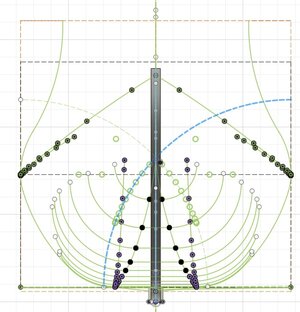
If this is done you switch to the top view and match the drawn horizontal lines to fit with the top view line of greatest breadth.
View attachment 447052

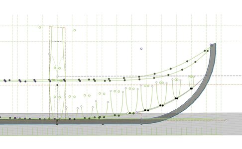
If this is done for all the lines and you switch to 3d view you see the shape already.
View attachment 447053

Now the ends of the vertical lines are connected with each other. I wanted to do that with arcs but fusion 360 doesn't want to do that in 3d, so I used straight lines, for creating my frames this is not an issue.
You now see the fwd line of greatest breadth.
View attachment 447054

For the aft the process is the same as can be seen below.
View attachment 447062
View attachment 447063
View attachment 447064

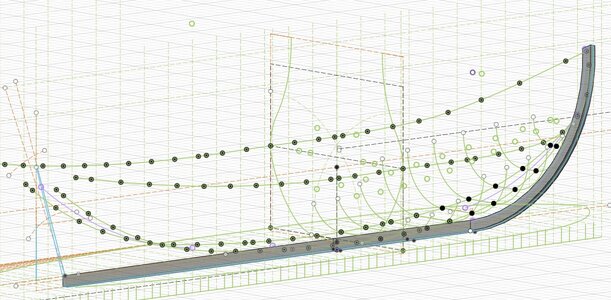
Resulting in a complete line of greatest breadth.
View attachment 447065

Next will be the line of the floor.
Nice to see the image growing. A deja-vu to ‘a while’ ago. But o o o, you lose too much if you haven't used it for a few months.;):(
I recognized the steep learning curve.:D
Send you a PM.
Regards, Peter
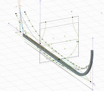
 
After the line of greatest breadth it is now time for the line of the floor.

But before starting with that I will give you an idea what the meaning of all these lines is.
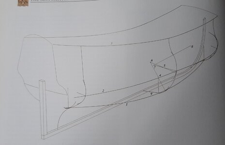
Ofcourse the line of greatest breadth is clear it shows the greatest breadth of the ship from bow to stern, but the line of the floor is different and the picture below from Richard Endsor's book is a great overview.
20240529_083850.jpg

At the bottom in this drawing you see the line of the floor, above that the line of greatest breadth and on top the sheer line.
With these three lines you can design the shape of the frame in every position in the ship, creating your hull. These give you the positions of the critical radii in the frame design.

The line of the floor determines the position of the arc between the floor of the frame towards the futtock starting with an horizontal tangent arc at the line of the floor, which I will show later when we come to frame design.

But first the rising line of the floor.
The rising line of the floor is starting at the center frame at the height of the top of the keel plus the deadrise.
Again I take the sheldon design here who created a line with two different radii forward and aft.
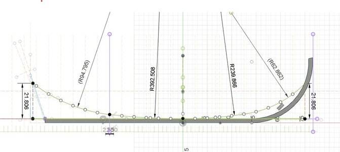
At the bow and at the stern the line crosses the bow or stern at the same height, being 7/6th x depth, or 7/6 x 19,333 = 21,806'.
The first tangent arc starting at the center frame going forward has a radius of 11 x height of the line fwd = 239,866 ". This radius is used untill half of the frames counted forward, in my case untill frame 16. The remainder is filled with a tangent arc to the first arc and crossing the height at the bow of 21,806'.
Aft it is the same except the first arc has a radius of 18 x height of the line aft = 392,508' and running towards the 18th frame.
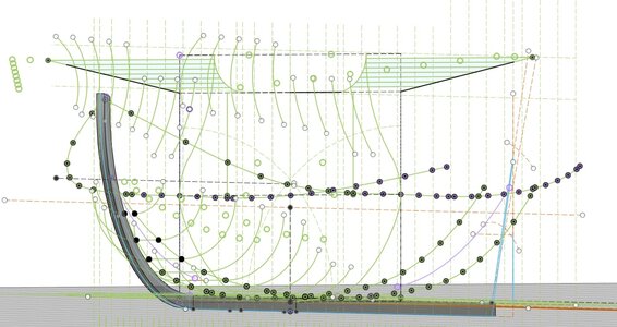
You can see the line forward and aft below, the rising line of the floor.
Rising line of the floor Sheldon.jpg

To create the 3d line we now need the top view, called the narrowing line of the floor. This consist on each side of a tangent arc starting at the center frame at the width of the floor, for SotS being 14", and ending in a single point at the bow. At the stern this is again a ratio from Sheldon being 3/13 x breadth or 3/13 x 46,5 = 10,73'
Rising line of the floor top Sheldon.jpg

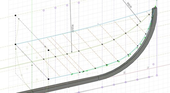
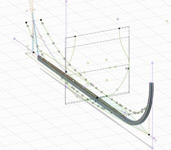
Now the rising line and the narrowing line of the floor are drawn these can be combined into a 3D line of the floor.
Rising line of the floor 3D Sheldon.jpg

Next will be the last line which is the sheer line showing the shape of the top of the ship.
 
After the line of greatest breadth it is now time for the line of the floor.

But before starting with that I will give you an idea what the meaning of all these lines is.
Ofcourse the line of greatest breadth is clear it shows the greatest breadth of the ship from bow to stern, but the line of the floor is different and the picture below from Richard Endsor's book is a great overview.
View attachment 450304

At the bottom in this drawing you see the line of the floor, above that the line of greatest breadth and on top the sheer line.
With these three lines you can design the shape of the frame in every position in the ship, creating your hull. These give you the positions of the critical radii in the frame design.

The line of the floor determines the position of the arc between the floor of the frame towards the futtock starting with an horizontal tangent arc at the line of the floor, which I will show later when we come to frame design.

But first the rising line of the floor.
The rising line of the floor is starting at the center frame at the height of the top of the keel plus the deadrise.
Again I take the sheldon design here who created a line with two different radii forward and aft.
At the bow and at the stern the line crosses the bow or stern at the same height, being 7/6th x depth, or 7/6 x 19,333 = 21,806'.
The first tangent arc starting at the center frame going forward has a radius of 11 x height of the line fwd = 239,866 ". This radius is used untill half of the frames counted forward, in my case untill frame 16. The remainder is filled with a tangent arc to the first arc and crossing the height at the bow of 21,806'.
Aft it is the same except the first arc has a radius of 18 x height of the line aft = 392,508' and running towards the 18th frame.
You can see the line forward and aft below, the rising line of the floor.
View attachment 450301

To create the 3d line we now need the top view, called the narrowing line of the floor. This consist on each side of a tangent arc starting at the center frame at the width of the floor, for SotS being 14", and ending in a single point at the bow. At the stern this is again a ratio from Sheldon being 3/13 x breadth or 3/13 x 46,5 = 10,73'
View attachment 450302

Now the rising line and the narrowing line of the floor are drawn these can be combined into a 3D line of the floor.
View attachment 450303

Next will be the last line which is the sheer line showing the shape of the top of the ship.
I'm impressed with your progress in Fusion, Maarten.
I placed 2 fingers on the last image to rotate it .......oops, it’s just a print ……..
Regards, Peter
 
Last edited:
To show you what the line of the floor actually does I will continue with the fwd part of the ship drawing the the floor sweep also called the sweep at the rung head.

The rising line of the floor is rising the horizontal lower part of the frame. The narrowing line of the floor is shortening this horizontal frame part.
You can see this in the picture below where we ended last time, the 3D combined Rising and narrowing line.
Rising line of the floor 3D Sheldon.jpg

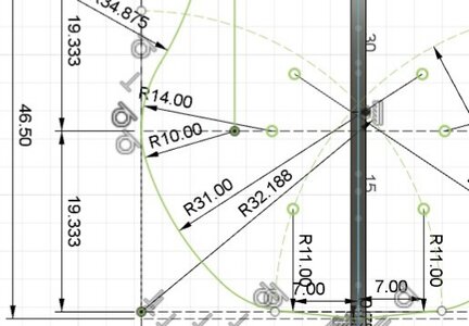
The floor sweep is tangent to the horizontal line of the floor. The radius of the floor in the FWD part of the Sheldon design hull is variable and the centre of the Radius of each frame is positioned on an arc with its centre on the lower corners of the design grid and running through the centre point of the centre frame floor sweep.
Here it has a radius of 32,188' and going through the floor radius centre of 11'.
toptimber sweeps FWD Sheldon.jpg

Below you see all floor sweeps drawn with their centre points on the blue line for the SB side.
FWD view Floors FWD Sheldon.jpg

If we look from the side you clearly see what happens to the shape of the hull, it raises and narrows the frames and makes the frames more slender towards the bow creating a sleek hull.
The horizontal floors drawn are purely design (imaginary) and not directly part of the construction.
Floors FWD Sheldon 2.jpg

But you do see the lower frame shape starting to evolve.
Floors FWD Sheldon.jpg

Next time further frame design.
 
Maarten,

Superlative amount of research - Big kudos to you!!!
Thx for the kudos glad you like it, as I do like your SotS build.
I am implementing the research that was done by Waldemar on the O3 model and apply it on the data we have on the SotS to see if I can devellop a proper hull design on for the SotS.
 
To show you what the line of the floor actually does I will continue with the fwd part of the ship drawing the the floor sweep also called the sweep at the rung head.

The rising line of the floor is rising the horizontal lower part of the frame. The narrowing line of the floor is shortening this horizontal frame part.
You can see this in the picture below where we ended last time, the 3D combined Rising and narrowing line.
View attachment 454159

The floor sweep is tangent to the horizontal line of the floor. The radius of the floor in the FWD part of the Sheldon design hull is variable and the centre of the Radius of each frame is positioned on an arc with its centre on the lower corners of the design grid and running through the centre point of the centre frame floor sweep.
Here it has a radius of 32,188' and going through the floor radius centre of 11'.
View attachment 454160

Below you see all floor sweeps drawn with their centre points on the blue line for the SB side.
View attachment 454161

If we look from the side you clearly see what happens to the shape of the hull, it raises and narrows the frames and makes the frames more slender towards the bow creating a sleek hull.
The horizontal floors drawn are purely design (imaginary) and not directly part of the construction.
View attachment 454162

But you do see the lower frame shape starting to evolve.
View attachment 454163

Next time further frame design.
You made some nice steps in the design, Maarten. And by the rotation of the 3D model she starts to show her lines.
Regards, Peter
 
Huge thank you to Maarten and EVERYONE who contributed to this thread. The information provided is so very valuable to any modelers taking on building HMS Sovereign of the Seas!
Hi Kurt,
Always good to see fellow SotS enthousiast. Together we can maybe get closer to the real design of the ship.
 
Hi Jim,
As a great philosopher onces said:
I have never done it before so I think that I can do it (Pipi Langstrump) :cool:
it is too late for me to be a philosopher, maybe in my next life. Gosh...I already have so many things to do for my next life, I am afraid one will not be enough... ;) ROTFROTFROTF
 
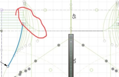
The next step in the frame design is the sweep above the breadth. It starts at every frame vertical from the maximum breadth line.
For the the O3 model (as analysed by @-Waldemar- ) there is a variable radius for these sweeps towards the fwd side of the ship.
I use the same proportions here as for the O3 model of Sheldon except I base my actual radous on the provided data by Phineas Pett for this sweep being 14'.
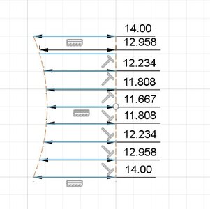
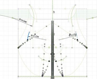
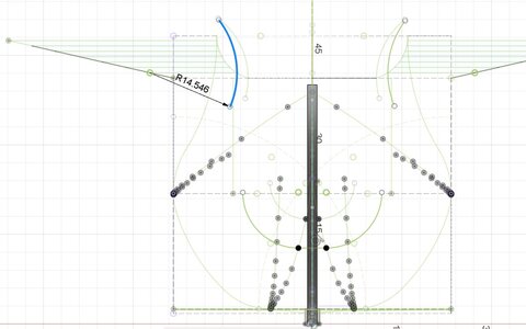
The radius decreases towards 11 2/3' over the number of frames fwd and than increases again towards a radius of 14'. I have 9 drawn frame stations between the center frames and most fwd frame over which I spread the fluctuation of the radius and determine the individual radii in the drawing below.
Reducing device upper breadth radii FWD.jpg

Now at the respective frame positions I can drawn the curve starting vertically from the line of greatest breadth.
Below you see the example of the 3rd frame from Fwd.
Upper Breadth sweeps FWD Sheldon.jpg

This you need to do for all other drawn frames also with their respective radii.

The top timber hollowing sweep you see on top I will discuss next time.
 
Last edited:
On to the fwd top timber hollowing sweep.
The length of the radius is a rather complex one and is variable and therefore different for every drawn frame.
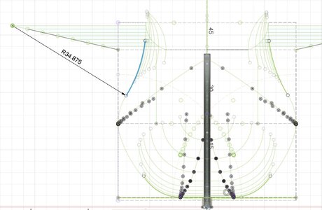
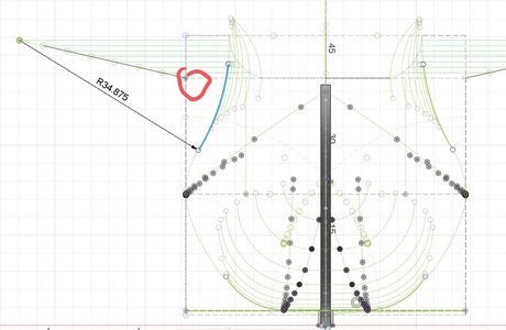
To create the radii we start with the center point of the centre frame. The radius for this centre frame top timber hollowing sweep is 34,875' which is 3/4 x breadth = 3/4 x 46,5'.
toptimber sweeps FWD 3 Sheldon.jpg
The same curve applies to all frame where the maximum breadth line is the same thus until frame number 6 FWD. On the remainder of the drawn frames FWD the radius changes.
The centre point of the radius for these frames is determined by drawing a straight line between the centre frame radius centre towards the double depth (here two times 2 x 19,333') corner of the design grid.
toptimber sweeps FWD 3 Sheldon.jpg
Now this line is devided in 7 equal parts, every dot is now representing the centre point for the radius of the next fwd frame being frames 9, 12, 15, 18, 21, 24 and 27.

The length of the radius is determined by a second curve which is drawn tangent from centre frame design grid top timber width towards the lower breadth of the fwd bulk head.

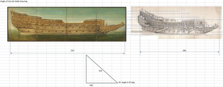
The FWD bulkhead breadth I have taken from two angled Van de Velde drawings, the first at 46 deg and the second at 10 deg. And yes in between these two drawings many modifications have been done to the ship.
Van de velde angle.jpg

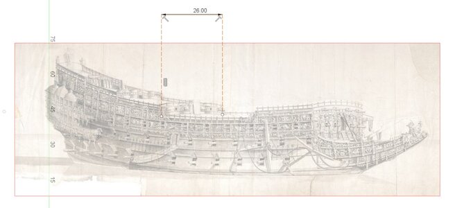
Below the measurement on the centre bulkhead for which I used the same methode.
Top timber width van de Velde.jpg

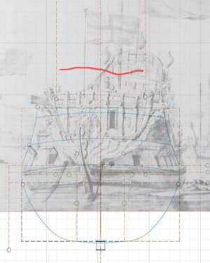
And the later fwd bulkhead after the last rebuild with still the same statues width the measured breadth marked by the red line.
center frame reconstruction van de Velde last rebuild with Newton max top timber.jpg

This fwd bulkhead breadth is set at the bottom of this arc.
toptimber sweeps FWD 3 Sheldon.jpg

Now the dots on the straight line determine the centre point of the radius and the end on the arc the length of the radius. Now all 7 sweeps can be drawn. Below showing the sweep of frame 24 fwd highlighted.
toptimber sweeps FWD 2 Sheldon.jpg

After drawing all top timber hollowing sweeps FWD on PS and SB the 3D already starts to look like a ships hull. If it is close to the shape of SotS we will see when comparing the finall designed hull to the contemporary drawings.
toptimber sweeps FWD 4 Sheldon.jpg

Next time we connect the above maximum breadth sweep to the toptimber hollowing sweep.
 
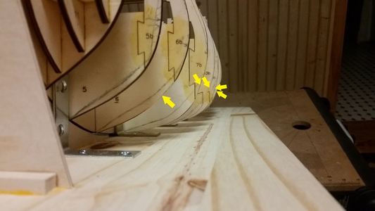
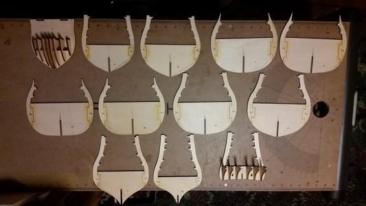
Early in construction, the frames of my model were modified in an attempt to make the hull shape following the curves Maarten and others are determining using a far more detailed study. At least the model was made a bit closer to the hull form described in such exquisite detail using conventional 17th century methods in this thread. The original frame outlines were too full in shape at the first and second futtocks. My sincere admiration and gratitude for you fellow who are attempting to put this ship design puzzle together and arrive and a best guess at how the Sovereign was built.
1719997242028.png

Original frame shapes.
1719997648953.png
 
Last edited:
Back
Top