- Joined
- Apr 4, 2023
- Messages
- 5
- Points
- 13

Hi everyone!
I have various questions. I'm going to explain shortly.
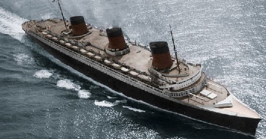
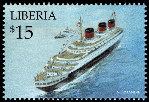
1.-I have a navy plan's for SS Normandie(1935), but they have a quite distorsion, how can I keep it out? I have been working with photoshop and with the tool(deformación de posición libre), I don´t know the English name, something like: free tool of deformation, I think. The problem is that maybe this tool is quite freehand.
2.-How can I translate the information of plating plan into a 2D profile view of Normandie? I think that the lenght of the steel sheet is easy because I only need to count couples in the keel, but how can I know the real vertically lenght?
Kind Regards from Spain
Iván.
I have various questions. I'm going to explain shortly.
1.-I have a navy plan's for SS Normandie(1935), but they have a quite distorsion, how can I keep it out? I have been working with photoshop and with the tool(deformación de posición libre), I don´t know the English name, something like: free tool of deformation, I think. The problem is that maybe this tool is quite freehand.
2.-How can I translate the information of plating plan into a 2D profile view of Normandie? I think that the lenght of the steel sheet is easy because I only need to count couples in the keel, but how can I know the real vertically lenght?
Kind Regards from Spain
Iván.