Really nice work, stuglo!
-

Win a Free Custom Engraved Brass Coin!!!
As a way to introduce our brass coins to the community, we will raffle off a free coin during the month of August. Follow link ABOVE for instructions for entering.
You are using an out of date browser. It may not display this or other websites correctly.
You should upgrade or use an alternative browser.
You should upgrade or use an alternative browser.
Upper Deck cont.
TFFM suggests that these beams may not have been let down. Seems strange to me, but given the heights of my clamps, I don’t need to.
The Carlings are generally 3.45mm wide and 2.65mm deep.( hatch covers eg are 3.84x3.18)
The Ledges are (also with exceptions) 1.86mm wide and 1.6mm deep.
The Hanging Knees (present on all beams) 3.45mm wide and shaped similarly to those of the lower deck- but varied according to hull shape.”Beam” arm 21.2mm.Hanging arm, 28.6mm.
The Lodging Knees are 3.18mm wide, beam arm, 23.85mm and hull arm length determined by distance between adjacent beams. Aft end is notched to allow the Hanging Knee to fit against the hull.
Non-glued corners are chamfered.
Beam #2
Fore- there are 2 pairs of Carlings angled towards the Hull. Some trimming of the bulkheads is necessary.
Between #2 Beam and #3 Beam, there are a pair of Carlings.(part of the Fore Mast Partners structure) 4.24mmX2.65mm deep, and set 12.72mm apart.
These Carlings are Half Joined (recessed) under the beams #2 and#3, so that they sit with the upper surface 0.53mm below the surface of the beams.
As the Beam thickness is 3.71, leaving the required 0.53mm will require mortissing of the ends of the Carlings as well.
I milled off 1.71mm from the underside of the beams, and 1.47mm from the ends of the Carlings
(The construction of the Fore Mast Partners are somewhat complex and only understood by reference to the 3D rendition).
The various mortisses are milled before fixing: slightly narrower than necessary, so that some final alignment can be accommodated,with a chisel scalpel.
I then fitted the Beam, made the lodging Knees from their pattern, with their mortisses, and fitted them. Then used the general pattern for the Hanging Knees, fitted and fixed.
Finally, Carlings and the various Ledges.(The outer ledges are wider than usual-I made them at 3mm.).
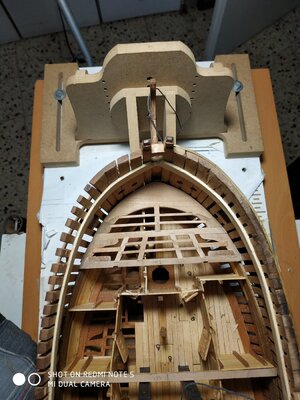

Kurt Konrath
Kurt Konrath
Your wood artwork is looking very nice, give a nice pleasant change in tone.
Kurt Konrath
Kurt Konrath
What is the REDMI NOTE 5 MI dual camera listing in your photos.
It is getting very nice clear and sharp depth of focus and images stand out will.
It is getting very nice clear and sharp depth of focus and images stand out will.
A cheap 3year old Chinese smartphoneWhat is the REDMI NOTE 5 MI dual camera listing in your photos.
It is getting very nice clear and sharp depth of focus and images stand out will.
Carlings and Fore Mast Partners Revisited.
My previous was incorrect-my understanding faulty, The 3D rendering is good but lacks measurements. My geriatric dyslexia required (again) a brainwave on awakening at 3 am and attending to the problem. (Unfortunately, the Bosun objects to my use of anything other than a pencil and paper-definitely no actual building at this hour.)
Anyway, the problem is the relationships between the Carlings, the Beams and the Chocks.
Most of the information is there (TFFM) spread over several pages.
(I will use the actual “inches” rather than the metric
scale for simplicity.)
Firstly, the the Carlings are 10in deep.The ends sit under the beams #2and#3, forming a Half Joint.
The Beam (7ins deep)is scored-undercut, by 4 ins.
The Carling is mortised,so as to leave its lower surface 1in below the lower surface of the beam- That means 5ins removed. Also it means that the upper surface of the Carling is 1in below the upper surface of the beam.
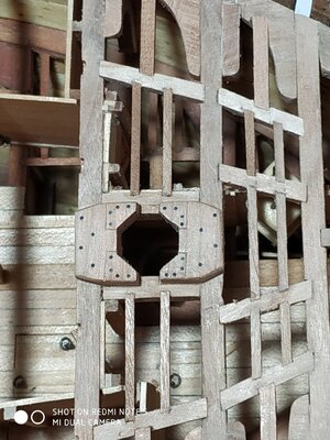
The Chocks, a pair fore and aft, sit on the Beams and the Carlings.(The Chocks are formed by a large Cross Chuck and a smaller Corner Chuck. Together they form a horseshoe shape. For simplicity, I made them as one piece.
The Chocks are nominally 10in thick and let down on the beam so a depth of 6 ins are proud, i.e. 4in removed.
They also sit on the inner aspect of the Carlings. These are let down by 3ins (4in-1in).
As there is a gap between the arms of the fore and aft pair of corner Chocks, this area is NOT let down, leaving the full height of the carling, between them. The outer (hull) side also remains at full depth-leaving a pattern like a “T” with a short “leg”.
Only NOW I begin to be able to interpret the drawings in TFFM
To be honest, it was only later that I realised this,after the Chocks were fitted. I therefore “faked” it by adding this”T”. Couldn’t face another remake. I’ll do it properly for the other Mast Partners.
Note- as these Carlings sit lower, the ledges are left 1in proud.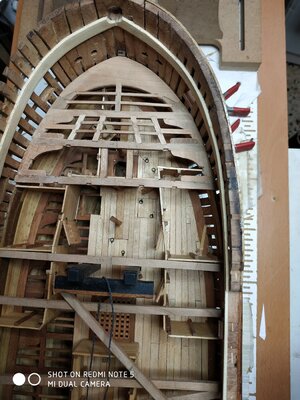
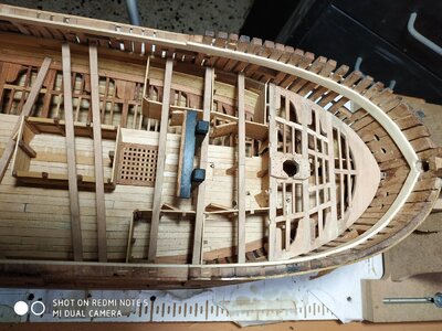


Last edited by a moderator:
Looks good, stuglo. Keep going!
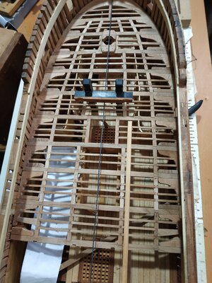
Upper Deck (cont.) Beams #5 to #10.
(Paper strip to cover open lower deck to prevent bits dropping through)
#5 The Beam sits in the mortises of the Riding Bitt Pin .
Bulkhead walls removed and adapted to allow for the hanging knee.
#6 and #7. Have the forehatch and therefore inner carlings closer together and without ledges.
#8 and #9. Regular features
#10. Aft, the mortise for the inboard Carling is not in line with those fore and aft , in order to form the support for the Main Hatch
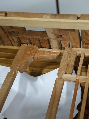
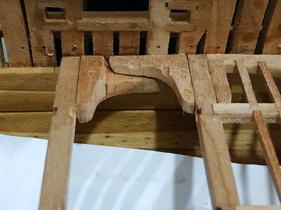
At the hull, fore to the beam, the normal arrangement changes to Opposed Lodging Knees ( similar to lower deck ). The aft of the pair sits beneath its partner and is fixed first. It is Let Down on the Clamp, to allow this.
The aft ledge is mortised into the upper Knee, about midpoint between the Beams. It is wedge shaped, the narrower end toward the Knee.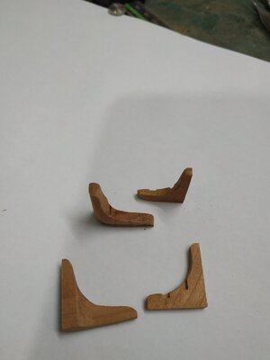
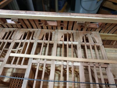


Last edited by a moderator:
- Joined
- Apr 20, 2020
- Messages
- 6,186
- Points
- 738

wonderful work, well done Dear friendUpper Deck (cont.) Beams #5 to #10.
(Paper strip to cover open lower deck to prevent bits dropping through)
#5 The Beam sits in the mortises of the Riding Bitt Pin .
Bulkhead walls removed and adapted to allow for the hanging knee.
#6 and #7. Have the forehatch and therefore inner carlings closer together and without ledges.
#8 and #9. Regular features
#10. Aft, the mortise for the inboard Carling is not in line with those fore and aft , in order to form the support for the Main Hatch
At the hull, fore to the beam, the normal arrangement changes to Opposed Lodging Knees ( similar to lower deck ). The aft of the pair sits beneath its partner and is fixed first. It is Let Down on the Clamp, to allow this.
The aft ledge is mortised into the upper Knee, about midpoint between the Beams. It is wedge shaped, the narrower end toward the Knee.
I am really impressed by the last picture. All those carlings and ledges so straight and true. Very nice. Hard to do.
Upper Deck (cont.) #11
A wider gap between Beam with special structures (as lower deck).
Firstly the Beam Arms. TFFM mentions that the Vulture has a paired arrangement and a triangular mast partner. My Atalanta plans show a similar arrangement, with what seems to be an overwrite on an erased area. This arrangement (like wings) is appealing to the eye, but I lack detail for the modified Main Mast Partner, so will go with TFFM plans.
The Beam Arms, are 3.71mm thick, and are tabled 0.8mm into #11 Beam.
The position of the fore inner and outer carlings similarly marked and checked that they line up with the carlings already fitted to foreward beams.
The position of the Tabling notches are taken from the plan and marked, with reference to the inner Carling. Note the symmetry-teeth and gaps 5.83mm
The aft outer Carling is inline, but the inner Carling is nearer the centre line, just outside the Pump Tubes.
The Beam is turned over and the position of the Mast Partner Carlings marked so that they are 14.84mm apart. These Carlings are 6.36mm wide and 5.3mm deep. The Beam is undercut by 2.12 mm deep and 6.36mm wide.
The various mortises and notches are milled
Before fixing, I made the Partner Carlings-(6.36x5.3) with a mortise of 2.65mm to Half Joint to the Beam, leaving its level 0.53mm below the Beam.
This was fortunate because I found that the upper lourve planks need trimming back.
This done, The Beam is fixed.(note it sits on the fore and aft walls of pump room and there is no pillar)
The Beam Arm is made with the cut-out TFFM pattern- the “teeth” position checked by offering up to the Beam. The outer arm trimmed to fit against the hull.
The inner Carlin is dry fitted and the inner end of the Beam Arm is trimmed to fit.
The Lodging Knee can now be cut to size, mortise for ledge marked and milled, and the part glued in place.
While still dry fitted, the positions of Carlings and Ledges are marked. These are milled and the Beam Arm glued in place.
The Hanging Knee, against the #10 Beam is made and fitted.
An Iron lodging Knee, 2mm wide is made from a leather strip, attaching the Beam Arm to the Hull.
A Packing Piece, 3.18 wide aX 1.6mmdeep, sits over the hull arm of the Iron, filling the gap between the Beam Arm and Hanging Knee.
The Outer Carling is divided by the Beam Arm, dry fitted, ledges aligned, marked and milled before fixing.
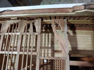
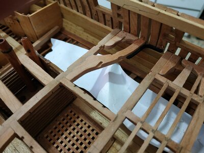
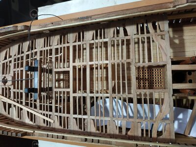


very good work - very good 
Looks very good. Very nicely done.
- Joined
- Oct 17, 2020
- Messages
- 1,687
- Points
- 488

Buongiorno, scusa che modello è ? Non mi riesce a leggerlo, GrazieUpper Deck (cont.) #11
A wider gap between Beam with special structures (as lower deck).
Firstly the Beam Arms. TFFM mentions that the Vulture has a paired arrangement and a triangular mast partner. My Atalanta plans show a similar arrangement, with what seems to be an overwrite on an erased area. This arrangement (like wings) is appealing to the eye, but I lack detail for the modified Main Mast Partner, so will go with TFFM plans.
The Beam Arms, are 3.71mm thick, and are tabled 0.8mm into #11 Beam.
The position of the fore inner and outer carlings similarly marked and checked that they line up with the carlings already fitted to foreward beams.
The position of the Tabling notches are taken from the plan and marked, with reference to the inner Carling. Note the symmetry-teeth and gaps 5.83mm
The aft outer Carling is inline, but the inner Carling is nearer the centre line, just outside the Pump Tubes.
The Beam is turned over and the position of the Mast Partner Carlings marked so that they are 14.84mm apart. These Carlings are 6.36mm wide and 5.3mm deep. The Beam is undercut by 2.12 mm deep and 6.36mm wide.
The various mortises and notches are milled
Before fixing, I made the Partner Carlings-(6.36x5.3) with a mortise of 2.65mm to Half Joint to the Beam, leaving its level 0.53mm below the Beam.
This was fortunate because I found that the upper lourve planks need trimming back.
This done, The Beam is fixed.(note it sits on the fore and aft walls of pump room and there is no pillar)
The Beam Arm is made with the cut-out TFFM pattern- the “teeth” position checked by offering up to the Beam. The outer arm trimmed to fit against the hull.
The inner Carlin is dry fitted and the inner end of the Beam Arm is trimmed to fit.
The Lodging Knee can now be cut to size, mortise for ledge marked and milled, and the part glued in place.
While still dry fitted, the positions of Carlings and Ledges are marked. These are milled and the Beam Arm glued in place.
The Hanging Knee, against the #10 Beam is made and fitted.
An Iron lodging Knee, 2mm wide is made from a leather strip, attaching the Beam Arm to the Hull.
A Packing Piece, 3.18 wide aX 1.6mmdeep, sits over the hull arm of the Iron, filling the gap between the Beam Arm and Hanging Knee.
L'Outer Carling è diviso dal Beam Arm, montato a secco, sporgenze allineate, contrassegnate e fresate prima del fissaggio.
View attachment 285259View attachment 285260View attachment 285259View attachment 285260View attachment 285266
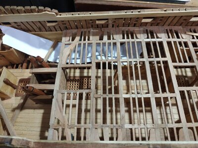
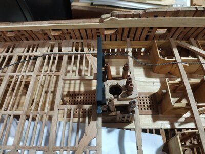
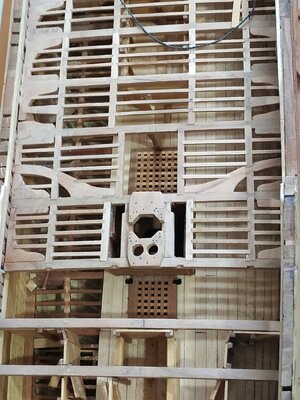
Upper Deck - Main Mast Partner
Similar to foremart counterpart.
The Carlings (6.36mm x 5.3mm deep) have already been made.
They are set 14.84mm apart. The fore outer aspect needs trimming to allow for the Pins of the Main Topsail Bitt.
The Carlings are half joined to #12 Beam which is cut underside by 2.12mm.
The upper surface of the Carlings are partially recessed to allow the Mast Partner to sit on the beam after being let down by 2.12mm. The depth removed is 1.59mm (2.12-0.53) following the “footprint” of the Partners.
The octagonal opening for the Pumps are filed out-but became more round than intended.
NOTE -Hanging Knees, after #10 Beam, are now placed FORE between beams
Also note that there are 4 ledges in outer group, and 5 for inner group.


It only gets better and better
Scusa, non ho capito. È un tipo Swan che utilizza libri TFFM e principalmente piani Altalantascusa che modello è ? Non mi riesce a leggerlo, Grazie
- Joined
- Oct 17, 2020
- Messages
- 1,687
- Points
- 488

Hi Stullo I don't know Altalanta plans, could you post some pictures? ThanksScusa, non ho capito. È un tipo Swan che utilizza libri TFFM e principalmente piani Altalanta


