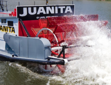
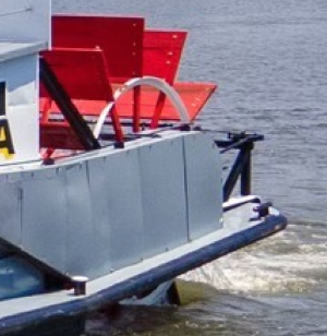
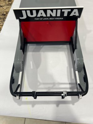
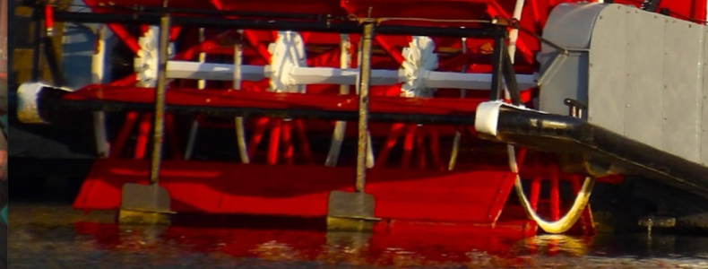
Looking forward to seeing how you progress with your build. I am sure I will learn what I need to know about getting it all set up. Gotta get a barge kit when they come out.
-

Win a Free Custom Engraved Brass Coin!!!
As a way to introduce our brass coins to the community, we will raffle off a free coin during the month of August. Follow link ABOVE for instructions for entering.
-

PRE-ORDER SHIPS IN SCALE TODAY!
The beloved Ships in Scale Magazine is back and charting a new course for 2026!
Discover new skills, new techniques, and new inspirations in every issue.
NOTE THAT OUR FIRST ISSUE WILL BE JAN/FEB 2026
You are using an out of date browser. It may not display this or other websites correctly.
You should upgrade or use an alternative browser.
You should upgrade or use an alternative browser.
I haven't post anymore pictures because Im assembling lots of small details, here is one of them, "The monkey rudders linkage".
I first will show a bunch of small parts with its corresponding ID, since there are not included with the instructions.
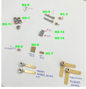
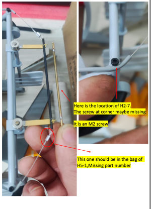
Im going to start with H2-7. Double holes tiny brass part.
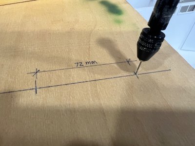
First you have to create a soldering jig like this;
Next you add the double holes H2-7 add two of the brass wire provided with the kit and also cut down to size the middle brass rood.
Glue down a strip wood to make the linkage straight.
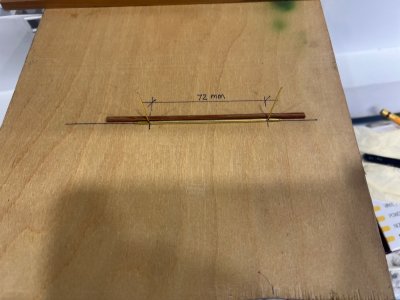
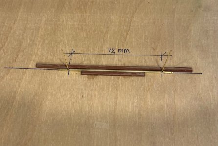
Ready to solder.
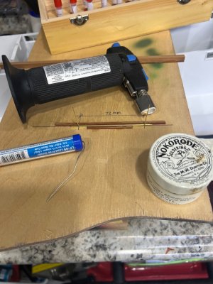
Final product.
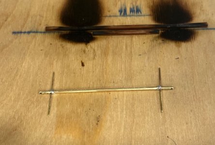
This is how it will go into the monkey rudders stand.
I first will show a bunch of small parts with its corresponding ID, since there are not included with the instructions.

Im going to start with H2-7. Double holes tiny brass part.
First you have to create a soldering jig like this;

Next you add the double holes H2-7 add two of the brass wire provided with the kit and also cut down to size the middle brass rood.
Glue down a strip wood to make the linkage straight.


Ready to solder.

Final product.

This is how it will go into the monkey rudders stand.

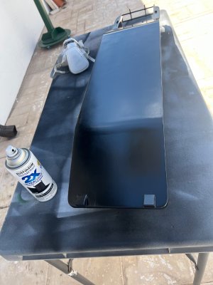
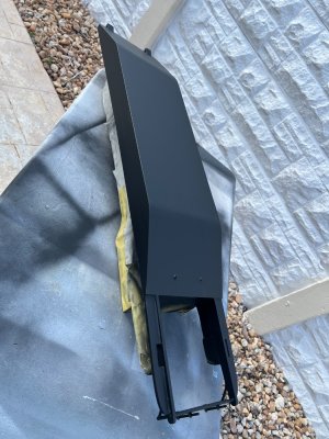
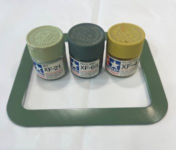
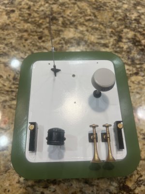
Other thing that I was working at the same time was to paint the pilothouse roof viser.
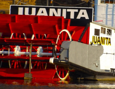
To obtain the greenish color that i could see in the real Juanita, I mixed these Tamiya colors.
XF-65 70%, XF-4 15% and XF-21 15%.
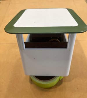
The pilot house roof gets lots of details like this.
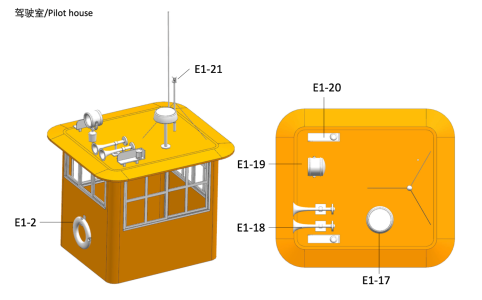
This is how I used the soldering jig included in the kit to create the roof towing light.
I started by adding a wider tube to serve as a soldering point for the legs to rest on, and glue some tabs to make it straight.
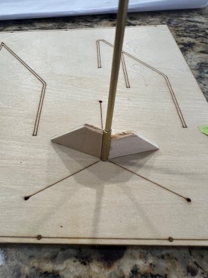
Then I slightly bent the part of the legs that will be inserted on the roof and place them on top of the resting tube like this.
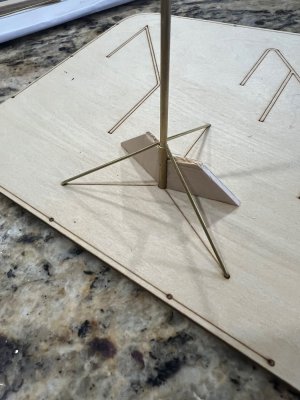
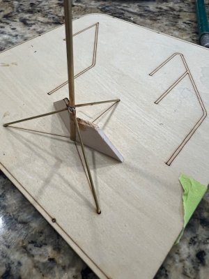
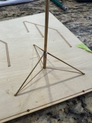
I cleaned the blob of solder, added the top light and proceed to paint it.
Notice that I have a protruding stub at the bottom so it could go into the roof hole.
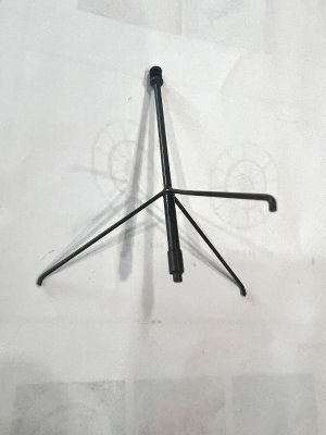
I just find ou that te germ bulb Im using is too big for this. I have to think now what to do.
Wile I give that some thought, I added the horns, navigation lights, radar and antenna.
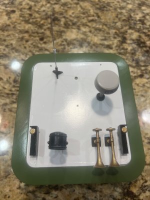
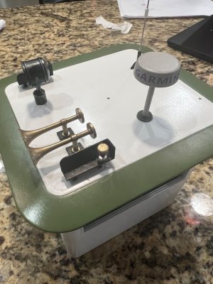
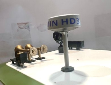
To obtain the greenish color that i could see in the real Juanita, I mixed these Tamiya colors.
XF-65 70%, XF-4 15% and XF-21 15%.


The pilot house roof gets lots of details like this.

This is how I used the soldering jig included in the kit to create the roof towing light.
I started by adding a wider tube to serve as a soldering point for the legs to rest on, and glue some tabs to make it straight.

Then I slightly bent the part of the legs that will be inserted on the roof and place them on top of the resting tube like this.


I cleaned the blob of solder, added the top light and proceed to paint it.
Notice that I have a protruding stub at the bottom so it could go into the roof hole.

I just find ou that te germ bulb Im using is too big for this. I have to think now what to do.
Wile I give that some thought, I added the horns, navigation lights, radar and antenna.


Other parts that Im working on are the stern wheel.
Lots of tedious work here.
It took me four hours just to tape them.
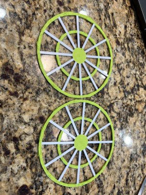
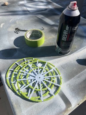
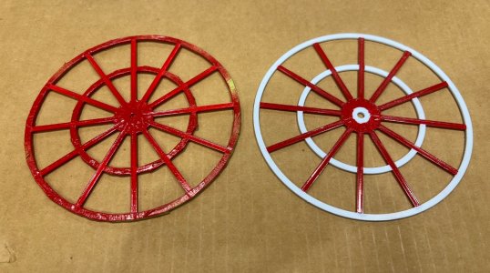
After the paint has dried you have to add more pieces to it.
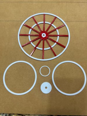
I scratched some of the paint where the middle ring will be glued.
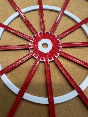
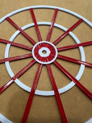
Now you need to add two more middle rings, one on each side of the wheels.
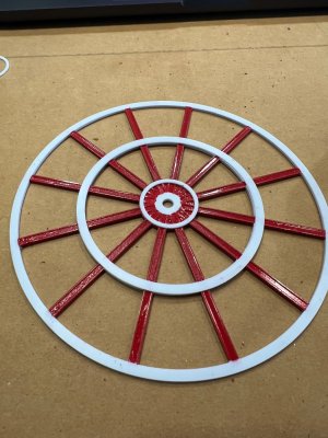
And finally, add the small center rounded pieces.
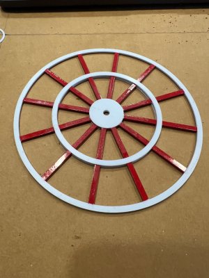
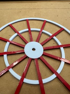
Lots of tedious work here.
It took me four hours just to tape them.


After the paint has dried you have to add more pieces to it.

I scratched some of the paint where the middle ring will be glued.


Now you need to add two more middle rings, one on each side of the wheels.

And finally, add the small center rounded pieces.


Last edited:
Excellent information on your build. Looks great!
This next part is for the "Pilot House entrance stairs".
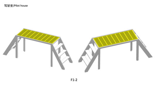
This are the parts.
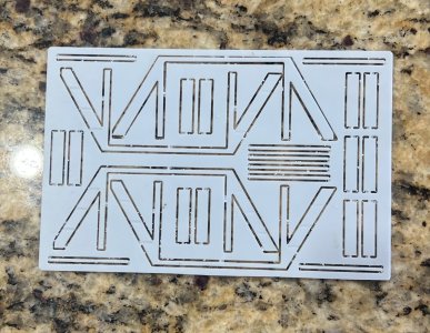
To add the steps to the sides, I first tape them down just to make sure that is not going to move wile I glue the steps down.
Use a small squared wood scrap so all the steps will come out square to perfectly match the other side.
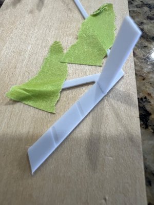
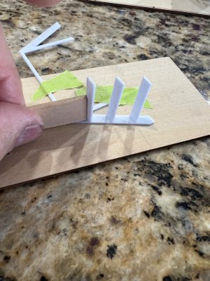
All steps added.
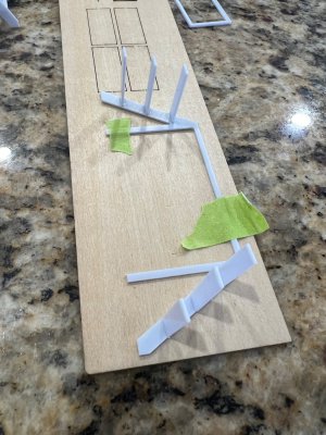
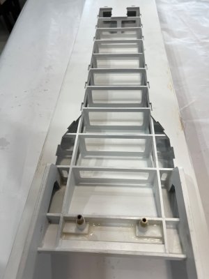
After this you will have to add a very thin piece of plastic to the inside of the stairs stand.
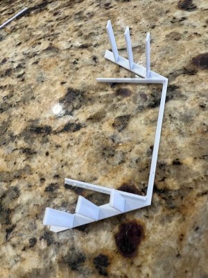
Add the other side, prime, pain and add the top grill. (metallic silver).
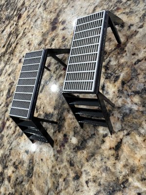

This are the parts.

To add the steps to the sides, I first tape them down just to make sure that is not going to move wile I glue the steps down.
Use a small squared wood scrap so all the steps will come out square to perfectly match the other side.


All steps added.

After this you will have to add a very thin piece of plastic to the inside of the stairs stand.

Add the other side, prime, pain and add the top grill. (metallic silver).

Fantastic build and project. Watching this. Lovely clean precise work.
Nailm:Fantastic build and project. Watching this. Lovely clean precise work.
You are so correct. Some times I go to my stash and start selling it on Ebay just to buy some more.
Crazy.
Another small step, "The Pilot roof navigation light".
Previously I showed how I soldered this piece but I just couldn't accept it. Something about it that I didn't like, it looked too bulky so I made another one, but this time instead of brass wire I used stringing wire purchased from Hobby lobby.
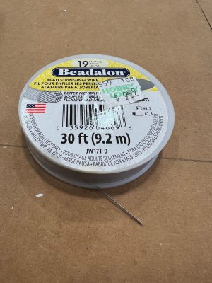
I wanted to use a clear brass light housing that I had purchased from Harbour Models and for that, I had to recreate the entire light pole like this.


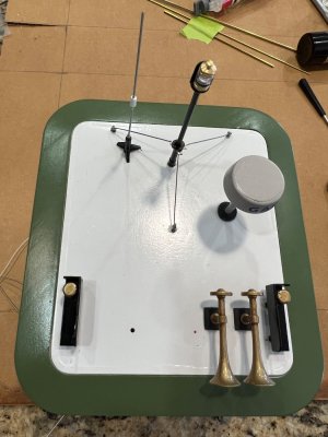
Primed and painted this is what it came out.
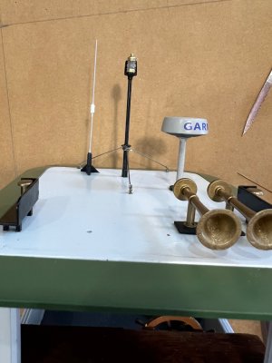
I think it looks neater and the makes the brass housing stand out.
Now, to finish all of the items in the roof, I just need to add the search light, but I have to wait for the LED to come from Amazone.
Previously I showed how I soldered this piece but I just couldn't accept it. Something about it that I didn't like, it looked too bulky so I made another one, but this time instead of brass wire I used stringing wire purchased from Hobby lobby.

I wanted to use a clear brass light housing that I had purchased from Harbour Models and for that, I had to recreate the entire light pole like this.


Primed and painted this is what it came out.

I think it looks neater and the makes the brass housing stand out.
Now, to finish all of the items in the roof, I just need to add the search light, but I have to wait for the LED to come from Amazone.

Another thing I didi today was to add the "Bottoms of the Pushing Heads".
These are a combination of four pieces of B22 on each side.

I made a huge mistake here. Something so simple it turned into a nightmare.
I ran a piece a tape from the upper pushing head edge to the bottom, but when it glued the pieces, I glued them in the wrong side of the tape, so I had to rip it off and filled the damage as you can see here.
This time I pencil mark them.
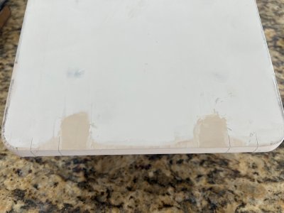
Since this bottom pieces are composed of 5 pcs, is just too difficult to cover the joints with paint, so I added two pieces of 1/32" ply.
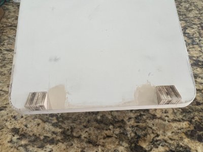
Like this.
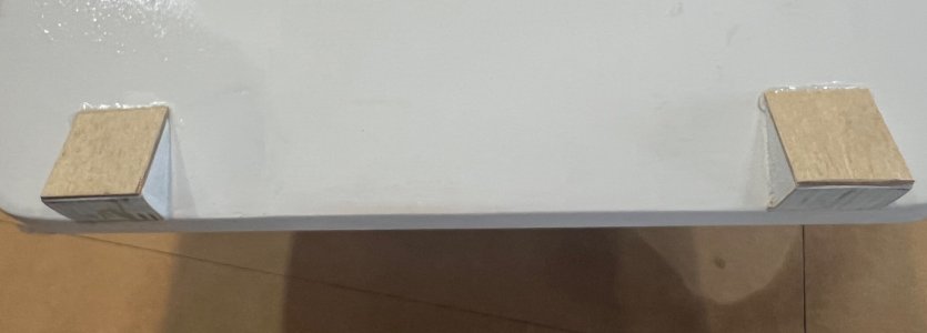
These are a combination of four pieces of B22 on each side.

I made a huge mistake here. Something so simple it turned into a nightmare.
I ran a piece a tape from the upper pushing head edge to the bottom, but when it glued the pieces, I glued them in the wrong side of the tape, so I had to rip it off and filled the damage as you can see here.
This time I pencil mark them.

Since this bottom pieces are composed of 5 pcs, is just too difficult to cover the joints with paint, so I added two pieces of 1/32" ply.

Like this.

I had to smile at your error because it is just what I have done several times over the years. I have duffasoidal tendencies while building things. If there is a way to flip it over or rotate it end for end I will do it. Build 2 lefts and no rights not a problem. Need a mirror image of a part, not an issue, the second time. If it is meant to be installed in a specific orientation you can bet I will clock it 180 degrees in the wrong direction. It’s a good thing boats have a sharp end because I know somehow I would be able to put the rudder in the bow.
Thanks for sharing your experience.
Thanks for sharing your experience.
This is another small detail that I came up with according to what I could define from pictures on the net.
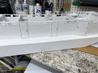
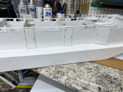
I added hinges, handles and jambs to all of the doors.
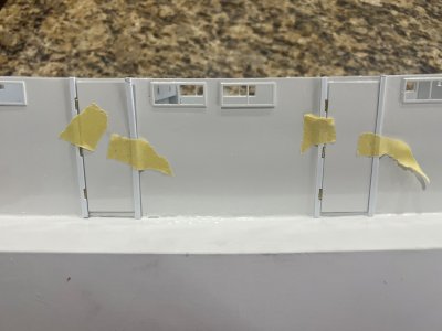
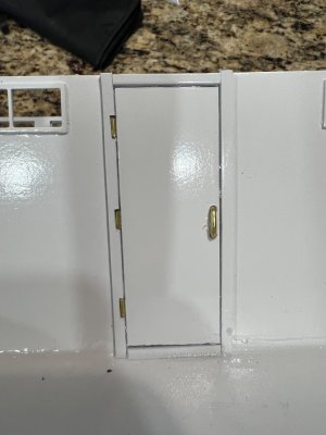
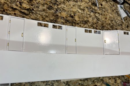
This is the super structure complete with white paint, hinges, handles and jambs.
Im still painting the sun deck but had to correct the painting because of some errors.
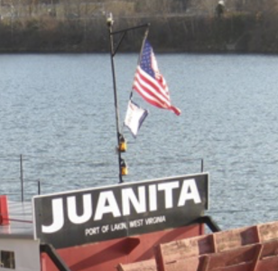
Today I'm designing and soldering together the stern lights and flag post.
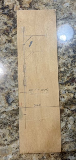
This is my little soldering jig.
More to come soon, like creating four gutters to drain water from the sundeck, tow on each side.
I still don't know how to create them, so Im open for suggestions.
Here is picture, of the actual gutters.
They look square and rounded at the bottom.
Any ideas?
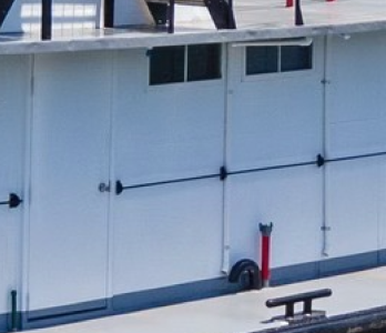
I added hinges, handles and jambs to all of the doors.


This is the super structure complete with white paint, hinges, handles and jambs.
Im still painting the sun deck but had to correct the painting because of some errors.

Today I'm designing and soldering together the stern lights and flag post.

This is my little soldering jig.

More to come soon, like creating four gutters to drain water from the sundeck, tow on each side.
I still don't know how to create them, so Im open for suggestions.
Here is picture, of the actual gutters.
They look square and rounded at the bottom.
Any ideas?

Last edited:
impecable trabajo, como siempre
Just checking.
Sorry guys that I haveS taken so long to post anything's else about this great model.
So, after so many try and error, Im ready to show what else I have accomplished.
First I have to star with the paint job,
This model require three main colors: white for the upper main structure, grey for the upper and lower decks, and black for the hull.
So, here is my taste of how the color should go.
This is the model with two coats of primer.
The first color I did was the main structure in white.
Here you can see that I added my own door jams, hinges and handle.


Now, I did something different with the pilothouse roof color. It supposed to be the same grey as the deck but for some very reason that attracts me, I Painted it white. It does balance the colors. You know how it is: " Beauty is in the eye of the beholder".
Here is more of the super structure in white.
Another thing I painted in white was the top of the stairs. According to many pictures I studied, is supposed to be white, but then again....To me , and to my yes, it looked better in white to balance the entire structure.
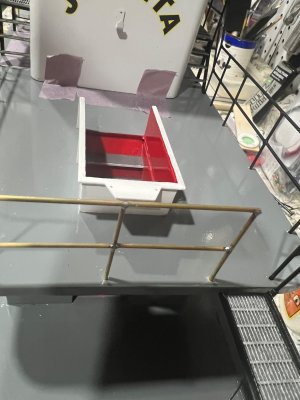
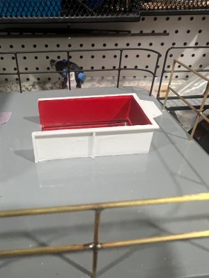
This is my second step painting the model. I painted the deck gray.
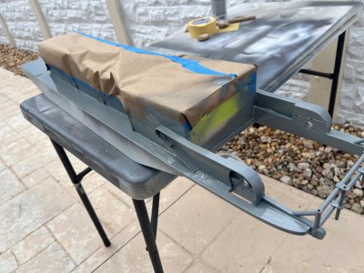

Another thing I didn't followed the rules was with the upper stairs housing. I like it in white better that in grey how is supposed to be.
After the white I did the deck in grey.


I had LOTS of problems when painting the sun deck with this color. I painted it three times and after drying it came back with wrinkling effects, maybe (some sort of contamination)/.
So it took me lots of days trying to strip it, patch it up and repainting it.
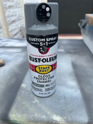
So, after so many try and error, Im ready to show what else I have accomplished.
First I have to star with the paint job,
This model require three main colors: white for the upper main structure, grey for the upper and lower decks, and black for the hull.
So, here is my taste of how the color should go.
This is the model with two coats of primer.

The first color I did was the main structure in white.
Here you can see that I added my own door jams, hinges and handle.


Now, I did something different with the pilothouse roof color. It supposed to be the same grey as the deck but for some very reason that attracts me, I Painted it white. It does balance the colors. You know how it is: " Beauty is in the eye of the beholder".

Here is more of the super structure in white.

Another thing I painted in white was the top of the stairs. According to many pictures I studied, is supposed to be white, but then again....To me , and to my yes, it looked better in white to balance the entire structure.


This is my second step painting the model. I painted the deck gray.


Another thing I didn't followed the rules was with the upper stairs housing. I like it in white better that in grey how is supposed to be.
After the white I did the deck in grey.


I had LOTS of problems when painting the sun deck with this color. I painted it three times and after drying it came back with wrinkling effects, maybe (some sort of contamination)/.
So it took me lots of days trying to strip it, patch it up and repainting it.

Last edited:
That was the finished stern section.
But I have to warn you that the back splash should be glue to the structure NOT TILL YOU HAVE PAINTED THE ENTIRE MODEL.
The back splash you have to paint it with three colors: black, red and white. After all of these paints had dried, then you have to add the decal and then seal the entire back splash with some kind of sealer. I used all through the model semi-gloss.
Here are all of the steps when adding the back splash.
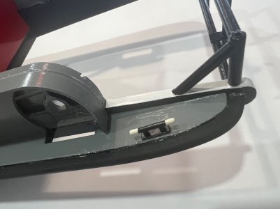
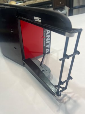
First you have to glue together the back splash brackets (comes with four pieces) and there is only one way of doing this, because these brackets has different sizes, one small and one larger.
Here is how the upper section of the bracket should look like. Do not glue them evenly on top, because only a thin part (The Outer) will go into the back splash slot.
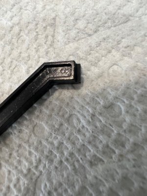
This is how is supposed to look in the bottom.
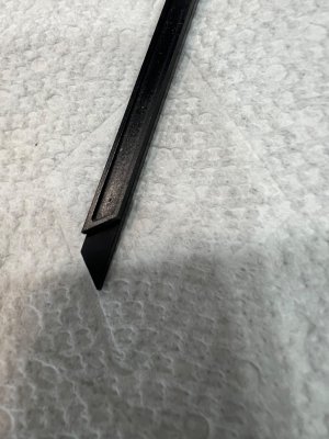
And this is the reason why it has to be this way.
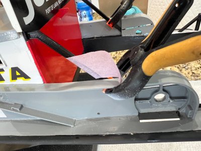
Because the monkey rudders mechanism cable tube runs through the bottom of the brackets.
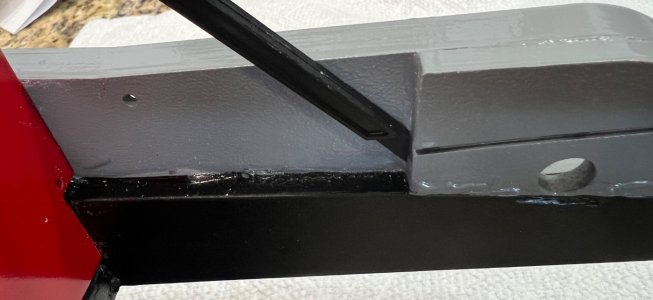
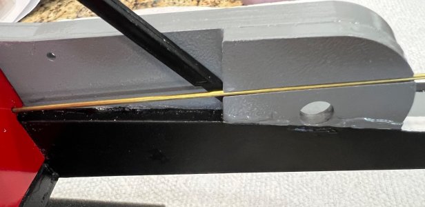
So, After I figured this out, (since is not in the instruction pictures) I glued the back splash to the structure.
You guys have no idea what I went through to just paint the back splash., The red color went wrinkling on me many times, so I had to strip and repaint the entire thing over and over till I got it correct,.
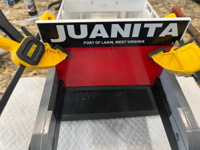
Gluing the brackets to the backsplash.
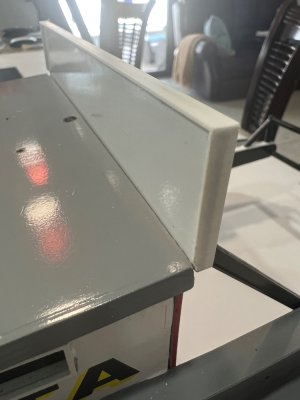
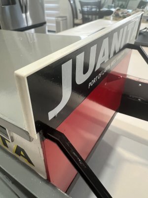
One more thing. The back splash has a styrene borer all around it that it has to be in the proper place. Here I used my own styrene, just a bit thicker.
 `
`
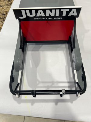
But I have to warn you that the back splash should be glue to the structure NOT TILL YOU HAVE PAINTED THE ENTIRE MODEL.
The back splash you have to paint it with three colors: black, red and white. After all of these paints had dried, then you have to add the decal and then seal the entire back splash with some kind of sealer. I used all through the model semi-gloss.
Here are all of the steps when adding the back splash.
First you have to glue together the back splash brackets (comes with four pieces) and there is only one way of doing this, because these brackets has different sizes, one small and one larger.
Here is how the upper section of the bracket should look like. Do not glue them evenly on top, because only a thin part (The Outer) will go into the back splash slot.

This is how is supposed to look in the bottom.

And this is the reason why it has to be this way.
Because the monkey rudders mechanism cable tube runs through the bottom of the brackets.


So, After I figured this out, (since is not in the instruction pictures) I glued the back splash to the structure.
You guys have no idea what I went through to just paint the back splash., The red color went wrinkling on me many times, so I had to strip and repaint the entire thing over and over till I got it correct,.

Gluing the brackets to the backsplash.

One more thing. The back splash has a styrene borer all around it that it has to be in the proper place. Here I used my own styrene, just a bit thicker.

 `
`
Last edited:


