• Ships of Scale has incorportated an extra level of security when you log In. Please follow on-screen prompts to acknowledge that you are not a robot via a "Check Box" or a "Pictorial Check Box Puzzle". This is needed due to higher level of AI Activity Security.
  • SUBSCRIBE TO SHIPS IN SCALE TODAY!

    The beloved Ships in Scale Magazine is back and charting a new course for 2026!
    Discover new skills, new techniques, and new inspirations in every issue.

    NOTE THAT OUR NEXT ISSUE WILL BE July/August 2026
  • Win a Free Custom Engraved Brass Coin!!!
    As a way to introduce our brass coins to the community, we will raffle off a free coin during the month of August. Follow link ABOVE for instructions for entering.

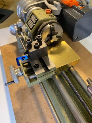
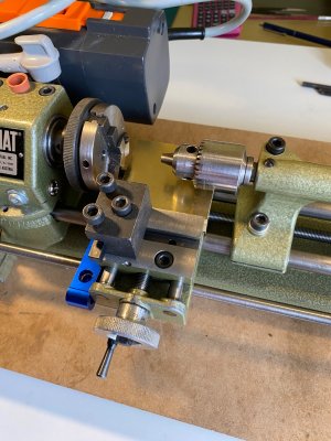
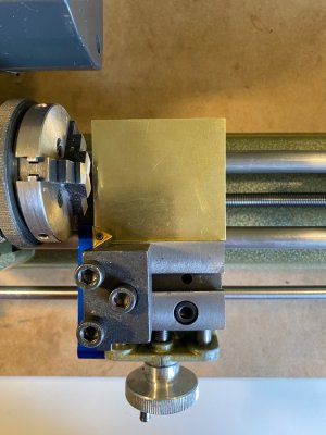
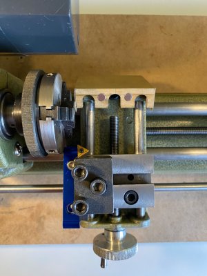
Unimat SL lathe. Carriage leading screw cover.

  • Thread starter Thread starter Y.T.
  • Start date Start date
  • Watchers Watchers 6
Joined
Sep 3, 2018
Messages
2,222
Points
538

Location
Toronto, Canada
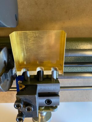
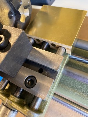
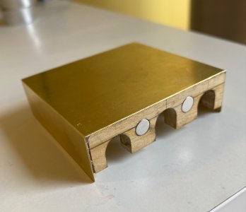
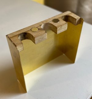
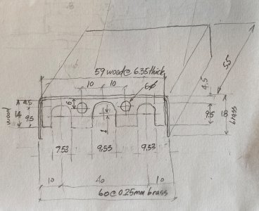
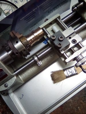
Unimat lathe has its leading screws exposed. This is an unfortunate feature that I wanted somehow to fix. Sometimes I don’t want to use Unimat lathe just because I have too much chips to clean. Attached pictures show what I had come up with to cover a short leading screw. If you have some ideas how to cover the long leading screw please post it here.

IMG_1635.jpeg

IMG_1636.jpeg

IMG_1637.jpeg

IMG_1638.jpeg

IMG_1639.jpeg

IMG_1640.jpeg

IMG_1642.jpeg

IMG_1643.jpeg

IMG_1641.jpeg
 
When I used my Unimat to bore holes ]down the center of cold rolled steel rod, I wanted to limit the mineral oil kerf lube and the curls - I used heavy oven grade Aluminum foil and molded it into the hollows and up just high enough to avoid moving parts. It worked about as well as anything could - but I still had to dissemble and clean - no fun atoll - time consuming - tedious.
 
thats a neat solution yt. i also like the tin foil cover too. easy peasey.

i used a soda straw to cover the screws... i cut the length to my chuck stop and my tool to center distance.

screw cover.jpg

i did see a screw cover that automatically retracts n expands as you move.... not for us but check out the idea of this?


Last edited:
Hallo zusammen,

Das sind alles sehr gute Ideen. Ich werde das für mich auch umsetzen, da ich die gleichen Probleme habe. Danke fürs Zeigen.
 
You know Roger, this may work out.

 
If each section of the tubing has a slightly different length - the largest being the shortest and the next a finger tip grip longer - getting them pulled back to max length will not drive you crazy with frustration.
 
telescoping brass tube may work but it wont retract n expand evenly because it hasnt got an inner lip to pull n push the next section to follow.

the lead screw is 1/4", if metric would be slightly over 1/4"

i think my grand daughter has some collapsible straws or some kind of toy that used them.

im sure one of us will find the solution... stay tuned?
 
Elegant solutions! I've long been a fan of tinfoil shielding for my lathes. I use it when turning wood and plastic on my metal turning lathes as well. Once the sawdust hits the lubed lead screws, there's hell to pay to clean it all up.
 
your guna like this... make gears on your lathe the easy way

you really dont need the fancy gizmo. you just need to hold the stock centered on the tool transport at the height of the tap. im sure we can figure out how to jig it up.

oh gears for a rope walk?
 
Last edited:
A couple of observations from a self-taught amateur hack machinist:

Hobbing the pulley is an interesting trick. The two concerns I'd have are: 1.) It sure looks like an easy way to snap a tap and 2.) I'm wondering what effect the hobbing will have on the wear rate of that plastic belting.

As for the gear making, that's really an amazing solution to an otherwise tedious exercise, but how does he get the spacing the gear teeth to come out even regardless of the circumference of the gear? It would seem that, short of some fancy math and some very exact measurement, you'd end up with a fraction of a gear tooth if the circumference of the gear wasn't exactly evenly divisible by the distance between the gear teeth. Can somebody explain that one to a beginner like me.
 
It may be so minor that it is of no consequence but all of the taps that I own have helical cutting teeth.
How does the cut gear have vertical internal faces and not sloped?
Good point! Add that to my questions. It almost seems like the tap is being used like a knurling wheel and not really "cutting" at all. Just "mashing." Note that he's working aluminum and brass, not iron or steel.
 
yes great questions. since finding the video ive been racking my brain with the same question... how can you accurately determine the circunference of a gear when hobbing, so it doesnt leave you with an odd tooth. it has to overlap evenly through out the circumference.

so i went digging to find answers. its mind boggeling complicated!... or at least i just cant find a simple answer as you'll see here...


https://www.nidec.com/en/machine-tool/knowledge/column/cutting-tool/cutting-tool-hob-02/

but but it looked so simple? for us laymen the best answers can be found by trial n error.... you just gotta do it to find out just how many teeth your hobb will cut per a set distance. then apply that to the circumference of the gear. maybe as simple as the tpi pitch of the hobb? sounds like a fun project to me.

im sure knurling works on a similar principle, except the hobb is actually cutting or shaving, rather than mashing. also it seems hobbs n taps are different although the video is using a tap.

if using small taps, you would have to be gentile on your feed rate and speeds. also working non ferrous material is much easier on the tap. after all, we arent cutting gears for a tractor's transmission.

the question of sloped teeth... in the video i did see the gear was turned over for a second cut. or perhaps a slight angle between the work and hobb can alleviate the slope? also thin gears wont have enough tooth thickness to matter.

once again, we have to put the rubber to the road instead of burning up whats left of our gray matter.

now improving traction on pullies... im sure the sacrifice is lower milage on the drive belts... thats the trade off. im not worried about the slippage, it's actually saved me in a jam a few times. I'd rather the motor keep spinning than tear up the belt.

ya gotta say, its a fun way to play with our lathes. besides, once we figure out how to make gears, there is no stopping us anymore from doing more complicated projects.

lets have some fun?

 
Last edited:
I thought about knurling with my Sherline lathe. Really easy, just squeeze a rotating metal bar between a pair of engraved rollers, right? Then I read detailed instructions for doing it. Much more complicated! A short lived idea.

Roger
 
Back
Top