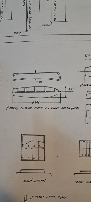
USRC Harriet Lane Model Shipways 1:96 scale circa 1863

Hi Chuck,
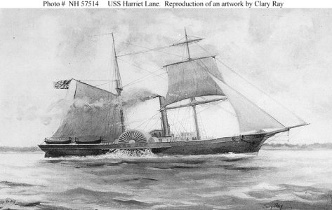
Just from a construction point of view, I don't think that there would be enough lateral support for the davit to be mounted on the bulwark. Mounting the davit to the deck would provide an area where the davit could be bolted through the deck and be supported by the bulwark to prevent lateral movement. Below is an interesting picture I found. It appears that, in the picture, the davits may be outside the bulwark. Maybe bolted to a rub rail. Hmmm.

Bill

USS_Harriet_Lane.jpg
 
Sorry, I've been going in circles with a new web-host and not paying attention...

The type of davit most common in photos of CW ships are "radial davits," like this kit. Some had a single or double block made into the top end, some, like shown, had an eye for a block to be attached. The typically sat in sockets on the channels, or the side of the hull, with a strap or a ring holding them part way up, all so they can pivot. It was less common to mount them on deck or through the cap-rail. Up through the war They normally held one boat per pair. The big ones holding two, even three boats, are post war training ship things - training ships do a lot of boat work.
View attachment 502290

Boats have been typically carried on the quarters, since quarter davits came into fashion in the 1790's. Most pictures I see of the Lane show her carrying four boats, 25ish foot cutters from the looks of them which is some 50+ feet of boat hanging in davits on either side. She may have had a gig or jolly-boat (16 footer maybe) hanging off the stern on up on the house. IMO, the davits should be mounted outboard the bulwark something like in the pic of the Housatonic. Note there's a lot of length against the hull because, and especially in your case, there' not a good way to run a support line from them and up the mast, they need to support themselves. You can't get that needed leverage mounting them inboard on the deck.

View attachment 502294
Jerry! No worries, my friend! I hope the new web host works out.

Thanks for the info! Spot on as usual! I'll see what I can come up with. Again, something to deal with at the start of the build rather than the end. The slope outboard so far aft is pretty steep. Fingers crossed :oops:

Blessings.
Chuck
 
Hi Chuck,
Just from a construction point of view, I don't think that there would be enough lateral support for the davit to be mounted on the bulwark. Mounting the davit to the deck would provide an area where the davit could be bolted through the deck and be supported by the bulwark to prevent lateral movement. Below is an interesting picture I found. It appears that, in the picture, the davits may be outside the bulwark. Maybe bolted to a rub rail. Hmmm.

Bill

View attachment 502295
On the Flying Cloud the davits are mounted outboard into sockets on the rather pronounced planksheer.


Bill! Pete! Good work shipmates! What you say jibes with Jerry's info. Many hands make light work. So glad I asked the question before I did the work this timeROTF

Love the picture, Bill! Well done! I think the davits are definitely outboard. Nice to see the conclusion confirmed!

Pete, you're describing my situation exactly. Any pictures? Please? :)

Blessings.
Chuck
 
Sorry Chuck I have no idea so I am of no help with regard to your Davit problem ;) . Cheers Grant
Grant! How can that be? ROTF Don't you worry my friend! I am considering which of my two Maris Stella galleys will be next in the building slip - I'll be looking real hard in your direction.:p

Thank you, Grant!

Blessings.
Chuck
 
Bill! Pete! Good work shipmates! What you say jibes with Jerry's info. Many hands make light work. So glad I asked the question before I did the work this timeROTF

Love the picture, Bill! Well done! I think the davits are definitely outboard. Nice to see the conclusion confirmed!

Pete, you're describing my situation exactly. Any pictures? Please? :)

Blessings.
Chuck
Here are pics from Flying Cloud and Flying Fish plans and the approximate location of the davits ("Davies") on the planksheer on my model. The planksheer, as you can see is very pronounced and robust.20250220_115148.jpg20250220_115256.jpg20250220_115940.jpg20250220_115426.jpg The second picture is from the interior looking out.
 
Pete! You've come through for me buddy! This is super helpful! What is happening with the davit rigging offscreen? See red arrow. And, please, send a picture :p

Davits.jpg

I've made a quick sketch of a view from aft below. The idea is a right angle as described by the yellow lines rather than the red line that follows the angle given by the curve of the ship. Right?

Davit drawing.jpg

Thank you again, Pete!!!

Blessings.
 
Pete! You've come through for me buddy! This is super helpful! What is happening with the davit rigging offscreen? See red arrow. And, please, send a picture :p

View attachment 502462

I've made a quick sketch of a view from aft below. The idea is a right angle as described by the yellow lines rather than the red line that follows the angle given by the curve of the ship. Right?

View attachment 502463

Thank you again, Pete!!!

Blessings.
Looks right I'll re-take that shot tomorrow to include the off-screen detail.
 
In the early 1850’s, American merchant vessels trading to China were harassed by pirates who would attack and then retreat into shallow water. The US Navy had no shallow draft vessels to deal with this threat. As a result, Congress authorized construction of a shallow draft steamship able to patrol shallow Chinese waters.

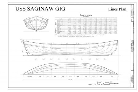
The result was USS Saginaw, a paddle wheel warship looking remarkably similar to Harriett Lane. Saginaw is famous for being wrecked on Ocean Island somewhat near Midway. Five crewmen using Saginaw’s Gig modified with decking sailed to Hawaii, and got help that rescued the crew marooned on the island.

I looked up Saginaw to see if I could find photos dealing with your boat stowage issue. I didn’t find any but I did find drawings of the gig. The gig survived and was returned to the Navy. After being shuttled around, it is somewhere in the Navy’s collection. Someone, recently took off the gig’s lines and other dimensions, and prepared a drawing. The gig is 25ft long with a beam of 8ft. Although no internal details, enough information exists to shape an accurate hull. This could be the double ended bOat on your aft davit.

Google Saginaw gig.

Roger
Good morning, Roger! Thank you! This is some nifty information! I think my second boat is about 28 scale feet long. I'll check out the Saginaw's gig. :)

Blessings.
Chuck
 
By the time that you finish this model you will know more about Harriett Lane than the guy who designed the kit. That’s a problem with kits. In this case the kit designer is a well known expert on the Eighteenth Century British Navy, not the mid Nineteenth Century America Navy/Revenue Service. I also doubt if he was paid to research Harriett’s design. He was probably told to re-engineer the 1:144 solid hull kit into the 1:96 scale POB one. At least your kit has “good bones” that allows you to build your handsome model.

An excellent resource for Mid Nineteenth Naval vessels outfit is William Brady’s The Kedge-Anchor (Dover Reprint). For Second Class Steamers five boats are listed; a 30 ft Launch, a 28.5ft Cutter, and three 26ft cutters.

Of course, you don’t have room for five boats and Harriett Lane was a Revenue Cutter not a naval vessel. So, the takeaway here is that the Navy did use 26ft cutters, and we know that a vessel of the same era was outfitted with a 25ft gig. Perhaps fitting these smaller boats between the paddle boxes and counter stern makes more sense.

Roger
 
There's also lines for various boats of this period in the appendix of History of the American Sailing Navy (Chapelle)
The issue with the davits is why the hung clinker built boats from them. A framed, carvel planked, boat would weight nearly double that of a clinker boat and be more prone to sag.
 
Last edited:
There's also lines for various boats of this period in the appendix of History of the American Sailing Navy (Chapelle)
The issue with the davits is why the hung clicker built boats from them. A framed, carvel planked, boat would weight nearly double that of a clinker boat and be more prone to sag.
Jerry! Thank you for adding your expertise!

Blessings.
Chuck
 
What ho, shipmates!

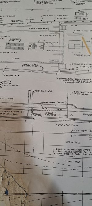
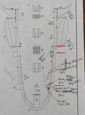
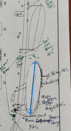
Before I get further into the boats and davits I want to go back to the conversation about deciding on attachment and belaying points for additional rigging for current or future builders. As we've noted, a fair piece of the problem I created would have been avoided with really thinking the problem through. For example, I should have known and planned for the 16 additional belaying points I needed for the running rigging on the fore yards. The problem would have been solved, as we've discussed, by adding cleats to the masts. Having pondered my blunder forward, I took out the plans and marked them for the belaying points forward (too late) and aft (just in time).

Pictures below show my ideas for belaying. I stopped to think about it because I was worried about the boat davit placement interfering with attachment and belying points I had already set up for the main gaff and boom - vangs and guys, and the belaying point for the fore yard braces. As you know this led to the wonderful discussion of davit construction, location, rigging, and boat sizes (really wonderful display of what membership in the forum adds! Thank you @JerryTodd @Roger Pellett @Peter Gutterman !!!) In the process, also, strangely enough, referring to the instructions, I was led to think about the need to belay the lines of the boat tackle.

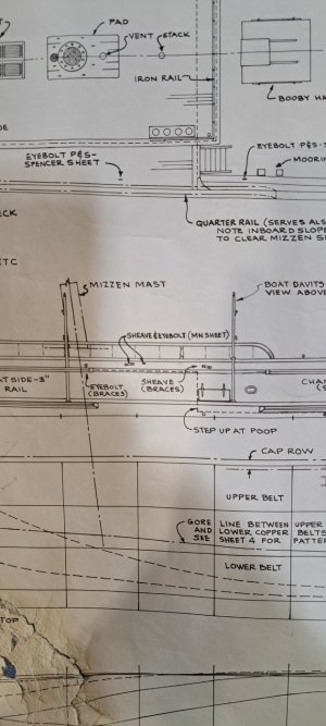
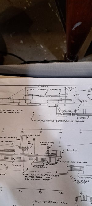
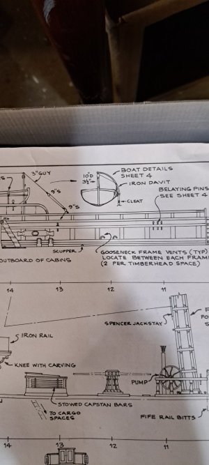
Here, a pic of the forward belaying points on the plan. I should have done this at the start of the build. If you are building or planning to build this ship, you should also add your pin rails on the bulwarks ;)

The blue arrows are for the eyebolts for the standing rigging, the stays that are inboard. Starting from the top - the foremast preventer stay, the foremast stay. The lowest blue arrow points to three dots where I set eyebolts for the lower ends of the main preventer stay and the main topmast stay. You can tell that this is a very narrow area to work in and I had a heck of a time getting the lower blocks hooked into these eyes. Note: at least for me, setting up the lower ends of these stays first worked the best - all of the running line was already rigged and I did not have to go through the nightmare of trying to add the running lines in that confined space.

The red line is the location of the pin rail. Everything else is labeled (or scribbled if you prefer) in notes in the right hand margin. All "k's" are cleats. The "K" is a larger cleat from the kit to handle the weight of the anchor belay. All "o's" are eye bolts.

Forward belaying map.jpg
 
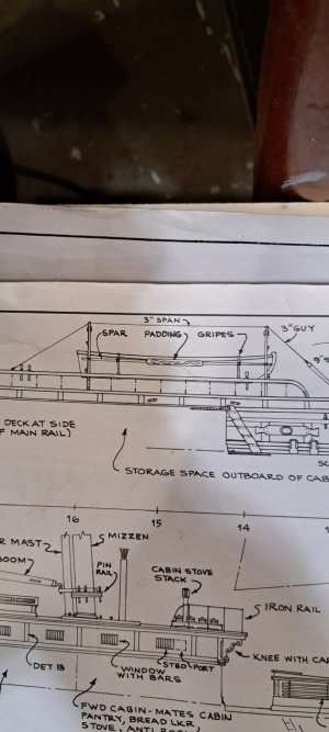
Here is the aft map. All notations in green are things that came to mind only after I started thinking about the boat locations. The red lines represent the presence of the davits. Based on the input about where the davits are properly shipped, the aft davit of the first boat is show outboard rather than inboard as shown in the plans. All k's and o's remain cleats (small) and eyebolts.

Aft belay map.jpg
 
Now, back to the boats. Note: I don't know if I said this already, but after finishing up with the foremast rigging (except the braces) I purposefully paused to think out the next sequences. I knew that if I rigged the topsail and t'gallant sail yard braces, they would be in the way of working on the mainmast rigging. During the pause it occurred to me that the next thing I needed to do was the boats, particularly the second boat, so that I wasn't trying to drill holes in the deck for the davits after all of the remaining mainmast rigging was in place:eek:. Been there, done that, have the tee-shirt and the hat.ROTF One of the first times I've been consciously patient and glad about it as we know from the posts about boats and davits.

I started on the second boats knowing that they would be double ended only because that was what Webb represented in his original plans. See blue arrows.
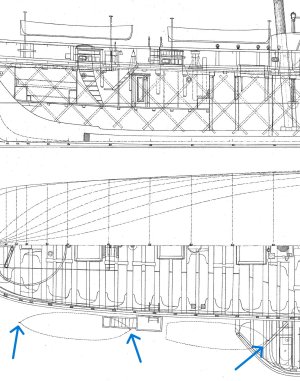
Double ended second boats.jpeg

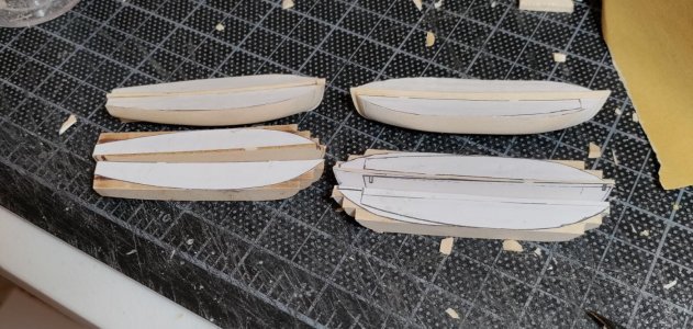
I wasn't thinking in any detail about the exact length and width. I was merely thinking about making the second boats visually different than the first boats. I was also thinking about how to make the second boats. Here's how: In my stone-age tool chest is a printer (paper only - don't get excited about that 3D business). The printer can also make copies! The kit comes with profile templates for the top and stern of the first boats. This template is pretty thick - almost card stock. I used it only to make several copies.

The kit also includes the laser cut parts for the first boat. The first boat has three main components - port half, starboard half and a center keel. I also made photocopies of these. The halves are composed of three pieces in diminishing sizes that are laminated to each other. It is very clear how to do this. Not so clear is the instruction to "apply" the profile templates to the half. I decided that this meant glue the template to the top and rear of the half so that you know the shapes you're trying to carve to. The instructions, however, tell you not to bother removing the laser char. This seemed wrong for the top and stern. Unless the laminating process left you with a perfect surface on top and aft, how was the profile template supposed to lie flat. Since nothing I ever do is perfect, I sanded the top and the stern smooth and used Elmer's (water based white glue) to "apply" the profile templates cut from the copy paper.

With the second boats, I took the top profile and center keel photocopies and overlapped them until my eye told me that the second boat was long enough. I then took the photocopies of the three components of the boat halves and glued these to scrap wood from the kit of the same thickness of the components of the first boat. The thickness of the copy paper added an extra 6 scale inches to the width of the second boats.

I didn't do a great job photo-documenting my process, but I hope you get the idea from my description and the pics I took.

This is a pic of the laser cut parts for the first boats. The blue arrows show how much should be left showing of the next lowest piece.
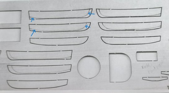
Boats 1.jpg
Below you can see that I taped two halves of the top profile of the second boat together to get an idea of how it would look against the plans.
Boats 2.jpg

Here are the center keel pieces for the second boats. I took the photo copy of the actual part from the first boat. I glued these to scrap from the kit of the same thickness as the center keel for the first boats.Boats 3.jpg

This shows a half of the first boat before assembly and the profiles of the 2nd boat before applying them to the scrap wood.

Boats 4.jpg

The rest of the pics speak for themselves.

Boats 5.jpgBoats 6.jpgBoats 7.jpg

Final note - Scaled out, the first boat is 22 feet by 6 feet. The second boat is 25 feet by 6.5 feet. Based on the Saginaw gig, the length is about right, but the second boat is a bit skinny by 1.5 feet or 3/16". Visually, however, the second boat looks longer and fatter than the first boat. VICTORY!

Now on to painting and covering the boats and davit fabrication.

Blessings. Peace. Gratitude.
Chuck
 
Back
Top