USS BONHOMME RICHARD - POF - Cross Section in Cherry - 1:48 - by neptune,

Joined
May 25, 2017
Messages
3,377
Points
688

Location
Australia.
I have had these kits for approx two years now and I have been holding off starting them, once Uwe started his build log it got my juices flowing so here goes, and by the way I will be building two of them at the same time, I will post some pics of the kit contents in awhile, but for now,

1.jpg
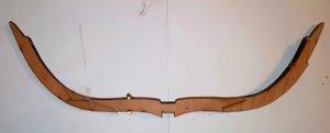
This is the parts that make up into the building cradle ( jig ), all the parts were clean cut and are well marked for there
positions,

2.jpg
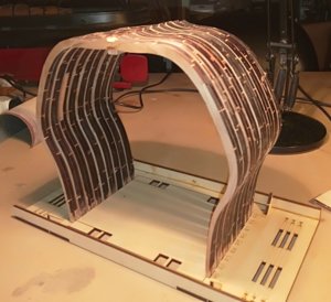
The cradle after assembly, thye frames will be built up and then placed in the cradle upside down,
3.jpg
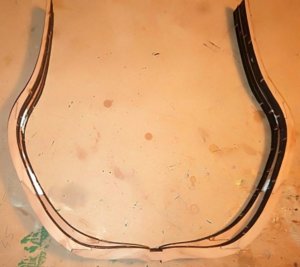
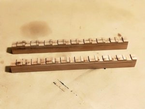
This is the two keels glued up, I will run them through the milling machine to cut the rabbet,

.
 
Hello again Jim, I meant to say that I have been thinking of a way to sand all the char from the frames in one go, you got me thinking about it with your comment in Uwe's log, I have been thinking of using chocks to join the frames together, or some sort of a railing that can be bolted to the frames to hold them secure, anyway it's bed time now so goodnight,
 
Hello again Jim, I meant to say that I have been thinking of a way to sand all the char from the frames in one go, you got me thinking about it with your comment in Uwe's log, I have been thinking of using chocks to join the frames together, or some sort of a railing that can be bolted to the frames to hold them secure, anyway it's bed time now so goodnight,
IMHO, John, sanding (removing char) on all frames when they on the jig would be a better idea. You can control both the entire body and the thicknesses of the frames at the same time.
 
Well this is the start of building the frames,


4.jpg
There are plenty of pics but no English instructions, so I just followed the pics, on the first page it shows
Rib one laid out and the sequence it is built

5.jpg
So I glued the two floors together and just put a spot of glue on the back to hold them to the white cardboard,
so they wouldn't move around


6.jpg
and then continued attaching the next parts, once I had the top parts of the frame in place I clamped them, see
pic two pics down,

7.jpg
The fit of the joints were very precise, even after having the char
removed with small files,

9.jpg
This is how I clamped the joints as i went,


10.jpg
You can see how nice a fit they are in this pic,

19.jpg
Having said that the joints are a nice fit, you still have to be careful because there is a correct way of assembling
them, in the pic above you can see the gap on the lower joint, the top of the joint is apart but the bottom is tight
so it looks like the V next to it, hope I am describing this properly, so although both port and starboard pieces are
laser cut you have to make sure the right one is used,


20.jpg
and this is with the right part,


21.jpg
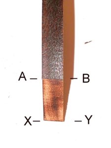
and apparently this is the reason why, you can see the parts have been laser cut with
an angle, the technical minded might know the reason for this, I'm just emphasizing
it so you will be aware,

If this is not clear and you need any more info just ask,

thanks for looking,

,
 
11.jpg
This by the way is a continuation of the previous post, and it is frame 9, I just wanted to see how different a shape
it was from frame 1, the next frame I made was frame 1 and I compare the two in another pic,

12.jpg
Frame 9 finished,

13.jpg
and in the jig, no force needed it just went straight in, makes you confident in there cutting process,
 
15.jpg
This is frame 1 just sitting over the drawing with the clamps holding it while it drys,

16.jpg
and without the clamps,

17.jpg
Frame 1 in the jig,


18.jpg
and this is the last of the frames for the first cross section, got to do them all again for the second one, :(:):(,


14.jpg
and this is Frame 1 sitting over frame 5, not a lot of difference topsides but a lot down below, still got to clean
them up yet,

.
 
18.jpg
I must say that although all the parts go together OK, getting them out of the sheets
was a bit of a hassle, some came out OK but others I had to use my scroll saw to
release them, but all was well in the end,


22.jpg
these are some of the frames for the second cross section,

23.jpg


24.jpg
so all i have to do now is attach the top timbers to the last two frames and then that is all the
frames for both cross sections assembled,


.
 
Last edited:
I assume you are lightly sanding the char from joint surfaces prior to assembly as gluing char to char would likely not allow even the best wood glue to make a good permanent bond.
 
Hallo John,
I am happy to see, that you also started the cross section - so we can both compare and see a little bit how the other one is working.
So from now one, we are in the same "business" - wish you luck and success - and most important a lot of fun
 
Hallo John,
I am happy to see, that you also started the cross section - so we can both compare and see a little bit how the other one is working.
So from now one, we are in the same "business" - wish you luck and success - and most important a lot of fun


Thank you Uwe for your kind words, I wish you the same, but i think yours will be a little bit better than mine, I think you are a bit more precise than me and study things more, where as I am like a bull at a gate, anyway as you say it is all a matter of enjoyment,

best regards John,
 
25.jpg
I was not too happy with the keel made up from all the pieces, so i had a nice piece of Pear and I cut new
keels out of that and to save a little bit of messing around I am just going to leave it flat on the top,

26.jpg
Because I was leaving the keel flat on the top I had to file away the step inside the frame so it would
sit nicely on the keel,

27.jpg
the frame just sitting on the keel,

28.jpg
I then filed off the char where the keelson sits,


29.jpg
The first frame and the last frame are glued to the keelson, but all the others are just sitting there, they still
need a little bit of tuning,


30.jpg
another view,
.
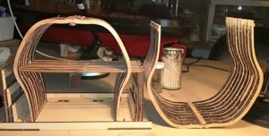
 
Seeing as I am going to remove the char from all the frames at the same time I needed to make sure the frame
work was stable and wouldn't move when I was sanding it, so I decided to install some chocks ( support pieces )
I was lucky that on each side of the sheets of Cherry that the frames came out of there was enough wood left to
cut some strips of the right width and thickness to make these chocks,

31.jpg
The sheet that the frames came out of, and above some of the strips I cut off the edges,

32.jpg
Now this is where the Chopper comes in handy, i just set the size and away I went,

33.jpg
one of the pieces ,

34.jpg
I glued these across between the frames sitting on the underneath of the keelson and
I made sure that the keel would still fit on OK, these really strengthened the framework,


35.jpg
I also added some halfway down the frames and also along the top of the frames and just to make sure I
added a sacrificial strip of wood along the outside of the framework, best be safe than sorry, it means that
I will have to modify the jig to get to get the frames back in, i will show that later on,

36.jpg
So after a busy day, the section on the right is ready for sanding and the second section on the left is in the
process of having its chocks attached, I will wait till the second section is all chocked and sand both at the
same time,

Thank you for looking and all the comments and the likes,

best regards john,

.
 
Last edited:
Back
Top