• SUBSCRIBE TO SHIPS IN SCALE TODAY!

    The beloved Ships in Scale Magazine is back and charting a new course for 2026!
    Discover new skills, new techniques, and new inspirations in every issue.

    NOTE THAT OUR NEXT ISSUE WILL BE MARCH/APRIL 2026
  • Win a Free Custom Engraved Brass Coin!!!
    As a way to introduce our brass coins to the community, we will raffle off a free coin during the month of August. Follow link ABOVE for instructions for entering.

USS Constitution by BlueJacket 1:96

Hi Peter
Thanks for the compliment. You are quite correct, once the spar deck goes on, much of it will be covered, but with the sections I'm leaving out, I hope enough of it will be visible that observers will at least have a sense of the detail in there. Not sure how much of my build log you saw on MSW before the crash, but I did install some lights on the gun deck to help make things more visible. Regardless of how much ends up really being able to be seen, I did it for the enjoyment and challenge, and believe me, at 1/96 scale it is a challenge :)
 
Before you close up the gun deck, I suggest getting some up close photography done so that you can post 8x10 glossies around your completed build to show off what most people won't be able to see.

And thinking of your kindred spirit, have you asked if he has a copy of your build saved? If so, maybe you could use that to piece together your own document replete with excellent photographs as coffee table supplements to your Constitution upon completion.
 
Actually Peter, he reached out to me. You can imagine how thrilled I was to hear he had my entire build log copied. Jon is amazing. I hope one day to actually go see him, as he only lives about 5 hours away.
As for putting together a nice photo montage, that's a great idea. Would make an excellent coffee table book
 
So, as I predicted, it took six wheels to get two that I could live with. I thought I would post a few pics of the gig I made to help with drilling the holes.
20260510_163407.jpg

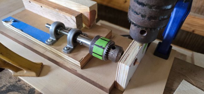
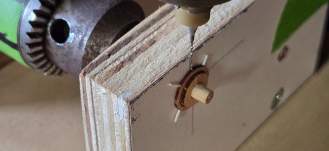
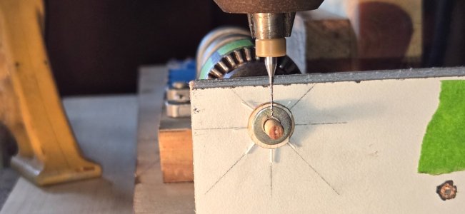
Nothing fancy. I first attached a piece of laminated plywood to the end of another board making sure the two were perfectly square. I used the laminate because it has a nice smooth surface for the wheel to rest against. I then mounted a drill chuck with a couple bearings. This allowed me to secure the dowel that the wheel was pressed onto and enable me to rotate the wheel without it changing orientation to the drill in any way. A hole was drilled in the laminate to allow the dowel to pass through. After pressing the wheel onto the dowel, it was pushed in flush against the laminate and the chuck tightened. Finally, a couple boards were clamped to the drill press table to position the wheel directly under the bit and allow me to keep it firmly in place. I'm sure this would be much simpler if I had an X-Y table.
Once the wheel was in place, I pressed another onto the dowel to keep the one being drilled firmly in place. The position of the first hole didn't really matter, but everything after that had to be relative to the first. To keep track and to make sure everything was orientated correctly, I put .020" plastic rod into the hole for reference. Then, I could rotate the wheel and make sure the plastic rod was perfectly opposite the next hole to be drilled and plumb with the drill bit

20260510_163911.jpg 20260512_160757.jpg

As mentioned before, the wheels are only .040" thick and the hole is .023", so not much forgiveness. Biggest challenge was being perfectly centered and making sure the wheel did push away from the laminate as the drill bit came down.
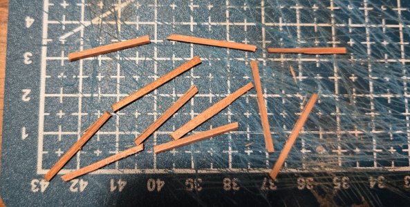
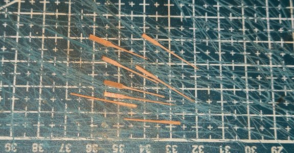
With two acceptable wheels in hand, I set about making the spokes. As I did with the pine, I cut some very thin strips and chucked these in my dremel the used sand paper between my fingers to whittle them down to tiny dowels approx .020" diamter

20260510_152746.jpg 20260512_233152.jpg

Next up is to make the drum and drill holes to accept the spokes
 
Dear Frank! You're doing well. But both in the 18th century and today, the steering wheel on the Constitution had ten spokes.
 
Kudos to your McGiver(ing?) skills. I would have long since been online ordering a milling machine with dividing attachment. But different strokes for different folks. All the more Impressive.

When I come to visit to see your build, I promise I won't count the spokes. I hate to see you spend another 6 weeks.
 
Well, to quote Adam Sandler (50 First dates) "That sucks!"
I first couldn't believe I would miss a detail like this but then realized why. When I first started working on the wheel using pine, I used the Revell ships wheel as a guide. It has 8 spokes. The Brittania metal wheels supplied in the BJ kit also have 8 spokes. Both of these kits claim to be accurate representations of her 1812 appearance and based on a lot of research.
So, what are my options:
1. Drill additional holes in the wheels I have. Considering only two of the existing holes are positioned properly, that would mean 8 more holes in a piece of wood that is already so fragile it will break if you look at wrong...not an option.
2. Make new wheels. Although I have gotten better, it likely would still take a few attempts to get good results and use up a lot of very limited wood. Not a great option
3. Keep what I have. Considering that if I were using the kit supplied wheels there would be 8 spokes, and like Peter, I doubt seriously anyone will ever know the difference or bother counting, this seems to me to be the logical answer. Moving on.
Igor, thanks for looking in on my build and for pointing out the discrepancy. It will just have to be our secret :)
 
"That sucks!"
"Your eloquent words perfectly capture the tragedy of the situation". (Craig Alanson)
Been there, done that, brought home the t-shirt. (Der Alte Rentner)

Happy to visit you on FL as long as you're withing a few hours drive from Sarasota (Lido Key to be specific) when I visit family there in February. :cool:Thumbsup
 
I know Lido very well. Beautiful beach there. It is "a few" hours from here, 3 to be exact. Not exactly close, but not terribly far.
 
So, thought I would post a little update. First off, I tried to make a small dowel from the wood that I have. Unfortunately, I only have a cheap little Chinese lathe. I tried actually turning the wood using a cutting tool, but between the tool and my extreme inexperience, it didn't work out too well. I switched over to using sandpaper, much like I did to make the spokes, however, this creates it's own set of problems. Since the heartwood is harder, it doesn't sand as easily and so what ends up happening is that you end up with more of an oval shaped piece than being perfectly round. So, after wasting a lot wood, and considering the drum is basically going to be obscured by the rope, I decided to just use a standard dowel for the drum. I can still say the ship's wheel is made of real "Connie" wood, just not the entire thing.
After drilling some holes in a regular dowel, I set about making up the wheel, which ended in disaster. I first need to remove the center piece
20260510_104433.2.jpg
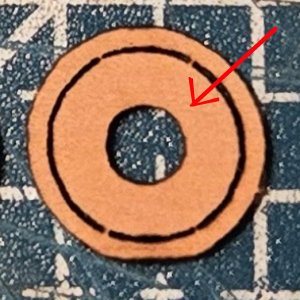
If you look closely, there are four small tabs that hold the inside piece to the outside ring. It should have been easy enough to cut these and let the piece fall out. However..... this wood seems to be a bit softer than the pine I had worked with earlier and getting a blade into this tiny little cut, combined with the holes weakening the outside ring, it broke in the process. I thought I could manage to glue everything back together, but let's just say that didn't work out. Moved on to wheel #2 and ran into similar problems despite my extreme caution.
So, back to square one. This time, I plan to make the pieces just a little thicker, maybe .045 or .050". This will make them easier to work with and I don't think at this scale it will really be noticeable
 
Try as I may, I cannot see these tabs that are talking about.

It's probably more trouble than it's worth, but circling back to your hub, if you send me a small amount of the material you're dealing with, I could turn you the hub, if you provide the dimensions.
 
Thanks so much Peter, that is a very generous offer. Send me a PM with your address.

As for the tabs, they are pretty small. Looking at a clock, they would be at 11, 1, 5 and 7
 
With Peter's very generous offer, I am going to set the ship's wheel aside for now while I wait for this small dowel to make the drum. Meanwhile, I thought I would get started working on the pin rails and fife rails. Most of this looks very straightforward, and I can use the Navy plan 27076 for most of the dimensions. However, this plan is from the 1973 restoration and shows all the fife rails as being straight. The kit comes with a curved mainmast fife rail, and I believe this is how it was in 1812. Jon, I'm wondering if you happen to have plans showing the dimensions of this curved rail? If not, I suppose I could take measurements from the metal one supplied in the kit.
 
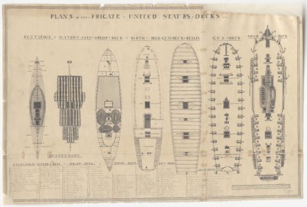
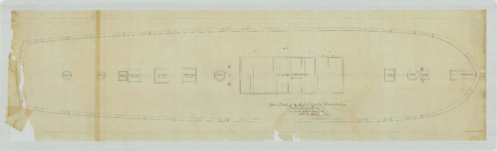
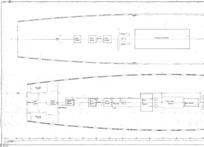
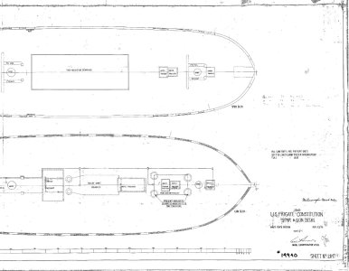
Attached are the plans that I have prior to 1927 of the spar deck arrangement plans. None show all (if any) pin rails let alone if they are curved or not. So I don't think they answer the questions you have. Sorry

Jon

45-Ware-15-DeckPlans.jpg

Spar Deck - RG19_ALPHA_Constitution_1797_08.jpg

14940001_1.jpg

14940001_2 - Spar & Gun Decks.jpg
 
Thanks Jon,
I'll just use the kit rail and the one from the Revell model to get some dimensions and go from there
 
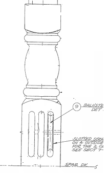
So after a long break, I finally have something new to post. I got to work on the fife rails and plan to also make these using the original piece of Constitution wood I have. I started with the foremast rails. Using the Navy plans from the museum website, I made a template for the rails and cut these from a piece that I had thinned down to .050". The template had only small dots for the belaying pin hoes that I used as a guide to actually drill the holes. Then came the sheave posts. According to the plans, these are 9.5" square which equals 0.1" at scale. Here is a cleaned copy of the posts from the navy plans
1779977442226.png
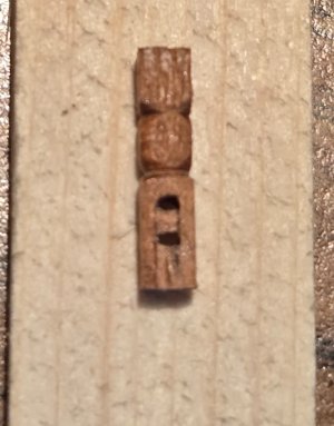
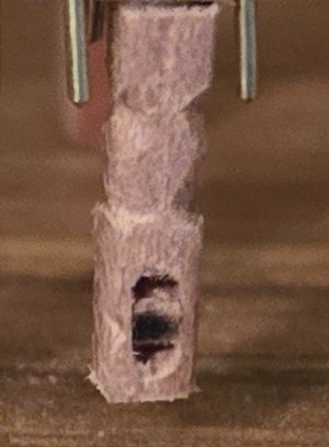
Although totally unsuccessful at making a nice round dowel for the ship's wheel drum, I could manage to use my cheap-O lathe to turn some semblance of the rounded portion of the post. As for the sheaves, I would love to have been able to make something as clean and beautiful as Mustafa's, but at this scale, I found that impossible, at least for me. I tried first just to drill two holes and hollow out the space in between. Once hollowed out, I then inserted a small piece to simulate the sheaves. This more or less worked, but the holes were not perfectly lined up, and the overall look was quite crude, albeit functional
20260528_102044.jpg
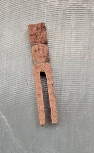
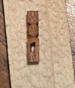
After doing four of these, I decided to try something different. Instead of drilling holes, I used the Byrnes saw to cut a slice out of the middle of the post, then I could insert a small piece of wood from the bottom to fill in the open space. This gave a much cleaner hole with nice straight sides. Once the hole was cclosed up, I again could insert a piece to simulate the sheaves
20260526_105908.jpg 20260526_134532.jpg 20260526_135847.jpg

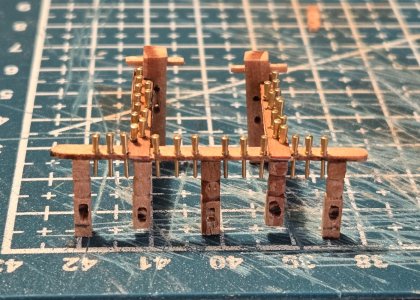
I felt this gave a much cleaner look. Next up were the Bitts. The Foremast bitts are slightly larger than the other fife rails, with dimensions of 13.5" square (.140" scale). After cutting a piece of square stock, I first cut a groove near the top to act as a mortise for the rail. The cross pin at the top is actually supposed to be rectangular in shape, but cutting a very tiny rectangular hole was going to be impossible, so I just stuck with a square piece with the largest dimension of 4.5" (.046"). I drilled a slightly smaller hole and then squared it up a bit using a square rat tail file and then just forced the pin into the hole. For the center sheave, I went back to just drilling two holes, but instead of completely hollowing out the space in between, I just made a groove, leaving the wood in the middle to simulate the sheave. Finally, there was the side sheave. This was made from a strip of wood that was .040" thick. Aportion as sanded down to .020" thick and then the piece was cut to length and shaped before attaching to the side of the bitt. There should actually be a sheave in the space, but I am just going to leave it as the space will suffice.
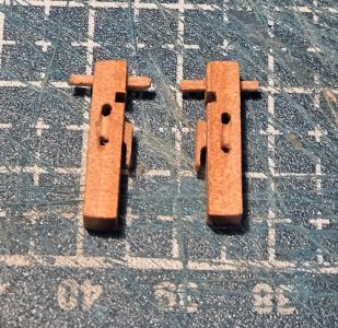
20260527_161446.jpg
I was pretty pleased with how they turned out. Finally, everything was glued together
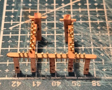
20260527_172624.jpg 20260527_172635.jpg

The pins aren't glued in yet, just there for the photo. They came with the kit and are very nice turned brass. I quite like the look of the brass and may keep it instead of painting them black as they should be. In the last photo you can see that the outside posts and the middle post are slightly longer. These posts are so thin that I don't think I could actually get a pin in them to secure them to the deck. Instead, I plan to actually mortise these and the bitts into the deck to provide additional glueing and hopefully keep them in place. The whole assembly is quite fragile, and I do have concerns when I actually start tying lines off to it later.

Next up is the Mizzen rail. I'm saving the main rail for last, as I plan to make the curved rail and it is considerably more complicated.
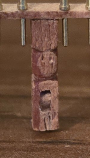

20260528_102054.jpg
 
Back
Top