


Thanks Jon. That does seem to be the problem. Gregg supplied me with a pic of Olaf Eriksen's plan from 1815. It is quite detailed and seems to be the best thing I'm going to have to go on, although even it has some discrepancies from what is known of the 1812 configuration. In any event, your above comment is probably the best advice and you are correct, most likely what they did on the actual ship."drillem" where you "needem" as most likely what they did on the actual ship.

-

SUBSCRIBE TO SHIPS IN SCALE TODAY!
The beloved Ships in Scale Magazine is back and charting a new course for 2026!
Discover new skills, new techniques, and new inspirations in every issue.
NOTE THAT OUR NEXT ISSUE WILL BE July/August 2026 -

Win a Free Custom Engraved Brass Coin!!!
As a way to introduce our brass coins to the community, we will raffle off a free coin during the month of August. Follow link ABOVE for instructions for entering.
You are using an out of date browser. It may not display this or other websites correctly.
You should upgrade or use an alternative browser.
You should upgrade or use an alternative browser.
USS Constitution - Model Shipway’s 5/32” = 1 ft. (1:76.8) Kit No.: MS2040


The Olaf Eriksen plan is really the belay pin plan that also shows the gun tackle eye bolts I mentioned earlier. Maybe that's all the eyebolts there were at that time. I don't know. Good luck, I look forward to your future posts.
Jon
Jon
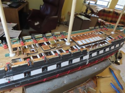
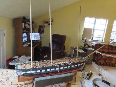
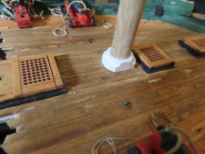
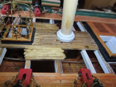
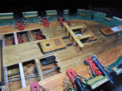
The fife rails have been assembled and glued, so I placed them on the deck just for a “look and see,” and noticed that I did not take the beam width of the fife rails into account when planking the reveal openings in the spar deck. The outermost main mast fife rail stanchions had no deck support.
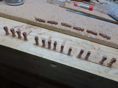
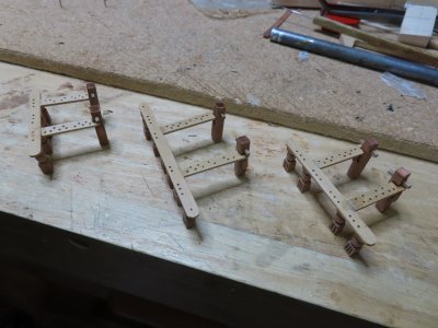
To resolve that problem, I added local planking for their support and dry fitted again.
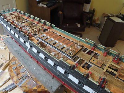
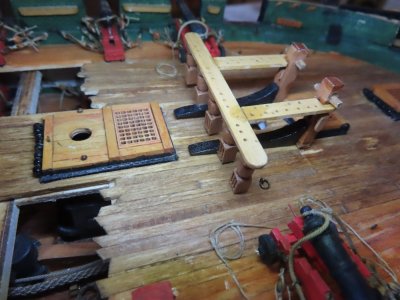
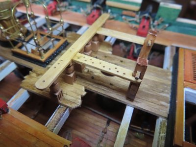
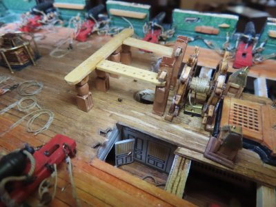
To resolve that problem, I added local planking for their support and dry fitted again.
Wedge Boot Mast Rings
Based on the successful dry fit, I assembled the kit supplied laser cut wedge boot mast rings. I wanted to make sure these components fitted together properly and on the spar deck. Each boot consisted of two rings stacked upon each other.
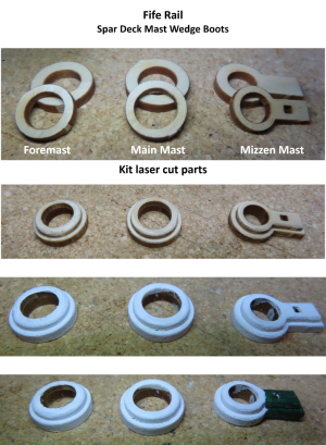
Based on the successful dry fit, I assembled the kit supplied laser cut wedge boot mast rings. I wanted to make sure these components fitted together properly and on the spar deck. Each boot consisted of two rings stacked upon each other.
The Foremast Riding Bitt Post Knees
The foremast fife rails have kit supplied laser cut riding bitt post knees. These were sanded, painted black, and fitted to the foremast fife rail assembly.
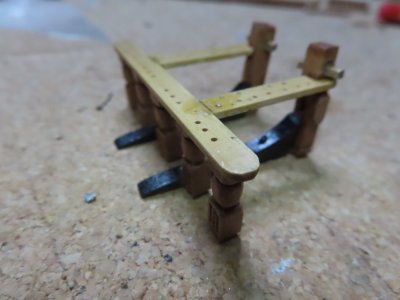
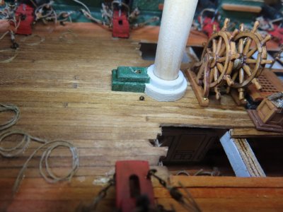
Unfortunately, the foremast wedge boot rings have a size discrepancy in the MS plans. Per the plan view of the spar deck on sheet 4, the foremast ring diameter measures 19/32” while on sheet 6 where the mast rings are described, the foremast ring measures 22/32”. The laser cut ring matches the larger size on sheet 6, doesn’t fit between the riding bit knees on the model. Due to the congestion of all the components in this area, I decided to take the easy way out, and trimmed the ring on two parallel sides so that it fits between the knees. Per another dry fit, it will not be easy to discern or recognize the compromise was made by the average viewer. There were no problems with main and mizzen masts.
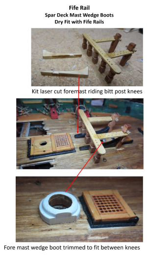
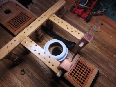
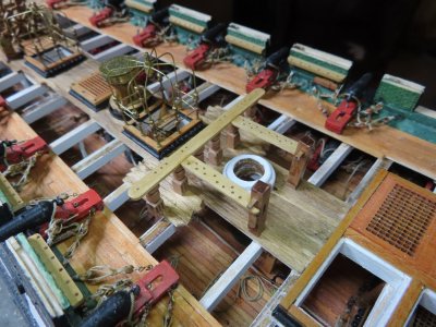
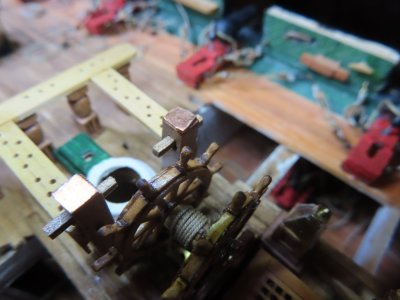
The foremast fife rails have kit supplied laser cut riding bitt post knees. These were sanded, painted black, and fitted to the foremast fife rail assembly.
Unfortunately, the foremast wedge boot rings have a size discrepancy in the MS plans. Per the plan view of the spar deck on sheet 4, the foremast ring diameter measures 19/32” while on sheet 6 where the mast rings are described, the foremast ring measures 22/32”. The laser cut ring matches the larger size on sheet 6, doesn’t fit between the riding bit knees on the model. Due to the congestion of all the components in this area, I decided to take the easy way out, and trimmed the ring on two parallel sides so that it fits between the knees. Per another dry fit, it will not be easy to discern or recognize the compromise was made by the average viewer. There were no problems with main and mizzen masts.

The fife rails have been assembled and glued, so I placed them on the deck just for a “look and see,” and noticed that I did not take the beam width of the fife rails into account when planking the reveal openings in the spar deck. The outermost main mast fife rail stanchions had no deck support.
View attachment 626985
View attachment 626986
To resolve that problem, I added local planking for their support and dry fitted again.
View attachment 626987
View attachment 626988
View attachment 626989
View attachment 626990
whew! Disaster averted. That darned law of unintended consequences can be a royal PITA!
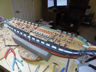
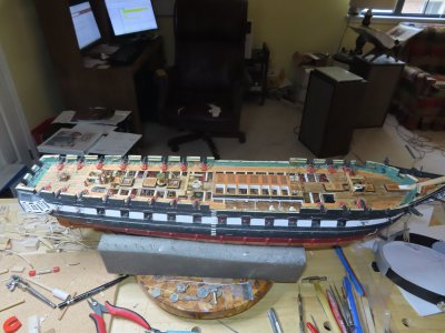
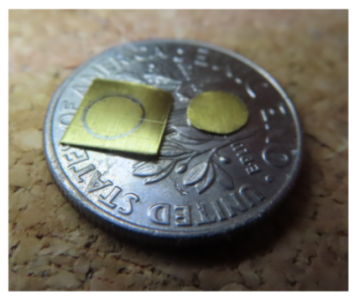
Before I could glue down the fife rails, I had to install the wedge boot rings. Since I had already configured mast dowels to their proper rakes of 3° foremast, 3.5° main, and 5° mizzen when I planked the spar deck, I used them as a jig to position the wedge rings and made sure the rakes were still correct. This is a classic case of one of Murphy’s Laws which states “that no matter what you must do, you must do something else first.” I also cut out of 0.005” brass sheet and installed the pairs of brass ammo scuttles by the mizzen mast and another by the main mast.
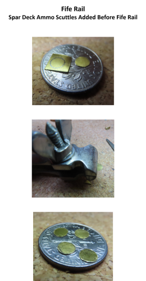
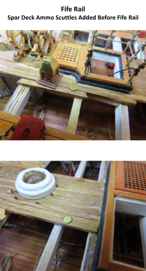
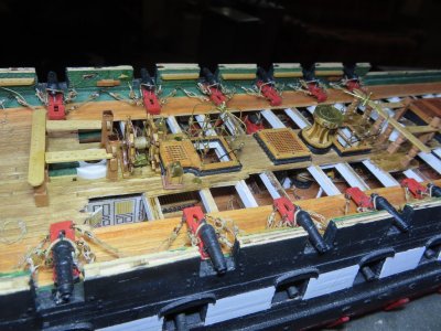
There's that dime again! 
Nice work! Keep up the steady progress.
Nice work! Keep up the steady progress.
Last edited:


Whew, she is a beast Jon. I enjoy all the details included and the busy deck, as well as your look through and cut aways. Cheers GrantFinally, the fife rails were glued into place.
Jon
View attachment 627008
View attachment 627009
View attachment 627010
View attachment 627011

Gun Port Lids
At this point, I thought it was time to start completing the hull by installing the rigging channels. But good old Murphy’s Law was enforced again. I realized I had to do something else first… the gun port lids, since they are just under the future channels.
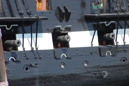
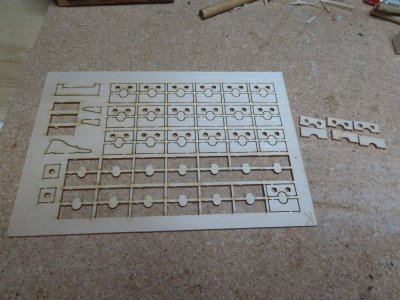
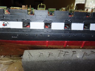
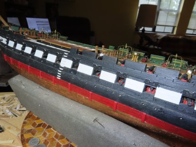
These were simple laser cut pieces supplied by the MS kit. And because they were to be installed in the open position, there was no need to rig them with pull lines or hinges because those would all be hidden. However, the one thing I wanted to simulate was the white weather strip where the two halves of the lids met. The weather strips go across the full width of the top lid and just in the half round cutout in the bottom lid. To actually create the stripping was too delicate so I created the illusion of them by painting the full bottom edge of the top lid and the half-round cutout white.
Jon
At this point, I thought it was time to start completing the hull by installing the rigging channels. But good old Murphy’s Law was enforced again. I realized I had to do something else first… the gun port lids, since they are just under the future channels.
These were simple laser cut pieces supplied by the MS kit. And because they were to be installed in the open position, there was no need to rig them with pull lines or hinges because those would all be hidden. However, the one thing I wanted to simulate was the white weather strip where the two halves of the lids met. The weather strips go across the full width of the top lid and just in the half round cutout in the bottom lid. To actually create the stripping was too delicate so I created the illusion of them by painting the full bottom edge of the top lid and the half-round cutout white.
Jon


These gunport lids look great, Jon. Excellent work! 
Not sure if I have asked this question on someone else's build log, so I apologize if it's a repeat, and you alluded to it a bit above with your comment about pull lines... how were these lids opened (and held opened), especially "back in the day"? I recall a picture somewhere (you probably have several of what I am referring to, Jon) that showed ropes going from the top lid into a hole that was in the bulwarks just above the gunport. The blue lines I made in one of your pics depicts what I was recalling seeing. Crew would pull those to open and... was there a cleat inside to tie to in order to keep them open?
Appreciate any insight and apologize for taking up space on your build log, Jon. Continued great work, sir!
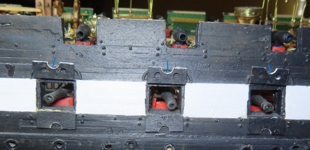
Not sure if I have asked this question on someone else's build log, so I apologize if it's a repeat, and you alluded to it a bit above with your comment about pull lines... how were these lids opened (and held opened), especially "back in the day"? I recall a picture somewhere (you probably have several of what I am referring to, Jon) that showed ropes going from the top lid into a hole that was in the bulwarks just above the gunport. The blue lines I made in one of your pics depicts what I was recalling seeing. Crew would pull those to open and... was there a cleat inside to tie to in order to keep them open?
Appreciate any insight and apologize for taking up space on your build log, Jon. Continued great work, sir!

These gunport lids look great, Jon. Excellent work!
Not sure if I have asked this question on someone else's build log, so I apologize if it's a repeat, and you alluded to it a bit above with your comment about pull lines... how were these lids opened (and held opened), especially "back in the day"? I recall a picture somewhere (you probably have several of what I am referring to, Jon) that showed ropes going from the top lid into a hole that was in the bulwarks just above the gunport. The blue lines I made in one of your pics depicts what I was recalling seeing. Crew would pull those to open and... was there a cleat inside to tie to in order to keep them open?
Appreciate any insight and apologize for taking up space on your build log, Jon. Continued great work, sir!
Yep! This is what I recall seeing previously! Thanks, Paul!
Hey Gregg,
I know you were going for an "1812-ish" representation. Just thought I'd point out that the hinged port lids came about a little later. Can't remember the exact timeline, but in 1812, they were removable and were stowed inside when the guns were in use.
I know you were going for an "1812-ish" representation. Just thought I'd point out that the hinged port lids came about a little later. Can't remember the exact timeline, but in 1812, they were removable and were stowed inside when the guns were in use.
Hey Gregg,
I know you were going for an "1812-ish" representation. Just thought I'd point out that the hinged port lids came about a little later. Can't remember the exact timeline, but in 1812, they were removable and were stowed inside when the guns were in use.
I do recall see that mentioned, Frank! Thanks for the reminder! I trust that I would have reminded myself of that fact before I got to that point down the road, but I always appreciate these subtle "oh-by-the-way" mentions. I need everyone looking out for me! Ha!
And after Paul's reminder of the USS Constitution Museum plans, I examined the plans and the exact location of the pull lines and then re-read Jon's post, where he accurately states the lines would be hidden. OK, sorry for muddling up your log, Jon!...there was no need to rig them with pull lines or hinges because those would all be hidden.