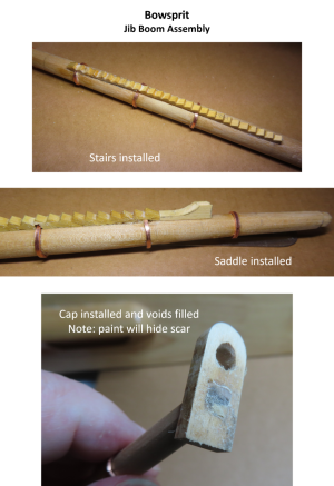
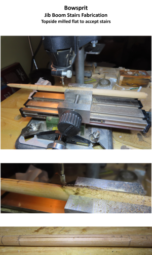
The surface of the jib boom is obviously a circle in the cross section, so my choice was to either create a concave surface on the back of the stairs or a flat strip on the jib boom to seat the steps. I decided to create a flat surface on the back of the stairs and on the jib boom. Because the jib’s top surface was not tapered, it was placed in the drill stand vise (which can accommodate the circular shape) so that I could shave off a ¼” wide flat length to accommodate the stairs with the ¼” router bit. The dry fit seems to work.
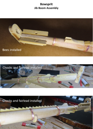
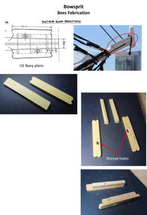
At the tip of the boom are the two bees. According to the practicum, each one is 3/16” x 1 1/16” x 1/16” thick. However, those dimensions are based on the plan view which foreshortens the width. The correct true width dimension is a bit wider based on the cross-section view, is ¼”, but only the nerd in me would notice that. That insight comes from taking mechanical drawing, learning the skills of a draftsman who worked with pencil, pen and paper in high school. Them were the “olden days.” Now, we are learning CAD skills. In practice, the difference in dimensions is infinitesimal on the model.
The sheeves on the bees are offset from each other. Normally, one would drill two holes and cut a groove between them to simulate the pulley wheel inside. Because the pully wheels are in the blocks of wood under the top slabs, trying to match the photos, I elongated the top openings and drilled just one hole through the under-block. The other would-be holes are covered by the top slabs so only half of the pulley wheels are seen.
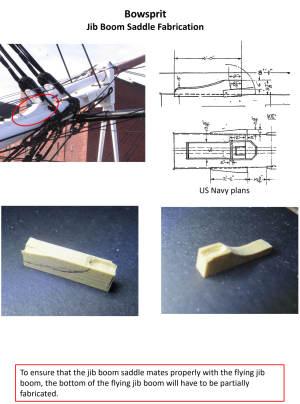
The jib boom saddle was quicky cut. It has a box cut into the end that is the seat. The US Navy plan looks a bit complicated, but that is because there is a rigid five-sided strap shown folded down. It will be added once the flying jib boom is installed. But now that I had the saddle, I needed to ensure that the flying jib boom would fit properly. It requires a “T” shaped tenon. The tenon sits in the box opening and the arms of the “T” rest on the top of the box.
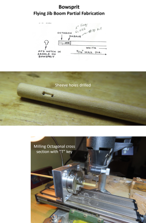
First the end of an 11/64” dowel was formed into an octagon shape using the Proxxon Dividing Attachment bolted onto the Proxxon X-Y table vertically so that the dowel was horizontal to the cutting blade in the Dremel tool. It took two attempts, but I got something that would work. Then I cut the sides to create the “T.” As I have mentioned before, the hard part for me is that I don’t have vertical fine-tuning controls on the Dremel drill stand. The good news is that it fit on the first try. It’s not as pretty as Mustfa’s, but it will work.
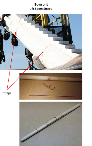
The practicum used 0.015” x 0.040” Styrene strips to create the four jib boom straps. Other builders used brass strips. I had 0.005” and 0.010” brass plate on hand which I thought were too thin. However, I did have 0.025” copper plate. Since the jib boom was to be completely painted hiding the strip material’s identity, I cut 3/64” copper strips using my Byrnes saw. These were wrapped around the boom at the appropriate locations.
At the tip of the boom are the two bees. According to the practicum, each one is 3/16” x 1 1/16” x 1/16” thick. However, those dimensions are based on the plan view which foreshortens the width. The correct true width dimension is a bit wider based on the cross-section view, is ¼”, but only the nerd in me would notice that. That insight comes from taking mechanical drawing, learning the skills of a draftsman who worked with pencil, pen and paper in high school. Them were the “olden days.” Now, we are learning CAD skills. In practice, the difference in dimensions is infinitesimal on the model.
The sheeves on the bees are offset from each other. Normally, one would drill two holes and cut a groove between them to simulate the pulley wheel inside. Because the pully wheels are in the blocks of wood under the top slabs, trying to match the photos, I elongated the top openings and drilled just one hole through the under-block. The other would-be holes are covered by the top slabs so only half of the pulley wheels are seen.
The jib boom saddle was quicky cut. It has a box cut into the end that is the seat. The US Navy plan looks a bit complicated, but that is because there is a rigid five-sided strap shown folded down. It will be added once the flying jib boom is installed. But now that I had the saddle, I needed to ensure that the flying jib boom would fit properly. It requires a “T” shaped tenon. The tenon sits in the box opening and the arms of the “T” rest on the top of the box.
First the end of an 11/64” dowel was formed into an octagon shape using the Proxxon Dividing Attachment bolted onto the Proxxon X-Y table vertically so that the dowel was horizontal to the cutting blade in the Dremel tool. It took two attempts, but I got something that would work. Then I cut the sides to create the “T.” As I have mentioned before, the hard part for me is that I don’t have vertical fine-tuning controls on the Dremel drill stand. The good news is that it fit on the first try. It’s not as pretty as Mustfa’s, but it will work.
The practicum used 0.015” x 0.040” Styrene strips to create the four jib boom straps. Other builders used brass strips. I had 0.005” and 0.010” brass plate on hand which I thought were too thin. However, I did have 0.025” copper plate. Since the jib boom was to be completely painted hiding the strip material’s identity, I cut 3/64” copper strips using my Byrnes saw. These were wrapped around the boom at the appropriate locations.